EP0620165B1 - Schlauchbeutel aus Verbundfolie - Google Patents
Schlauchbeutel aus Verbundfolie Download PDFInfo
- Publication number
- EP0620165B1 EP0620165B1 EP94810189A EP94810189A EP0620165B1 EP 0620165 B1 EP0620165 B1 EP 0620165B1 EP 94810189 A EP94810189 A EP 94810189A EP 94810189 A EP94810189 A EP 94810189A EP 0620165 B1 EP0620165 B1 EP 0620165B1
- Authority
- EP
- European Patent Office
- Prior art keywords
- tubular bag
- area
- film
- weakened area
- composite
- Prior art date
- Legal status (The legal status is an assumption and is not a legal conclusion. Google has not performed a legal analysis and makes no representation as to the accuracy of the status listed.)
- Expired - Lifetime
Links
- 229910052751 metal Inorganic materials 0.000 claims abstract description 23
- 239000002184 metal Substances 0.000 claims abstract description 23
- 239000011888 foil Substances 0.000 claims abstract description 22
- 239000002131 composite material Substances 0.000 claims description 20
- 239000004033 plastic Substances 0.000 claims description 11
- 229920003023 plastic Polymers 0.000 claims description 11
- 239000002985 plastic film Substances 0.000 abstract description 19
- 229920006255 plastic film Polymers 0.000 abstract description 19
- 230000003313 weakening effect Effects 0.000 description 7
- 238000004806 packaging method and process Methods 0.000 description 6
- 239000000126 substance Substances 0.000 description 5
- 239000000463 material Substances 0.000 description 3
- 230000000694 effects Effects 0.000 description 2
- 230000017525 heat dissipation Effects 0.000 description 2
- 238000000034 method Methods 0.000 description 2
- 239000000203 mixture Substances 0.000 description 2
- 238000003825 pressing Methods 0.000 description 2
- 238000003860 storage Methods 0.000 description 2
- 239000004698 Polyethylene Substances 0.000 description 1
- 229910052782 aluminium Inorganic materials 0.000 description 1
- XAGFODPZIPBFFR-UHFFFAOYSA-N aluminium Chemical compound [Al] XAGFODPZIPBFFR-UHFFFAOYSA-N 0.000 description 1
- 235000013361 beverage Nutrition 0.000 description 1
- 238000005520 cutting process Methods 0.000 description 1
- 238000001125 extrusion Methods 0.000 description 1
- 230000001771 impaired effect Effects 0.000 description 1
- 230000003993 interaction Effects 0.000 description 1
- 238000004519 manufacturing process Methods 0.000 description 1
- 238000002844 melting Methods 0.000 description 1
- 230000008018 melting Effects 0.000 description 1
- 239000004570 mortar (masonry) Substances 0.000 description 1
- 230000000149 penetrating effect Effects 0.000 description 1
- -1 polyethylene Polymers 0.000 description 1
- 229920000573 polyethylene Polymers 0.000 description 1
- 230000009993 protective function Effects 0.000 description 1
- 230000000717 retained effect Effects 0.000 description 1
- 238000003466 welding Methods 0.000 description 1
Images
Classifications
-
- B—PERFORMING OPERATIONS; TRANSPORTING
- B32—LAYERED PRODUCTS
- B32B—LAYERED PRODUCTS, i.e. PRODUCTS BUILT-UP OF STRATA OF FLAT OR NON-FLAT, e.g. CELLULAR OR HONEYCOMB, FORM
- B32B15/00—Layered products comprising a layer of metal
- B32B15/04—Layered products comprising a layer of metal comprising metal as the main or only constituent of a layer, which is next to another layer of the same or of a different material
- B32B15/08—Layered products comprising a layer of metal comprising metal as the main or only constituent of a layer, which is next to another layer of the same or of a different material of synthetic resin
-
- B—PERFORMING OPERATIONS; TRANSPORTING
- B29—WORKING OF PLASTICS; WORKING OF SUBSTANCES IN A PLASTIC STATE IN GENERAL
- B29C—SHAPING OR JOINING OF PLASTICS; SHAPING OF MATERIAL IN A PLASTIC STATE, NOT OTHERWISE PROVIDED FOR; AFTER-TREATMENT OF THE SHAPED PRODUCTS, e.g. REPAIRING
- B29C59/00—Surface shaping of articles, e.g. embossing; Apparatus therefor
- B29C59/007—Forming single grooves or ribs, e.g. tear lines, weak spots
-
- B—PERFORMING OPERATIONS; TRANSPORTING
- B32—LAYERED PRODUCTS
- B32B—LAYERED PRODUCTS, i.e. PRODUCTS BUILT-UP OF STRATA OF FLAT OR NON-FLAT, e.g. CELLULAR OR HONEYCOMB, FORM
- B32B1/00—Layered products having a non-planar shape
-
- B—PERFORMING OPERATIONS; TRANSPORTING
- B65—CONVEYING; PACKING; STORING; HANDLING THIN OR FILAMENTARY MATERIAL
- B65D—CONTAINERS FOR STORAGE OR TRANSPORT OF ARTICLES OR MATERIALS, e.g. BAGS, BARRELS, BOTTLES, BOXES, CANS, CARTONS, CRATES, DRUMS, JARS, TANKS, HOPPERS, FORWARDING CONTAINERS; ACCESSORIES, CLOSURES, OR FITTINGS THEREFOR; PACKAGING ELEMENTS; PACKAGES
- B65D75/00—Packages comprising articles or materials partially or wholly enclosed in strips, sheets, blanks, tubes or webs of flexible sheet material, e.g. in folded wrappers
- B65D75/52—Details
- B65D75/58—Opening or contents-removing devices added or incorporated during package manufacture
-
- B—PERFORMING OPERATIONS; TRANSPORTING
- B65—CONVEYING; PACKING; STORING; HANDLING THIN OR FILAMENTARY MATERIAL
- B65D—CONTAINERS FOR STORAGE OR TRANSPORT OF ARTICLES OR MATERIALS, e.g. BAGS, BARRELS, BOTTLES, BOXES, CANS, CARTONS, CRATES, DRUMS, JARS, TANKS, HOPPERS, FORWARDING CONTAINERS; ACCESSORIES, CLOSURES, OR FITTINGS THEREFOR; PACKAGING ELEMENTS; PACKAGES
- B65D77/00—Packages formed by enclosing articles or materials in preformed containers, e.g. boxes, cartons, sacks or bags
- B65D77/10—Container closures formed after filling
- B65D77/16—Container closures formed after filling by collapsing and twisting mouth portion
- B65D77/18—Container closures formed after filling by collapsing and twisting mouth portion and securing by a deformable clip or binder
-
- B—PERFORMING OPERATIONS; TRANSPORTING
- B32—LAYERED PRODUCTS
- B32B—LAYERED PRODUCTS, i.e. PRODUCTS BUILT-UP OF STRATA OF FLAT OR NON-FLAT, e.g. CELLULAR OR HONEYCOMB, FORM
- B32B2439/00—Containers; Receptacles
- B32B2439/40—Closed containers
- B32B2439/46—Bags
Definitions
- the invention relates to a tubular bag made of composite film with a metal film and at least one outer plastic film.
- Tubular bags of the type in question are mainly used for the storage of curable, in particular multicomponent, compositions such as mortar compositions and the like.
- the tubular bags are closed, for example by welding or by closing their ends by means of a closure clip, for example made of metal.
- the tubular bags for processing the masses are fed to squeezing devices, the tubular bags being emptied by pressing together on the device-side parts. In order to enable such an emptying, the tubular bag must be opened.
- the aforementioned preferred opening method of the tubular bag is associated with certain difficulties and does not always lead to the desired result.
- composite films are used as the material for the tubular bag, which have a relatively high mechanical Have strength.
- the composite foils consist of one or more plastic foils as well as one or possibly several metal foils.
- the composite films are always designed in such a way that a plastic film is provided at least on the outside.
- Materials for the composite films are preferably used as plastic, polyethylene and as metal, aluminum.
- the high mechanical strength of the composite films used which is required for storage and transport reasons, therefore has a disadvantageous effect on the opening process of the tubular bags.
- the intended opening aids on the device side are often not sufficient to overcome the mechanical strength of the composite films and thus to open the tubular bags at the right time at the desired time.
- EP-A-0 363 693 describes a packaging for coffee which is made from a composite film.
- the composite foil consists of plastic foils that envelop a metal foil.
- the packaging has a tear line extending essentially over the entire width of the packaging, along which the packaging can be torn open by hand.
- the tear line is formed either by a slot penetrating the entire film composite or by notches in both plastic films adjacent to the metal film.
- the plastic foils enclosing the metal foils are reduced in their wall thickness to such an extent that the mechanical stability and the resistance to chemical attack of the outer plastic foil are impaired.
- a beverage packaging is known from US-A-4,762,514, which forms the closest prior art, and is made from a film composite comprising plastic films and a metal film.
- the packaging has a narrow, pierceable opening area on its front side.
- the opening area is formed by cuts which are arranged radially or parallel to one another.
- the incisions made with a laser range from the outermost plastic layer to the metal layer of the composite film. As a result, the outermost plastic layer is damaged and even removed in the area of the incisions as far as the underlying metal layer.
- the exposed metal layer can be attacked by chemicals.
- the invention has for its object to provide a tubular bag, which ensures reliable opening in cooperation with device-side opening aids.
- the protective function of the outer plastic film, in particular against chemical influences, is to be retained.
- the object is achieved by that the pierceable opening area is a weakening area which acts as a predetermined breaking point in the outer plastic film and is produced by thermal action, the outer plastic film remaining intact in the weakening area and its wall thickness being essentially unchanged.
- the weakened area produced by thermal action thus weakens the mechanical strength of the tubular bag at a certain point. This position is selected so that it connects to the opening aids on the device side. As a result, in addition to maintaining the mechanical strength of the tubular bag, reliable opening at the desired point in time and at the intended location in conjunction with opening aids on the device side is ensured.
- the weakened area is created by thermal action. This can be done in a simple manner by applying heat to the outer plastic film which is above the melting point of this plastic film. As a result, material embrittlement reduces the mechanical strength of the outer plastic film in this area.
- the degree of thermal action for example duration and temperature, can be adjusted.
- the thermal effect is terminated on the metal foil by appropriate heat dissipation.
- the weakening area can only extend from the outside to the metal foil, but never also includes the metal foil or other plastic foils located after the metal foil.
- the weakened area can be punctiform, linear or annular. A certain area can also be understood in a punctiform manner.
- the thermal action can take place, for example, inductively or directly by means of electrodes, wherein the electrodes used can be adapted to the shape of the weakened area.
- the closure clip which serves to close the tubular bag if it is made of metal.
- the closure clip can be heated inductively, so that the weakening area is thus preferably arranged in the region of the closure clip.
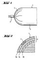
- the tubular bag 1 shows an end region of a tubular bag 1, which is closed with a closure clip 2.
- the tubular bag 1 consists of a composite film 3, which has a weakened area 4. This weakening area 4 is arranged on the end face of the tubular bag 1, so that it can interact with an optional piercing mandrel on the device as an opening aid.
- Fig. 2 shows a section through the composite film 3 of the tubular bag 1 in an enlarged view.
- the weakening region 4, which was produced by thermal action, can be clearly seen from this illustration.
- the composite film 3 consists of several films, namely in this example an outer plastic film 3a, an inner plastic film 3b and an intermediate metal film 3c.
- FIG. 2 also shows how the weakened area 4 only comprises the outer plastic film 3a, but has come to an end due to appropriate heat dissipation during production on the metal film 3c. This means that neither the metal foil 3c nor the plastic film 3b on the inside has been weakened by thermal action.
- the thickness in the weakened area 4 which is decisive for the mechanical strength of the composite film 3, has been reduced by the thickness of the outer plastic film 3a.
- the opening of the tubular bag 1 by device-side opening aids is thus facilitated at this point.
Landscapes
- Engineering & Computer Science (AREA)
- Mechanical Engineering (AREA)
- Bag Frames (AREA)
- Packages (AREA)
- Laminated Bodies (AREA)
- Making Paper Articles (AREA)
- Tubes (AREA)
Description
- Die Erfindung betrifft einen Schlauchbeutel aus Verbundfolie mit einer Metallfolie und zumindest einer aussenliegenden Kunststoffolie.
- Schlauchbeutel der hier in Rede stehenden Art werden vorwiegend zur Lagerung von aushärtbaren, insbesondere Mehrkomponentenmassen, wie beispielsweise Mörtelmassen und dergleichen , verwendet. Nach dem Verfüllen mit einer Komponente der Massen werden die Schlauchbeutel verschlossen, beispielsweise durch Verschweissen oder durch Verschliessen ihrer Enden mittels eines Verschlussclips, beispielsweise aus Metall. In diesem gefüllten Zustand werden die Schlauchbeutel zur Verarbeitung der Massen Auspressgeräten zugeführt, wobei unter Einwirkung geräteseitiger Teile die Schlauchbeutel durch Zusammenpressen entleert werden. Um eine solche Entleerung zu ermöglichen, ist eine Öffnung der Schlauchbeutel erforderlich.
- Zur Öffnung der Schlauchbeutel im vorgenannten Sinne sind verschiedene Möglichkeiten bekannt. So ist es beispielsweise zum einen bekannt, die Schlauchbeutel vor dem Einführen in die Auspressgeräte mittels spezieller Schneidvorrichtungen aufzuschneiden. Diese Art der Öffnung hat den Nachteil, dass unmittelbar nach dem Aufschneiden Masse aus dem Schlauchbeutel austreten kann und es so zu einer Verschmutzung sowohl der Auspressgeräte als auch deren Umgebung kommen kann. Aus diesem Grunde ist es zum anderen weit verbreitet, die Auspressgeräte mit einer Öffnungshilfe in Form eines Aufstechdorns oder einer Aufstechkante zu versehen. Das Zusammenwirken einer solchen Öffnungshilfe mit den in das Auspressgerät eingeführten Schlauchbeuteln soll zur Folge haben, dass der Schlauchbeutel an dieser Stelle geöffnet wird, was bei geeigneter Auslegung des Auspressgerätes beispielsweise erst nach dessen Schliessen erfolgen soll.
- In der Praxis hat sich nun aber gezeigt, dass die vorgenannte bevorzugte Öffnungsmethode der Schlauchbeutel mit gewissen Schwierigkeiten verbunden ist und nicht immer zufriedenstellend zum Ziel führt. Dies rührt daher, dass als Material für die Schlauchbeutel Verbundfolien verwendet werden, die eine relativ hohe mechanische Festigkeit aufweisen. Beispielsweise bestehen die Verbundfolien aus einer oder mehreren Kunststoffolien sowie einer oder gegebenenfalls auch mehreren Metallfolien. Zum Schutze insbesondere chemischer Einwirkungen sind die Verbundfolien aber immer so ausgelegt, dass zumindest aussen eine Kunststoffolie vorgesehen ist.
- An Materialien für die Verbundfolien finden in bevorzugter Weise als Kunststoff Polyäthylen und als Metall Aluminium Anwendung.
- Die aus lagerungs- und transporttechnischen Gründen erforderliche hohe mechanische Festigkeit der verwendeten Verbundfolien wirkt sich somit nachteilig auf den Öffnungsvorgang der Schlauchbeutel aus. So reichen die vorgesehenen geräteseitigen Öffnungshilfen oftmals nicht aus, die mechanische Festigkeit der Verbundfolien zu überwinden und so die Schlauchbeutel zum gewünschten Zeitpunkt an der richtigen Stelle zu öffnen.
- In der EP-A-0 363 693 ist eine Verpackung für Kaffee beschrieben, die aus einer Verbundfolie gefertigt ist. Die Verbundfolie besteht aus Kunststoffolien, die eine Metallfolie umhüllen. Die Verpackung weist eine sich im wesentlichen über die gesamte Breite der Verpackung erstreckenden Aufreisslinie auf, entlang der die Verpackung von Hand aufreissbar ist. Die Aufreisslinie ist entweder durch einen den gesamten Folienverbund penetrierenden Schlitz oder durch Kerben in beiden an die Metallfolie angrenzenden Kunststoffolien gebildet. Im Fall des durch den Folienverbund reichenden Schlitzes wird die äussere Kunststoffolie verletzt und ist die Metallfolie einem Chemikalienangriff ausgesetzt. Bei den Kerben werden die die Metallfolien einschliessenden Kunststoffolien soweit in ihrer Wandstärke reduziert, dass die mechanische Stabilität und die Widerstandsfähigkeit gegen Chemikalienangriff der äusseren Kunststoffolie beeinträchtigt ist.
- Aus der den nächsten Stand der Technik bildenden US-A-4,762,514 ist eine Getränkeverpackung bekannt, die aus einem Kunststoffolien und eine Metallfolie umfassenden Folienverbund gefertigt ist. In ihrer Stirnseite besitzt die Verpackung einen eng begrenzten, aufstechbaren Öffnungsbereich. Der Öffnungsbereich ist durch Einschnitte gebildet, die radial oder parallel zueinander angeordnet sind. Die mit einem Laser hergestellten Einschnitte reichen von der äussersten Kunststoffschicht bis zur Metallschicht der Verbundfolie. Dadurch wird die äusserste Kunststoffschicht verletzt und im Bereich der Einschnitte sogar bis zur darunter liegenden Metallschicht abgetragen. Dadurch kann die freigelegte Metallschicht von Chemikalien angegriffen werden.
- Der Erfindung liegt die Aufgabe zugrunde, einen Schlauchbeutel zu schaffen, welcher ein zuverlässiges Öffnen im Zusammenwirken mit geräteseitigen Öffnungshilfen sicherstellt. Dabei soll die Schutzfunktion der äusseren Kunststoffolie insbesondere gegen chemische Einwirkungen erhalten bleiben.
- Erfindungsgemäss wird die Aufgabe dadurch gelöst, dass der aufstechbare Öffnungsbereich ein in der aussen liegenden Kunststoffolie als Sollbruchstelle wirkender Schwächungsbereich ist, der durch thermische Einwirkung hergestellt ist, wobei die aussen liegende Kunststoffolie im Schwächungsbereich unverletzt bleibt und ihre Wandstärke im wesentlichen unverändert ist.
- Der durch thermische Einwirkung hergestellte Schwächungsbereich schwächt somit an einer bestimmten Stelle die mechanische Festigkeit des Schlauchbeutels. Diese Stelle wird so gewählt, dass sie mit den geräteseitigen Öffnungshilfen in Verbindung tritt. Dadurch ist nebst der Beibehaltung der mechanischen Festigkeit des Schlauchbeutels insgesamt ein zuverlässiges Öffnen zum gewünschten Zeitpunkt und an der vorgesehenen Stelle in Verbindung mit geräteseitigen Öffnungshilfen gewährleistet.
- Der Schwächungsbereich wird durch thermische Einwirkung hergestellt. Dies kann in einfacher Weise dadurch geschehen, dass auf die aussenliegende Kunststoffolie Wärme aufgebracht wird, die über dem Schmelzpunkt dieser Kunststoffolie liegt. Dadurch tritt in diesem Bereich eine die mechanische Festigkeit der aussenliegenden Kunststoffolie herabsetzende Materialversprödung ein.
- Je nach Dicke und Beschaffenheit der aussenliegenden Kunststoffolie kann der Grad der thermischen Einwirkung, beispielsweise Zeitdauer und Temperatur, angepasst werden.
- Aufgrund der in der Verbundfolie vorhandenen Metallfolie findet die thermische Einwirkung aber durch entsprechende Wärmeableitung ihren Abschluss an der Metallfolie. Dies bedeutet, dass der Schwächungsbereich lediglich von aussen bis zur Metallfolie reichen kann, aber niemals auch die Metallfolie oder weitere, nach der Metallfolie innenliegende, Kunststoffolien umfasst.
- Je nach Ausgestaltung der Anwendung findenden geräteseitigen Öffnungshilfen kann der Schwächungsbereich punktförmig, linienförmig oder ringförmig ausgebildet sein. Dabei kann punktförmig auch ein gewisser Flächenbereich verstanden werden.
- Die thermische Einwirkung kann beispielsweise induktiv oder direkt mittels Elektroden erfolgen, wobei die verwendeten Elektroden der Form des Schwächungsbereiches angepasst sein können.
- Anstelle der Verwendung einer separaten Elektrode besteht eine einfache Möglichkeit darin, den dem Verschluss des Schlauchbeutels dienenden Verschlussclip zu verwenden, wenn dieser aus Metall besteht. In einem solchen Falle kann der Verschlussclip induktiv erwärmt werden, so dass damit in bevorzugter Weise der Schwächungsbereich im Bereich des Verschlussclips angeordnet ist.
- Die Erfindung wird nachstehend anhand von Zeichnungen, welche ein Ausführungsbeispiel wiedergeben, näher erläutert. Es zeigen:
- Fig. 1
- einen Endbereich eines Schlauchbeutels mit erfindungsgemässem Schwächungsbereich;
- Fig. 2
- einen vergrösserten Schnitt durch die Verbundfolie des Folienbeutels der Fig. 1 mit Schwächungsbereich.
- Die Fig. 1 zeigt einen Endbereich eines Schlauchbeutels 1, der mit einem Verschlussclip 2 verschlossen ist. Der Schlauchbeutel 1 besteht aus einer Verbundfolie 3, welche einen Schwächungsbereich 4 aufweist. Dieser Schwächungsbereich 4 ist stirnseitig am Schlauchbeutel 1 angeordnet, so dass er mit einem gegebenenfalls vorhandenen, geräteseitigen Aufstechdorn als Öffnungshilfe zusammenwirken kann.
- Die Fig. 2 zeigt einen Schnitt durch die Verbundfolie 3 des Schlauchbeutels 1 in vergrösserter Darstellung. Aus dieser Darstellung ist deutlich der Schwächungsbereich 4 zu sehen, welcher durch thermische Einwirkung hergestellt wurde.
- Wie die Fig. 2 deutlich zeigt, besteht die Verbundfolie 3 aus mehreren Folien, nämlich in diesem Beispiel aus einer aussenliegenden Kunststoffolie 3a, einer innenliegenden Kunststoffolie 3b und einer dazwischenliegenden Metallfolie 3c. Die Fig. 2 zeigt ferner, wie der Schwächungsbereich 4 lediglich die aussenliegende Kunststoffolie 3a umfasst, jedoch durch entsprechende Wärmeableitung bei der Herstellung an der Metallfolie 3c ein Ende gefunden hat. Damit ist weder die Metallfolie 3c noch die innenliegende Kunststoffolie 3b durch thermische Einwirkung geschwächt worden. Insgesamt ist die für die mechanische Festigkeit der Verbundfolie 3 massgebende Stärke im Schwächungsbereich 4 um die Stärke der aussenliegenden Kunststoffolie 3a verringert worden. Die Öffnung des Schlauchbeutels 1 durch geräteseitige Öffnungshilfen wird damit an dieser Stelle erleichtert.
Claims (5)
- Schlauchbeutel aus Verbundfolie (3) mit einer Metallfolie (3c) und zumindest einer aussenliegenden Kunststoffolie (3a), der stirnseitig einen eng begrenzten, aufstechbaren Öffnungsbereich (4) aufweist, dadurch gekennzeichnet, dass der aufstechbare Öffnungsbereich (4) ein in der aussen liegenden Kunststoffolie (3a) als Sollbruchstelle wirkender Schwächungsbereich ist, der durch thermische Einwirkung hergestellt ist, wobei die aussen liegende Kunststoffolie (3a) im Schwächungsbereich unverletzt bleibt und ihre Wandstärke im wesentlichen unverändert ist.
- Schlauchbeutel nach Anspruch 1, dadurch gekennzeichnet, dass der Schwächungsbereich (4) punktförmig ausgestaltet ist.
- Schlauchbeutel nach Anspruch 1, dadurch gekennzeichnet, dass der Schwächungsbereich linienförmig ausgestaltet ist.
- Schlauchbeutel nach Anspruch 1, dadurch gekennzeichnet, dass der Schwächungsbereich ringförmig ausgestaltet ist.
- Schlauchbeutel nach einem der Ansprüche 1 bis 4, dadurch gekennzeichnet, dass der Schwächungsbereich im Bereich eines Verschlussclips (2) angeordnet ist.
Applications Claiming Priority (2)
| Application Number | Priority Date | Filing Date | Title |
|---|---|---|---|
| DE4312192 | 1993-04-14 | ||
| DE4312192A DE4312192A1 (de) | 1993-04-14 | 1993-04-14 | Schlauchbeutel aus Verbundfolie |
Publications (2)
| Publication Number | Publication Date |
|---|---|
| EP0620165A1 EP0620165A1 (de) | 1994-10-19 |
| EP0620165B1 true EP0620165B1 (de) | 1997-06-04 |
Family
ID=6485459
Family Applications (1)
| Application Number | Title | Priority Date | Filing Date |
|---|---|---|---|
| EP94810189A Expired - Lifetime EP0620165B1 (de) | 1993-04-14 | 1994-03-28 | Schlauchbeutel aus Verbundfolie |
Country Status (6)
| Country | Link |
|---|---|
| US (1) | US5480067A (de) |
| EP (1) | EP0620165B1 (de) |
| JP (1) | JPH06321258A (de) |
| AT (1) | ATE153960T1 (de) |
| DE (2) | DE4312192A1 (de) |
| ES (1) | ES2102176T3 (de) |
Cited By (2)
| Publication number | Priority date | Publication date | Assignee | Title |
|---|---|---|---|---|
| US6988496B1 (en) | 1999-02-23 | 2006-01-24 | Boehringer Ingelheim International Gmbh | Cartridge for a liquid |
| US7963955B2 (en) | 1998-02-27 | 2011-06-21 | Boehringer Ingelheim International Gmbh | Container for a medicinal liquid |
Families Citing this family (20)
| Publication number | Priority date | Publication date | Assignee | Title |
|---|---|---|---|---|
| DE29602111U1 (de) * | 1996-02-07 | 1997-06-05 | 3M ESPE AG, 82229 Seefeld | Schlauchbeutel für fließfähige Massen |
| DE19615422A1 (de) * | 1996-04-19 | 1997-11-20 | Boehringer Ingelheim Kg | Zweikammer-Kartusche für treibgasfreie Dosieraerosole |
| DE19703637C5 (de) * | 1997-01-31 | 2004-09-30 | Schwarz Druck Gmbh & Co Kg | Echtheitsprüfsystem |
| DE19733782C2 (de) * | 1997-08-05 | 2000-02-10 | Tils Peter | Verfahren zum Verpacken von zu entsorgendem Gut |
| US6685691B1 (en) | 1998-02-27 | 2004-02-03 | Boehringer Ingelheim Gmbh | Container for a medicinal liquid |
| DE19808295A1 (de) | 1998-02-27 | 1999-11-11 | Boehringer Ingelheim Int | Behälter für eine medizinische Flüssigkeit |
| EP0992438A1 (de) * | 1998-10-09 | 2000-04-12 | Wilhelm A. Keller | Dünnwandige Kartusche für wiederverwendbare Abgabevorrichtung |
| DE19851404A1 (de) | 1998-11-07 | 2000-05-11 | Boehringer Ingelheim Int | Druckausgleichsvorrichtung für einen Doppelbehälter |
| DE10009265A1 (de) * | 2000-02-26 | 2001-08-30 | Hilti Ag | Kappe für Schlauchbeutel |
| DE10019072A1 (de) * | 2000-04-18 | 2001-10-25 | Hilti Ag | Verpackung für Mörtelmassen |
| US8403176B2 (en) * | 2003-01-22 | 2013-03-26 | Allergan, Inc. | Controlled drop dispensing container |
| DE602004022075D1 (de) * | 2003-10-21 | 2009-08-27 | Novo Nordisk As | Reservoirvorrichtung mit integriertem befestigungsmittel |
| US7368170B2 (en) * | 2004-07-01 | 2008-05-06 | Illinois Tool Works Inc. | Viscous chemical anchoring adhesive |
| US7226650B2 (en) * | 2004-07-01 | 2007-06-05 | Illinois Tool Works Inc. | Wrapped highly viscous chemical anchoring adhesive |
| DE102008040738A1 (de) * | 2008-07-25 | 2010-01-28 | Hilti Aktiengesellschaft | Foliengebinde |
| US8814430B2 (en) | 2010-02-23 | 2014-08-26 | Kraft Foods R&D, Inc. | Food package having opening feature |
| US8544683B2 (en) | 2010-10-29 | 2013-10-01 | Nordson Corporation | Multiple component dispensing cartridge and method with side-by-side fluid chambers |
| US9579686B2 (en) | 2012-10-29 | 2017-02-28 | Nordson Corporation | Fluid dispensing assemblies and methods of dispensing fluids from containers |
| US9757763B2 (en) | 2013-10-31 | 2017-09-12 | Nordson Corporation | Side by side cartridge assemblies and related methods |
| US9821512B2 (en) * | 2014-04-10 | 2017-11-21 | Dow Global Technologies Llc | Method and apparatus for dispensing reactive two-part systems |
Family Cites Families (8)
| Publication number | Priority date | Publication date | Assignee | Title |
|---|---|---|---|---|
| US3477614A (en) * | 1968-01-25 | 1969-11-11 | Nat Dairy Prod Corp | Dispenser |
| US3661322A (en) * | 1970-04-06 | 1972-05-09 | Kraftco Corp | Package seal |
| DE7526045U (de) * | 1975-08-16 | 1975-12-11 | Hoechst Ag | Beutel mit Einstichstelle |
| US4762514A (en) * | 1985-11-01 | 1988-08-09 | Fujimori Kogyo Co., Ltd. | Method of making beverage packaging bag |
| DE3826887A1 (de) * | 1988-08-08 | 1990-02-15 | Niedecker Herbert | Schlauchfoermige verpackung aus flexiblem material fuer pastoese massen |
| DE3833939A1 (de) * | 1988-10-05 | 1990-04-12 | Jacobs Suchard Ag | Vakuum-verpackung, verbundfolie zur herstellung einer vakuum-verpackung sowie verfahren zur herstellung derselben |
| US5035348A (en) * | 1989-09-01 | 1991-07-30 | Institute Guilfoyle | Container having a pressure-rupturable seal for dispensing contents |
| US5310262A (en) * | 1992-06-02 | 1994-05-10 | Bemis Company, Inc. | Flexible package with an easy open arrangement |
-
1993
- 1993-04-14 DE DE4312192A patent/DE4312192A1/de not_active Withdrawn
-
1994
- 1994-03-28 ES ES94810189T patent/ES2102176T3/es not_active Expired - Lifetime
- 1994-03-28 EP EP94810189A patent/EP0620165B1/de not_active Expired - Lifetime
- 1994-03-28 AT AT94810189T patent/ATE153960T1/de not_active IP Right Cessation
- 1994-03-28 DE DE59402968T patent/DE59402968D1/de not_active Expired - Fee Related
- 1994-04-13 JP JP6074899A patent/JPH06321258A/ja active Pending
- 1994-04-14 US US08/227,416 patent/US5480067A/en not_active Expired - Fee Related
Cited By (3)
| Publication number | Priority date | Publication date | Assignee | Title |
|---|---|---|---|---|
| US7963955B2 (en) | 1998-02-27 | 2011-06-21 | Boehringer Ingelheim International Gmbh | Container for a medicinal liquid |
| US6988496B1 (en) | 1999-02-23 | 2006-01-24 | Boehringer Ingelheim International Gmbh | Cartridge for a liquid |
| US7802568B2 (en) | 1999-02-23 | 2010-09-28 | Boehringer Ingelheim International Gmbh | Cartridge for a liquid |
Also Published As
| Publication number | Publication date |
|---|---|
| JPH06321258A (ja) | 1994-11-22 |
| EP0620165A1 (de) | 1994-10-19 |
| DE4312192A1 (de) | 1994-10-20 |
| DE59402968D1 (de) | 1997-07-10 |
| ES2102176T3 (es) | 1997-07-16 |
| US5480067A (en) | 1996-01-02 |
| ATE153960T1 (de) | 1997-06-15 |
Similar Documents
| Publication | Publication Date | Title |
|---|---|---|
| EP0620165B1 (de) | Schlauchbeutel aus Verbundfolie | |
| DE69711704T2 (de) | Verfahren zum herstellen einer von einem laser vorgeschnittenen packung sowie packung | |
| EP0347522B1 (de) | Aus Folienschlauch hergestellter Verpackungsbeutel | |
| DE3526113C2 (de) | ||
| DE69928419T2 (de) | Behälter mit schrumpfetikett | |
| DE69013931T2 (de) | Vorrichtung zur entnahme von flüssigem füllmaterial durch eine flexible beutelwand. | |
| AT522907B1 (de) | Manschettenförmiges Außenteil sowie damit ausgestatteter Kombi-Verpackungsbehälter | |
| DE60219688T2 (de) | Verpackung, wie zum beispiel beutel, mit ausgerichteter aufreissöffnung | |
| DE3422547A1 (de) | Manipuliersichere verschlusskappe fuer behaelter | |
| EP0596836A1 (de) | Garantieverschluss und Verfahren und Vorrichtung zur Herstellung eines Garantieverschlusses | |
| WO2008092289A2 (de) | Verschliessvorrichtung aus kunststoff mit schneidhülse | |
| DE4335970A1 (de) | Folienbeutelpackung mit Folienbeutel und Bodenteil | |
| DE202011004614U1 (de) | Foliendeckel zum Verschließen eines Behälters | |
| EP3861545A1 (de) | SICHERHEITSETIKETT FÜR EIN MEHRTEILIGES GEFÄß, VERWENDEN EINES SICHERHEITSETIKETTS, SYSTEM UND VERFAHREN ZUM APPLIZIEREN EINES SICHERHEITSETIKETTS FÜR EIN MEHRTEILIGES GEFÄß | |
| DE69706718T2 (de) | Öffnungsvorrichtung für einen Verpackungsbehälter | |
| DE8803229U1 (de) | Verpackung für Gegenstände, insbesondere von Quaderform | |
| DE60211851T2 (de) | Verpackung für einen rohrförmigen stapel von runden keksen | |
| EP0316269B1 (de) | Verschluss für Behälter, insbesondere Flaschen | |
| DE2845107C2 (de) | Verfahren zum Einbringen einer Klebemasse in ein Bohrloch | |
| DE68909328T2 (de) | Vorrichtung zum Öffnen und Verschliessen eines Beutels aus Kunststoff mit einer Haltevorrichtung. | |
| EP0183064B1 (de) | Flachbeutel | |
| EP1853490B1 (de) | Verschlusskappe | |
| DE29905854U1 (de) | Beutelverpackung | |
| EP0676336A2 (de) | Verfahren zum Abdecken einer Schnittkante einer Öffnung eines Behälters mit einem Schutzbezug | |
| EP2284091B1 (de) | Seitenfaltenbeutel aus einer Kunststofffolie |
Legal Events
| Date | Code | Title | Description |
|---|---|---|---|
| PUAI | Public reference made under article 153(3) epc to a published international application that has entered the european phase |
Free format text: ORIGINAL CODE: 0009012 |
|
| AK | Designated contracting states |
Kind code of ref document: A1 Designated state(s): AT CH DE ES FR GB IT LI |
|
| 17P | Request for examination filed |
Effective date: 19941107 |
|
| 17Q | First examination report despatched |
Effective date: 19951219 |
|
| GRAG | Despatch of communication of intention to grant |
Free format text: ORIGINAL CODE: EPIDOS AGRA |
|
| GRAH | Despatch of communication of intention to grant a patent |
Free format text: ORIGINAL CODE: EPIDOS IGRA |
|
| GRAH | Despatch of communication of intention to grant a patent |
Free format text: ORIGINAL CODE: EPIDOS IGRA |
|
| GRAA | (expected) grant |
Free format text: ORIGINAL CODE: 0009210 |
|
| ITF | It: translation for a ep patent filed | ||
| AK | Designated contracting states |
Kind code of ref document: B1 Designated state(s): AT CH DE ES FR GB IT LI |
|
| REF | Corresponds to: |
Ref document number: 153960 Country of ref document: AT Date of ref document: 19970615 Kind code of ref document: T |
|
| REG | Reference to a national code |
Ref country code: CH Ref legal event code: EP |
|
| REF | Corresponds to: |
Ref document number: 59402968 Country of ref document: DE Date of ref document: 19970710 |
|
| GBT | Gb: translation of ep patent filed (gb section 77(6)(a)/1977) |
Effective date: 19970620 |
|
| REG | Reference to a national code |
Ref country code: ES Ref legal event code: FG2A Ref document number: 2102176 Country of ref document: ES Kind code of ref document: T3 |
|
| ET | Fr: translation filed | ||
| PGFP | Annual fee paid to national office [announced via postgrant information from national office to epo] |
Ref country code: CH Payment date: 19980304 Year of fee payment: 5 |
|
| PGFP | Annual fee paid to national office [announced via postgrant information from national office to epo] |
Ref country code: ES Payment date: 19980326 Year of fee payment: 5 |
|
| PG25 | Lapsed in a contracting state [announced via postgrant information from national office to epo] |
Ref country code: GB Free format text: LAPSE BECAUSE OF NON-PAYMENT OF DUE FEES Effective date: 19980328 Ref country code: AT Free format text: LAPSE BECAUSE OF NON-PAYMENT OF DUE FEES Effective date: 19980328 |
|
| PLBE | No opposition filed within time limit |
Free format text: ORIGINAL CODE: 0009261 |
|
| STAA | Information on the status of an ep patent application or granted ep patent |
Free format text: STATUS: NO OPPOSITION FILED WITHIN TIME LIMIT |
|
| 26N | No opposition filed | ||
| GBPC | Gb: european patent ceased through non-payment of renewal fee |
Effective date: 19980328 |
|
| PGFP | Annual fee paid to national office [announced via postgrant information from national office to epo] |
Ref country code: FR Payment date: 19990128 Year of fee payment: 6 |
|
| PG25 | Lapsed in a contracting state [announced via postgrant information from national office to epo] |
Ref country code: ES Free format text: LAPSE BECAUSE OF NON-PAYMENT OF DUE FEES Effective date: 19990329 |
|
| PG25 | Lapsed in a contracting state [announced via postgrant information from national office to epo] |
Ref country code: LI Free format text: LAPSE BECAUSE OF NON-PAYMENT OF DUE FEES Effective date: 19990331 Ref country code: CH Free format text: LAPSE BECAUSE OF NON-PAYMENT OF DUE FEES Effective date: 19990331 |
|
| REG | Reference to a national code |
Ref country code: CH Ref legal event code: PL |
|
| PGFP | Annual fee paid to national office [announced via postgrant information from national office to epo] |
Ref country code: DE Payment date: 19991231 Year of fee payment: 7 |
|
| PG25 | Lapsed in a contracting state [announced via postgrant information from national office to epo] |
Ref country code: FR Free format text: LAPSE BECAUSE OF NON-PAYMENT OF DUE FEES Effective date: 20001130 |
|
| REG | Reference to a national code |
Ref country code: FR Ref legal event code: ST |
|
| REG | Reference to a national code |
Ref country code: ES Ref legal event code: FD2A Effective date: 20010503 |
|
| PG25 | Lapsed in a contracting state [announced via postgrant information from national office to epo] |
Ref country code: DE Free format text: LAPSE BECAUSE OF NON-PAYMENT OF DUE FEES Effective date: 20020101 |
|
| PG25 | Lapsed in a contracting state [announced via postgrant information from national office to epo] |
Ref country code: IT Free format text: LAPSE BECAUSE OF NON-PAYMENT OF DUE FEES;WARNING: LAPSES OF ITALIAN PATENTS WITH EFFECTIVE DATE BEFORE 2007 MAY HAVE OCCURRED AT ANY TIME BEFORE 2007. THE CORRECT EFFECTIVE DATE MAY BE DIFFERENT FROM THE ONE RECORDED. Effective date: 20050328 |