EP0620180B1 - Pince de sécurité pour un équipement mobile sur rail, comme p.e. une grue - Google Patents
Pince de sécurité pour un équipement mobile sur rail, comme p.e. une grue Download PDFInfo
- Publication number
- EP0620180B1 EP0620180B1 EP94105306A EP94105306A EP0620180B1 EP 0620180 B1 EP0620180 B1 EP 0620180B1 EP 94105306 A EP94105306 A EP 94105306A EP 94105306 A EP94105306 A EP 94105306A EP 0620180 B1 EP0620180 B1 EP 0620180B1
- Authority
- EP
- European Patent Office
- Prior art keywords
- rail
- tongs
- safety tongs
- mentioned
- arms
- Prior art date
- Legal status (The legal status is an assumption and is not a legal conclusion. Google has not performed a legal analysis and makes no representation as to the accuracy of the status listed.)
- Expired - Lifetime
Links
- 238000005452 bending Methods 0.000 claims 1
- 238000009434 installation Methods 0.000 claims 1
- 230000006835 compression Effects 0.000 description 24
- 238000007906 compression Methods 0.000 description 24
- 239000000853 adhesive Substances 0.000 description 2
- 230000001070 adhesive effect Effects 0.000 description 2
- 238000006243 chemical reaction Methods 0.000 description 1
- 238000010276 construction Methods 0.000 description 1
- 238000006073 displacement reaction Methods 0.000 description 1
- 239000010720 hydraulic oil Substances 0.000 description 1
- 239000003921 oil Substances 0.000 description 1
- 230000000284 resting effect Effects 0.000 description 1
Images


Classifications
-
- B—PERFORMING OPERATIONS; TRANSPORTING
- B66—HOISTING; LIFTING; HAULING
- B66C—CRANES; LOAD-ENGAGING ELEMENTS OR DEVICES FOR CRANES, CAPSTANS, WINCHES, OR TACKLES
- B66C9/00—Travelling gear incorporated in or fitted to trolleys or cranes
- B66C9/18—Travelling gear incorporated in or fitted to trolleys or cranes with means for locking trolleys or cranes to runways or tracks to prevent inadvertent movements
Definitions
- the invention relates to safety tongs for a rail-bound system, e.g. a crane with tong arms which are movable around fixed articulation points attached to a support, the tong arms at one end possibly carrying press jaws via articulately adjustable intermediate members and which are actuated at the other end by an actuating device attached to a frame, at least on the inside a press jaw at least one wedge-shaped groove guide is provided, in which a wedge gripping the rail is guided, the wedge being able to be brought into the region of the greatest opening width of the groove guide (starting position).
- a rail-bound system e.g. a crane with tong arms which are movable around fixed articulation points attached to a support, the tong arms at one end possibly carrying press jaws via articulately adjustable intermediate members and which are actuated at the other end by an actuating device attached to a frame, at least on the inside a press jaw at least one wedge-shaped groove guide is provided, in which a wedge gripping the rail is guided, the wedge
- DE-A 2 441 122 discloses safety tongs for rail-bound vehicles, in which a press jaw which can be placed on the rail is provided.
- This press jaw has two mirror-image arranged, parallel to the longitudinal axis of the rail aligned support bearing with wedge surfaces, with these wedge surfaces friction members are arranged parallel to the longitudinal side of the rail.
- the rail tongs are to be released with the aid of a piston-cylinder drive that pulls the friction elements together against the force of the compression springs.
- a disadvantage of this embodiment is that when the rail tongs or the rail are heated, the frictional connection becomes ever stronger and can no longer be released by the piston-cylinder drive.
- the invention is therefore based on the object to develop a safety pliers of the type mentioned in such a way that the crane system is securely secured against displacement even in the case of wavy rails.
- a frame is provided for receiving the rail tongs, the tongs arms being slidably received by the frame.
- At least one press jaw is provided with mirror guides arranged in a wedge shape to the rail, in which wedge-engaging wedges are guided, which can be moved towards one another by spring force.
- the press jaws are articulated on tong arms, the tong arms being connected to one another by a piston-cylinder drive, and a compression spring being provided parallel to the piston-cylinder drive between the tong arms.
- a piston-cylinder drive in conjunction with a compression spring, it is achieved that the entire rail tongs can be manufactured more cheaply than in the case of rail tongs with a scissor-type frame, or an actuating device with an electrohydraulic drive for actuating the tong arms or the pressing jaws.
- the press jaws are advantageously connected by a ball-and-socket joint and thus movable on all sides with the respective clamp arm, so that the press jaws can always be brought into an optimal position relative to the rail.
- the groove guide is preferably bent towards the rail from approximately half its length in order to increase the pressing force of the trowel guided through the groove guide on the rail.
- this measure turns out to be advantageous, since in principle only one press jaw exerts force on the rail, since the other press jaw only the reaction force applies.
- the wedges are held in the starting position by a compression spring.
- the trowel In the starting position, the trowel is in the middle of the press jaw.
- the compression spring is guided through the respective wedge and is supported on the press jaw.
- the wedge has a corresponding recess for guiding the compression spring; the compression spring is supported by the groove guide.
- each press jaw is provided with a wedge guided in a groove.
- the trowel is diagonally opposite to each other.
- the respective wedge is located directly on the other press jaw.
- one press jaw is responsible for one direction in which the crane is moved.
- the trowel in place before the rail tongs are placed on the rail Be brought home.
- the advantage of this embodiment is that the forces occurring when braking the crane can be better absorbed by the rail tongs, since the wedges and the groove guides can be dimensioned larger with the same press jaw dimensions.
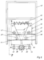
- the frame designated 42 is part of the rail-bound system, for. B. the crane.
- the rail clamp designated as a whole with 48 is held.
- the rail clamp 48 consists of the clamp arms 35, 36, each of which is present as a pair in the present case.
- the piston-cylinder drive 39 and the compression spring 40 are located between the tong arms 35, 36.
- a support 41 is provided between the tong arms 35, 36 and is connected to the tong arms 35, 36 by the articulation points 37, 38.
- the piston-cylinder drive 39 works in the direction of the force of the spring 40. Because the piston-cylinder drive 39 is provided with a check valve and because the spring 40 acts in such a way that the pressing jaws 28, 29 move in the direction of the rail ensures that the rail clamp cannot be released accidentally. For this would be a prerequisite that the check valve was loosened and the piston of the piston cylinder drive was acted upon from the opposite side with hydraulic oil.
- the rail tongs can therefore only be released if the piston-cylinder drive is switched over and therefore pulls the pressing jaws 28, 29 away from the rail 17 against the force of the spring 40.
- the frame 42 also has the crossbeams 46, on which the rail clamp designated as a whole with 48 is slidably mounted.
- the tong arms 35, 36 or tong arm pairs have rollers 47 on both sides which rest on the crossmember 46 (FIG. 6).
- the movable mounting of the rail arms 48 by the frame 42 serves the purpose of always bringing the press jaws 28, 29 in an optimal position to the clamp 17 in the case of strongly wavy rails 17.
- This purpose also serves the measure of connecting the tong arms 35 and 36 to the press jaws 28 and 29 by means of a ball joint 43, 44, because this also creates the possibility of both vertical and horizontal compensation.
- the groove guide 30, 31 has a press jaw 28 in the groove guide 30, 31 the trowel 32, 33, which are connected by the spring 34.
- the press jaw 29 On the other side of the rail 17 is the press jaw 29, which has no trowel but only has adhesive teeth 29a in order to be able to generate a higher holding force on the rail 17.
- Such adhesive teeth 32a, 33a also have the trowel 32,33.
- the groove guide 30, 31 has a kink at 45. This means that at 45 the angle becomes steeper and in the present case increases from 6 ° to 9 °.
- the compression springs 34, 46 are provided.
- the compression spring is held by a recess in the wedge 32, 33 in the form of a bore 32b, 33b.
- the compression spring 34, 46 is supported by the end face 30a, 31a of the groove guide 30, 31.
- the advantage of using a compression spring over a tension spring is that even if the compression spring breaks, sufficient force is still applied by the remaining rest of the compression spring that the trowel always returns to its original position. Because it is absolutely necessary for the function that the wedges are in the starting position before the pressing jaws are placed on the rail. Only then is there the possibility that the pressing force required to hold the crane is applied when the trowel is moved in the respective groove guide.
- the compression spring 40 is guided through the telescope 49.
- the telescope 49 consists of the telescopic sleeve 50 and the telescopic tube 51, which are displaceable relative to one another.
- the telescopic tube 51 has the thread 52 for receiving the screw 53 which protrudes through the telescopic sleeve 50.
- the pressing jaws can be released manually by screwing the screw 53 into the telescopic tube (FIG. 4).
Landscapes
- Engineering & Computer Science (AREA)
- Mechanical Engineering (AREA)
- Carriers, Traveling Bodies, And Overhead Traveling Cranes (AREA)
Claims (11)
- Pince de sécurité pour une installation montée sur rails, p.ex. pour une grue équipée de branches de pince articulées autour de points d'articulation fixes placés sur un support, les branches de la pince portant à une extrémité des tenons de pression de préférence au moyen d'éléments intermédiaires orientables articulés et étant, à leur autre extrémité, actionnées par un organe de manoeuvre placé sur un cadre, une rainure de guidage au moins étant disposée en biais par rapport au rail sur le côté intérieur d'au moins un tenon de pression et dans laquelle est guidé un taquet saisissant le rail et pouvant être amené dans la région de l'ouverture la plus large de la rainure de guidage
caractérisée en ce que
un cadre (42) est prévu permettant de recevoir la pince à rails, les branches de la pince (35, 36) pouvant être reçues par le cadre (42) tout en restant mobiles. - Pince de sécurité selon la revendication 1,
caractérisée en ce que
des rainures de guidage (30, 31) sont prévues sur le côté intérieur d'au moins un tenon de pression (28) où elles sont disposées symmétriquement l'une en face de l'autre en biais par rapport au rail (17), des taquets (32, 33) saisissant le rail étant guidés dans ces guidages et pouvant être déplacés l'un vers l'autre par l'action du ressort. - Pince de sécurité selon l'une des revendications précédentes,
caractérisée en ce que
les tenons de pression (28, 29) sont articulés à des branches de pince (35, 36) reliées entre elles par une commande par cylindre à piston (39), et un ressort de compression (40) étant prévu parallèlement à la commande par cylindre à piston (39). - Pince de sécurité selon l'une des revendications précédentes,
caractérisée en ce que
le tenon de pression (28, 26) peut être relié à la branche de pince (35, 36) correspondante par une articulation à rotule (43, 44). - Pince de sécurité selon l'une des revendications précédentes,
caractérisée en ce que
la rainure de guidage (30, 31) est disposée en bas par rapport au rail (17) afin d'augmenter la pression exercée sur le rail (17) par les taquets (32, 33) guidés dans la rainure de guidage (30, 31). - Pince de sécurité selon la revendication 5,
caractérisée en ce que
le coude (au point 45) part de la moitié environ de la longueur de la rainure de guidage (30, 31). - Pince de sécurité selon l'une des revendications précédentes,
caractérisée en ce que
un seul tenon (28) est pourvu de taquets (32, 33). - Pince de sécurité selon l'une des revendications précédentes,
caractérisée en ce que
la commande par cylindre à piston (39) travaille à l'encontre de la force exercée par le ressort de compression (40). - Pince de sécurité selon l'une des revendications précédentes,
caractérisée en ce que
la commande par cylindre à piston (39) possède un clapet de non-retour. - Pince de sécurité selon l'une des revendications précédentes,
caractérisée en ce que
les taquets (32, 33) sont chacun maintenus dans leur position de départ par un ressort de compression (34, 46). - Pince de sécurité selon l'une des revendications précédentes,
caractérisée en ce que
le ressort de compression est guidé par le taquet (32, 33) et s'appuie contre hle tenon de pression (28).
Applications Claiming Priority (2)
| Application Number | Priority Date | Filing Date | Title |
|---|---|---|---|
| DE9305700U | 1993-04-16 | ||
| DE9305700U DE9305700U1 (de) | 1993-04-16 | 1993-04-16 | Sicherheitszange für eine schienengebundene Anlage wie z.B. einen Kran |
Publications (3)
| Publication Number | Publication Date |
|---|---|
| EP0620180A2 EP0620180A2 (fr) | 1994-10-19 |
| EP0620180A3 EP0620180A3 (fr) | 1995-01-18 |
| EP0620180B1 true EP0620180B1 (fr) | 1997-10-22 |
Family
ID=6892067
Family Applications (1)
| Application Number | Title | Priority Date | Filing Date |
|---|---|---|---|
| EP94105306A Expired - Lifetime EP0620180B1 (fr) | 1993-04-16 | 1994-04-06 | Pince de sécurité pour un équipement mobile sur rail, comme p.e. une grue |
Country Status (2)
| Country | Link |
|---|---|
| EP (1) | EP0620180B1 (fr) |
| DE (2) | DE9305700U1 (fr) |
Cited By (1)
| Publication number | Priority date | Publication date | Assignee | Title |
|---|---|---|---|---|
| DE102013108439A1 (de) | 2013-08-06 | 2015-02-12 | Konecranes Plc | Schienenzangenvorrichtung und Verfahren zu deren Betrieb |
Families Citing this family (10)
| Publication number | Priority date | Publication date | Assignee | Title |
|---|---|---|---|---|
| DE29611218U1 (de) * | 1996-06-27 | 1996-08-29 | Herz, Werner, 99988 Heyerode | Sicherheitszange für eine schienengebundene Anlage, wie z.B. einen Kran |
| DE20200870U1 (de) * | 2002-01-22 | 2002-06-06 | Herz, Werner, 99988 Heyerode | Bremsvorrichtung für einen auf Schienen verfahrbaren Kran |
| DE202010005201U1 (de) * | 2010-04-14 | 2010-06-17 | Wilbert Turmkrane Gmbh | Sicherheitssystem für eine Laufkatze eines Kranes |
| CN106115483A (zh) * | 2016-08-14 | 2016-11-16 | 韩睿 | 一种起重机防风锚固装置 |
| CN110155879B (zh) * | 2019-06-13 | 2023-12-15 | 武汉开锐海洋起重技术有限公司 | 侧面抱紧式防爬装置 |
| CN110203820B (zh) * | 2019-06-13 | 2024-05-07 | 武汉开锐海洋起重技术有限公司 | 拉杆对中式防爬装置 |
| CN110356966A (zh) * | 2019-07-17 | 2019-10-22 | 济南轨道交通集团有限公司 | 一种内置式手动夹轨器及安装有该夹轨器的轨道、方法 |
| CN111173559B (zh) * | 2020-02-13 | 2024-07-12 | 中建八局轨道交通建设有限公司 | 用于盾构施工的电瓶车防溜车装置 |
| CN111422753B (zh) * | 2020-04-20 | 2022-01-14 | 中国水利水电第四工程局有限公司 | 户外门机简易防风楔块装置 |
| CN111999174B (zh) * | 2020-09-01 | 2024-01-19 | 广州特种机电设备检测研究院 | 一种钢丝绳用实验夹具 |
Family Cites Families (6)
| Publication number | Priority date | Publication date | Assignee | Title |
|---|---|---|---|---|
| FR419643A (fr) * | 1910-08-16 | 1911-01-11 | Simon Daniel Stucker | Frein sur rails |
| FR582754A (fr) * | 1924-06-16 | 1924-12-27 | Caillard Et Cie Ets | Dispositif de freinage automatique rapide et progressif pour appareils roulants |
| FR774604A (fr) * | 1934-06-16 | 1934-12-10 | Dispositif de sûreté applicable à des constructions transportables, telles que des ponts roulants et de chargement, des grues et autres constructions semblables | |
| DE2441122A1 (de) * | 1974-08-28 | 1976-03-11 | Krupp Gmbh | Sicherheitseinrichtung |
| FR2373705A2 (fr) * | 1976-12-07 | 1978-07-07 | Pradon Jacques | Pince de serrage |
| DD281789A5 (de) * | 1988-12-29 | 1990-08-22 | Metalleichtbaukombinat Werk Pl | Windsicherung fuer bruecken- und portalkrane im freien |
-
1993
- 1993-04-16 DE DE9305700U patent/DE9305700U1/de not_active Expired - Lifetime
-
1994
- 1994-04-06 DE DE59404384T patent/DE59404384D1/de not_active Expired - Fee Related
- 1994-04-06 EP EP94105306A patent/EP0620180B1/fr not_active Expired - Lifetime
Cited By (2)
| Publication number | Priority date | Publication date | Assignee | Title |
|---|---|---|---|---|
| DE102013108439A1 (de) | 2013-08-06 | 2015-02-12 | Konecranes Plc | Schienenzangenvorrichtung und Verfahren zu deren Betrieb |
| DE102013108439B4 (de) * | 2013-08-06 | 2017-05-04 | Konecranes Global Corporation | Schienenzangenvorrichtung und Verfahren zu deren Betrieb |
Also Published As
| Publication number | Publication date |
|---|---|
| DE9305700U1 (de) | 1993-07-01 |
| DE59404384D1 (de) | 1997-11-27 |
| EP0620180A2 (fr) | 1994-10-19 |
| EP0620180A3 (fr) | 1995-01-18 |
Similar Documents
| Publication | Publication Date | Title |
|---|---|---|
| DE3423283C2 (fr) | ||
| AT507243B1 (de) | Schweissaggregat zum verschweissen von schienen eines gleises | |
| DE19528814C1 (de) | Teleskopierbares Staubsauger-Saugrohr mit doppelter Verriegelung | |
| DE4401794C2 (de) | Klammer zum Verbinden von Schaltafeln mit deren Randprofile zusammendrückenden Spannbacken | |
| EP0620180B1 (fr) | Pince de sécurité pour un équipement mobile sur rail, comme p.e. une grue | |
| DE19629660C1 (de) | Klammer mit Spannbacken und einem diese verbindenden Träger | |
| DE3109687C2 (de) | Gerät zum Verbinden von zwei stumpf gestoßenen Bewehrungsstäben mittels einer Muffe | |
| DE2535315A1 (de) | Komprimiervorrichtung | |
| EP1663542B1 (fr) | Machine outil avec un systeme de securite comportant un dispositif de fixation reglable en hauteur | |
| DE3107458A1 (de) | Buchblockzange fuer transportsystem | |
| DE3221834C2 (de) | Schienenzange | |
| EP0483599A2 (fr) | Cage de laminoir comprenant des dispositifs pour supporter à distance le cylindre de travail supérieur | |
| DE3617529C2 (fr) | ||
| DE2138101C3 (de) | Oberlichtöffner mit zwei spiegelbildlich zwischen Blendrahmen und Flügel angeordneten Ausstellarmen | |
| DE4419862C1 (de) | Zangenförmiges Werkzeug | |
| DE102006019592B4 (de) | Abstellvorrichtung für Kraftfahrzeuge | |
| DE3313199A1 (de) | Klemmbackenanordnung fuer eine schrittweise arbeitende hydraulische seilzugvorrichtung | |
| DE4411292C2 (de) | Montagezange zum Herstellen von Leitungsverbindungen | |
| DE10217266B4 (de) | Preßzange zum Verpressen von Hohlkörpern | |
| DD239300A1 (de) | Handbetaetigte presszange | |
| DE20304017U1 (de) | Preßwerkzeug zur Herstellung von Rohrverbindungen | |
| DE2205816C3 (de) | Vorschubeinrichtung für schwere Lasten | |
| EP0481326A1 (fr) | Dispositif de serrage | |
| DE2758861B1 (de) | Mast mit umlegbarem oberen Mastteil | |
| DD248568A1 (de) | Hubvorrichtung, insbesondere fuer gabelstapler |
Legal Events
| Date | Code | Title | Description |
|---|---|---|---|
| PUAI | Public reference made under article 153(3) epc to a published international application that has entered the european phase |
Free format text: ORIGINAL CODE: 0009012 |
|
| AK | Designated contracting states |
Kind code of ref document: A2 Designated state(s): BE DE FR GB IT NL |
|
| PUAL | Search report despatched |
Free format text: ORIGINAL CODE: 0009013 |
|
| AK | Designated contracting states |
Kind code of ref document: A3 Designated state(s): BE DE FR GB IT NL |
|
| 17P | Request for examination filed |
Effective date: 19950102 |
|
| 17Q | First examination report despatched |
Effective date: 19960716 |
|
| GRAG | Despatch of communication of intention to grant |
Free format text: ORIGINAL CODE: EPIDOS AGRA |
|
| GRAH | Despatch of communication of intention to grant a patent |
Free format text: ORIGINAL CODE: EPIDOS IGRA |
|
| GRAH | Despatch of communication of intention to grant a patent |
Free format text: ORIGINAL CODE: EPIDOS IGRA |
|
| GRAA | (expected) grant |
Free format text: ORIGINAL CODE: 0009210 |
|
| AK | Designated contracting states |
Kind code of ref document: B1 Designated state(s): BE DE FR GB IT NL |
|
| GBT | Gb: translation of ep patent filed (gb section 77(6)(a)/1977) |
Effective date: 19971027 |
|
| REF | Corresponds to: |
Ref document number: 59404384 Country of ref document: DE Date of ref document: 19971127 |
|
| ET | Fr: translation filed | ||
| ITF | It: translation for a ep patent filed | ||
| PGFP | Annual fee paid to national office [announced via postgrant information from national office to epo] |
Ref country code: FR Payment date: 19980313 Year of fee payment: 5 |
|
| PG25 | Lapsed in a contracting state [announced via postgrant information from national office to epo] |
Ref country code: GB Free format text: LAPSE BECAUSE OF NON-PAYMENT OF DUE FEES Effective date: 19980406 |
|
| PG25 | Lapsed in a contracting state [announced via postgrant information from national office to epo] |
Ref country code: BE Free format text: LAPSE BECAUSE OF NON-PAYMENT OF DUE FEES Effective date: 19980430 |
|
| PLBE | No opposition filed within time limit |
Free format text: ORIGINAL CODE: 0009261 |
|
| STAA | Information on the status of an ep patent application or granted ep patent |
Free format text: STATUS: NO OPPOSITION FILED WITHIN TIME LIMIT |
|
| 26N | No opposition filed | ||
| BERE | Be: lapsed |
Owner name: HERZ WERNER Effective date: 19980430 |
|
| PG25 | Lapsed in a contracting state [announced via postgrant information from national office to epo] |
Ref country code: NL Free format text: LAPSE BECAUSE OF NON-PAYMENT OF DUE FEES Effective date: 19981101 |
|
| GBPC | Gb: european patent ceased through non-payment of renewal fee |
Effective date: 19980406 |
|
| NLV4 | Nl: lapsed or anulled due to non-payment of the annual fee |
Effective date: 19981101 |
|
| PG25 | Lapsed in a contracting state [announced via postgrant information from national office to epo] |
Ref country code: FR Free format text: LAPSE BECAUSE OF NON-PAYMENT OF DUE FEES Effective date: 19991231 |
|
| REG | Reference to a national code |
Ref country code: FR Ref legal event code: ST |
|
| PG25 | Lapsed in a contracting state [announced via postgrant information from national office to epo] |
Ref country code: IT Free format text: LAPSE BECAUSE OF NON-PAYMENT OF DUE FEES Effective date: 20050406 |
|
| PGFP | Annual fee paid to national office [announced via postgrant information from national office to epo] |
Ref country code: DE Payment date: 20090211 Year of fee payment: 16 |
|
| PG25 | Lapsed in a contracting state [announced via postgrant information from national office to epo] |
Ref country code: DE Free format text: LAPSE BECAUSE OF NON-PAYMENT OF DUE FEES Effective date: 20101103 |