EP0620197A2 - Valve block assembly for I.S. machine - Google Patents
Valve block assembly for I.S. machine Download PDFInfo
- Publication number
- EP0620197A2 EP0620197A2 EP94302634A EP94302634A EP0620197A2 EP 0620197 A2 EP0620197 A2 EP 0620197A2 EP 94302634 A EP94302634 A EP 94302634A EP 94302634 A EP94302634 A EP 94302634A EP 0620197 A2 EP0620197 A2 EP 0620197A2
- Authority
- EP
- European Patent Office
- Prior art keywords
- air
- valve block
- valve
- conduits
- manifold
- Prior art date
- Legal status (The legal status is an assumption and is not a legal conclusion. Google has not performed a legal analysis and makes no representation as to the accuracy of the status listed.)
- Withdrawn
Links
- 230000007246 mechanism Effects 0.000 claims abstract description 28
- 230000008878 coupling Effects 0.000 claims description 5
- 238000010168 coupling process Methods 0.000 claims description 5
- 238000005859 coupling reaction Methods 0.000 claims description 5
- 239000011521 glass Substances 0.000 description 4
- 210000003734 kidney Anatomy 0.000 description 4
- 238000000151 deposition Methods 0.000 description 1
- 230000013011 mating Effects 0.000 description 1
- 238000000926 separation method Methods 0.000 description 1
Images




Classifications
-
- G—PHYSICS
- G05—CONTROLLING; REGULATING
- G05D—SYSTEMS FOR CONTROLLING OR REGULATING NON-ELECTRIC VARIABLES
- G05D7/00—Control of flow
- G05D7/06—Control of flow characterised by the use of electric means
- G05D7/0617—Control of flow characterised by the use of electric means specially adapted for fluid materials
- G05D7/0629—Control of flow characterised by the use of electric means specially adapted for fluid materials characterised by the type of regulator means
- G05D7/0635—Control of flow characterised by the use of electric means specially adapted for fluid materials characterised by the type of regulator means by action on throttling means
- G05D7/0641—Control of flow characterised by the use of electric means specially adapted for fluid materials characterised by the type of regulator means by action on throttling means using a plurality of throttling means
-
- C—CHEMISTRY; METALLURGY
- C03—GLASS; MINERAL OR SLAG WOOL
- C03B—MANUFACTURE, SHAPING, OR SUPPLEMENTARY PROCESSES
- C03B9/00—Blowing glass; Production of hollow glass articles
- C03B9/30—Details of blowing glass; Use of materials for the moulds
- C03B9/40—Gearing or controlling mechanisms specially adapted for glass-blowing machines
-
- Y—GENERAL TAGGING OF NEW TECHNOLOGICAL DEVELOPMENTS; GENERAL TAGGING OF CROSS-SECTIONAL TECHNOLOGIES SPANNING OVER SEVERAL SECTIONS OF THE IPC; TECHNICAL SUBJECTS COVERED BY FORMER USPC CROSS-REFERENCE ART COLLECTIONS [XRACs] AND DIGESTS
- Y10—TECHNICAL SUBJECTS COVERED BY FORMER USPC
- Y10T—TECHNICAL SUBJECTS COVERED BY FORMER US CLASSIFICATION
- Y10T137/00—Fluid handling
- Y10T137/5109—Convertible
-
- Y—GENERAL TAGGING OF NEW TECHNOLOGICAL DEVELOPMENTS; GENERAL TAGGING OF CROSS-SECTIONAL TECHNOLOGIES SPANNING OVER SEVERAL SECTIONS OF THE IPC; TECHNICAL SUBJECTS COVERED BY FORMER USPC CROSS-REFERENCE ART COLLECTIONS [XRACs] AND DIGESTS
- Y10—TECHNICAL SUBJECTS COVERED BY FORMER USPC
- Y10T—TECHNICAL SUBJECTS COVERED BY FORMER US CLASSIFICATION
- Y10T137/00—Fluid handling
- Y10T137/5109—Convertible
- Y10T137/5196—Unit orientable in a single location between plural positions
-
- Y—GENERAL TAGGING OF NEW TECHNOLOGICAL DEVELOPMENTS; GENERAL TAGGING OF CROSS-SECTIONAL TECHNOLOGIES SPANNING OVER SEVERAL SECTIONS OF THE IPC; TECHNICAL SUBJECTS COVERED BY FORMER USPC CROSS-REFERENCE ART COLLECTIONS [XRACs] AND DIGESTS
- Y10—TECHNICAL SUBJECTS COVERED BY FORMER USPC
- Y10T—TECHNICAL SUBJECTS COVERED BY FORMER US CLASSIFICATION
- Y10T137/00—Fluid handling
- Y10T137/8593—Systems
- Y10T137/877—With flow control means for branched passages
- Y10T137/87885—Sectional block structure
Definitions
- the present invention relates to I.S. (individual section) machines which make glass containers from molten gobs of glass.
- Each individual section of an I.S. machine has a blank side which forms a parison from the gob in a blank side mold and a blow side which forms the final glass container from the parison in a blow side mold.
- a number of movable mechanisms such as a blank side mold opening and closing mechanism, a plunger mechanism to be moved into a gob contained within the blank side mold, an invert mechanism for taking the formed parison and carrying it to the blow side, a blow side mold opening and closing mechanism, a takeout for removing the formed glass container from the blow side and depositing it on a dead plate and a pusher which will displace a bottle from the dead plate onto a conveyor are associated with each section and these mechanisms require air having a variety of pressures.
- each section has a valve block which supports a number of on/off valves which are operated by electronically controlled solenoids.
- a prior art valve block is shown in U.S. Patents numbered 3,918,489 and 4,382,451.
- the invention generally comprises a valve block assembly for controlling the flow of operating air to air operated mechanisms of a section of an I.S. machine comprising at least one valve block including a plurality of valves, each of the valves having an inlet chamber for receiving operating air, a conduit associated with each valve for directing operating air away from the valve towards an air operated mechanism or for directing exhaust air from the air operated mechanism to the valve, and an exhaust channel for directing exhaust air away from the valves, and a manifold including means for supplying operating air to the inlet chambers, an exhaust channel for receiving exhaust air from the valve block exhaust channel, and a corresponding plurality of conduits communicating with the valve block conduits for delivering exhaust air from the air operated mechanisms to the valve block conduits or for directing operating air received from the valve block conduits towards the air operated mechanisms.
- Figure 1 is a schematic showing of a portion of one of the plurality (6,8,10,12, for example) of sections of an I.S. machine.
- the section frame 10 supports a number of air operated mechanisms 11A, 11B...11N such as an invert, takeout, mold opening and closing mechanism, etc. which have to be repeatedly displaced.
- U.S. Patent No. 4,362,544 describes in detail these mechanisms.
- the air lines 12 for these mechanisms are connected to one or more "KISS" plates 13.
- High pressure P1, low pressure P2 and pilot air P3 are supplied through pipes 14, 15, 16 (controlled by suitably shut-off valves - not shown) to a manifold 18 and from the manifold to valve blocks 20.
- the manifold surface engages the surface of the kiss plates at one side of the kiss plates and discrete air lines are connected to the other side of the kiss plate
- the kiss plates could be eliminated and the discrete air lines could be connected to the conduits 70 of the manifold.
- High pressure P1, low pressure P2 and pilot air P3 are supplied through pipes 14, 15, 16 to a manifold 18 and from the manifold to the valve blocks 20. This high and low pressure air is selectively redirected back to the manifold where it is directed through passages in the manifold to associated passages in the kiss plates and into the frame conduits 12.
- one mechanism 11A has two air lines and could, for example, include a three way valve, whereas mechanism 11B has only one air line and could, for example, include a pilot operated valve with either low pressure or high pressure air serving as this pilot air.
- a console 22 is located above the valve blocks and houses the electronics for controlling the solenoid valves.
- a machine stop button 24 and associated machine stop light 26 may be located on the front of the console.
- Figure 2 is a front view of the manifold showing the surface on which the valve blocks are to be mounted. As can be seen, there are three horizontal rows of ten exit apertures 30 each having upper 31 and lower 32 semi circular segments separated by a divider 33. The upper exit apertures 31 of each row communicate with a horizontally extending internal chamber 34 which is supplied with high pressure air.
- Figure 3 shows how high pressure air is fed through an opening 35 in the base 36 into a vertically extending channel 37 which communicates with these high pressure chambers 34.
- the lower exit apertures 32 of the upper two rows communicate with horizontally extending internal chambers 38 which are supplied with low pressure air.
- Figure 3 also shows how low pressure air is fed through a base opening 39 into a vertically extending channel 40 which communicates with these low pressure chambers 38.
- This vertical low pressure channel 40 also communicates with a horizontally extending chamber 42 which communicates with the two low pressure exit apertures on the right hand end of the lowermost row.
- a separate chamber 44 communicates with the lower exit apertures of the two left hand apertures in the lowermost row and this chamber also is in communication with the low pressure vertical channel 40.
- each of the central six apertures of the lowermost row communicates with its own vertical channel 50.
- These channels have a normally open opening 51 at the bottom and a pair of aligned holes 52, 53 in the front 54 and rear 55 channel walls.
- These inlets 51 can accordingly be connected to a unique pressure such as plunger up pressure P4 or counterblow pressure P5.
- a unique pressure such as plunger up pressure P4 or counterblow pressure P5.
- six special conduits are provided for the three plunger up lines and the three counterblow lines.
- the bottom holes 51 to these six (or any of them) can be plugged and the plugs in the rear walls 55 can be removed (access by removing the plug in the front wall) so that low pressure air from a chamber 58 which is located behind these channels 50 and which communicates with the low pressure vertical channel 40, will enter these individual chambers 50 to supply the lower apertures with low pressure air.
- Pilot air (P3) is supplied to the valve blocks through piping 60 having an exit port 62 for each block and exhaust air exhausted from each block will be exhausted through a vertical exhaust channel 64.
- conduit 70 ( Figures 4 and 5) having an aperture 72 communicating with the front surface of the manifold and an aperture 74 communicating with one of the rear surfaces 13A, 13B of the manifold that will engage a kiss plate 13.
- the manifold ( Figure 2) also has an opening 76 at the bottom front left which will receive an electronic receptacle with the cable passing through a channel in the manifold up to the top chamber 78 so that the cable can be fed into the console through an opening at the rear of the console. Gaskets located between the mating surfaces of the kiss plates and the manifold and between the manifold and the valve blocks will effect the desired air tight seals.
- each valve block 20 Associated with each row of ten exit apertures 30 is a valve block 20 having corresponding inlet apertures.
- each valve block includes inlet apertures 80 having upper 81 and lower 82 semi circular segments separated by a divider 83, an inlet exit aperture 84, an exhaust channel 85 and a pilot bore 86 which will communicate respectively with the matched exit apertures 30, inlet/exit aperture 72, pilot exit port 62 and exhaust channel 64 of the manifold.
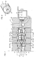
- the divider has two through holes 88 which receive end pins 89 secured to the resilient end cap 90 of the cylindrical sleeve 91 of a cartridge valve ( Figures 7 and 8).
- the sleeve is received by a suitable blind bore 92 in the valve block body 93 of a valve block 20.
- the valve sleeve 91 can be oriented with the inlet aperture 94, which is a circular segment matching a circular segment 81, 82 of the inlet aperture 80 of the block, either in communication with the low pressure inlet aperture 82 as shown or the cartridge can be rotated 180° with the pins 89 again inserted into the divider holes 88 to locate this inlet aperture 94 in communication with the high pressure inlet aperture 81.
- a chamber is accordingly defined including the aperture 94 in the end cap 90, the aligned hole 81 or 82 in the valve block and an internal cavity 95 in the sleeve 91.
- the cartridge valve will accordingly supply either high or low pressure air to a supply port 96 which is controlled by a solenoid 98 which is mounted on the solenoid mounting block portion 99 of the valve block.
- the solenoid mounting block portion clamps the cartridge valve within the blind bore 92 and hence, forces the resilient end cap 90 against the end of the blind bore to seal the operative inlet opening 81 or 82.
- the pilot air bore 86 extends through the valve block body and communicates with a pilot air line 100 in the solenoid mounting block portion which communicates with an air line 101 communicating with each cartridge valve via a solenoid 98 controlled seal 102. Should the illustrated pilot operated solenoids be replaced with solenoids not requiring pilot air, these pilot air lines could be eliminated.
- valve as used might be a normally open valve.
- Flow through these parallel conduits 110 can be controlled in a conventional manner with the use of full or half plugs and meter in or out check valves in one of these conduits and the selective use of a half plug or a needle valve, where required, in the other conduit.
- each valve block can be quickly and easily replaced with an identically configured valve block in the event a failure occurs.
- Each valve block is secured to the manifold with bolts 130 so that mechanical separation is quick and simple.
- the solenoids for each block are wired from a receptacle 132 secured to the block wiring harness 134.
- Electrical connection to the console is effected with a single quick release coupling 136 which can be released from the console and the three individual couplings 138 can be quickly released from the three valve block receptacles 132.
Landscapes
- Engineering & Computer Science (AREA)
- Chemical & Material Sciences (AREA)
- Physics & Mathematics (AREA)
- Manufacturing & Machinery (AREA)
- Materials Engineering (AREA)
- Organic Chemistry (AREA)
- Mechanical Engineering (AREA)
- General Physics & Mathematics (AREA)
- Automation & Control Theory (AREA)
- Valve Housings (AREA)
- Magnetically Actuated Valves (AREA)
- Re-Forming, After-Treatment, Cutting And Transporting Of Glass Products (AREA)
- Multiple-Way Valves (AREA)
Abstract
Description
- The present invention relates to I.S. (individual section) machines which make glass containers from molten gobs of glass.
- Each individual section of an I.S. machine has a blank side which forms a parison from the gob in a blank side mold and a blow side which forms the final glass container from the parison in a blow side mold. A number of movable mechanisms such as a blank side mold opening and closing mechanism, a plunger mechanism to be moved into a gob contained within the blank side mold, an invert mechanism for taking the formed parison and carrying it to the blow side, a blow side mold opening and closing mechanism, a takeout for removing the formed glass container from the blow side and depositing it on a dead plate and a pusher which will displace a bottle from the dead plate onto a conveyor are associated with each section and these mechanisms require air having a variety of pressures.
- To control the application of this air, each section has a valve block which supports a number of on/off valves which are operated by electronically controlled solenoids. A prior art valve block is shown in U.S. Patents numbered 3,918,489 and 4,382,451.
- It is an object of the present invention to provide an improved valve block for a section of an I.S. machine.
- The invention generally comprises a valve block assembly for controlling the flow of operating air to air operated mechanisms of a section of an I.S. machine comprising
at least one valve block including
a plurality of valves,
each of the valves having an inlet chamber for receiving operating air,
a conduit associated with each valve for directing operating air away from the valve towards an air operated mechanism or for directing exhaust air from the air operated mechanism to the valve, and
an exhaust channel for directing exhaust air away from the valves, and
a manifold including
means for supplying operating air to the inlet chambers,
an exhaust channel for receiving exhaust air from the valve block exhaust channel, and
a corresponding plurality of conduits communicating with the valve block conduits for delivering exhaust air from the air operated mechanisms to the valve block conduits or for directing operating air received from the valve block conduits towards the air operated mechanisms. - Other objects and advantages of the present invention will become apparent from the following portion of this specification and from the accompanying drawings which illustrate in accordance with the mandate of the patent statutes a presently preferred embodiment incorporating the principles of the invention.
- Referring to the drawings:
- Figure 1 is a schematic illustration of the valve block assembly made in accordance with the teachings of the present invention connected to an individual section of an I.S. machine;
- Figure 2 is a front view of the valve block manifold;
- Figure 3 is a view taken at 3-3 of Figure 2;
- Figure 4 is a view taken at 4-4 of Figure 2;
- Figure 5 is a view taken at 5-5 of Figure 2;
- Figure 6 is a rear view of a portion of one of the valve blocks which will engage the manifold;
- Figure 7 is a view taken at 7-7 of Figure 6;
- Figure 8 is an oblique view of one end of a valve cartridge used in the valve block;
- Figure 9 is a view taken at 9-9 of Figure 7;
- Figure 10 is a view taken at 10-10 of Figure 7;
- Figure 11 is a view taken at 11-11 of Figure 7; and
- Figure 12 is a front view of the electronics console and the valve blocks.
- Figure 1 is a schematic showing of a portion of one of the plurality (6,8,10,12, for example) of sections of an I.S. machine. The
section frame 10 supports a number of air operatedmechanisms air lines 12 for these mechanisms are connected to one or more "KISS"plates 13. High pressure P1, low pressure P2 and pilot air P3 are supplied throughpipes manifold 18 and from the manifold tovalve blocks 20. - While in the preferred embodiment, the manifold surface engages the surface of the kiss plates at one side of the kiss plates and discrete air lines are connected to the other side of the kiss plate, the kiss plates could be eliminated and the discrete air lines could be connected to the
conduits 70 of the manifold. High pressure P1, low pressure P2 and pilot air P3 are supplied throughpipes manifold 18 and from the manifold to thevalve blocks 20. This high and low pressure air is selectively redirected back to the manifold where it is directed through passages in the manifold to associated passages in the kiss plates and into theframe conduits 12. As shown, onemechanism 11A has two air lines and could, for example, include a three way valve, whereasmechanism 11B has only one air line and could, for example, include a pilot operated valve with either low pressure or high pressure air serving as this pilot air. Aconsole 22 is located above the valve blocks and houses the electronics for controlling the solenoid valves. Amachine stop button 24 and associatedmachine stop light 26 may be located on the front of the console. - Figure 2 is a front view of the manifold showing the surface on which the valve blocks are to be mounted. As can be seen, there are three horizontal rows of ten
exit apertures 30 each having upper 31 and lower 32 semi circular segments separated by adivider 33. Theupper exit apertures 31 of each row communicate with a horizontally extendinginternal chamber 34 which is supplied with high pressure air. Figure 3 shows how high pressure air is fed through anopening 35 in thebase 36 into a vertically extendingchannel 37 which communicates with thesehigh pressure chambers 34. - The
lower exit apertures 32 of the upper two rows communicate with horizontally extendinginternal chambers 38 which are supplied with low pressure air. Figure 3 also shows how low pressure air is fed through a base opening 39 into a vertically extendingchannel 40 which communicates with theselow pressure chambers 38. This verticallow pressure channel 40 also communicates with a horizontally extendingchamber 42 which communicates with the two low pressure exit apertures on the right hand end of the lowermost row. Aseparate chamber 44 communicates with the lower exit apertures of the two left hand apertures in the lowermost row and this chamber also is in communication with the low pressurevertical channel 40. - Referring to Figures 2 and 4, the lower exit aperture of each of the central six apertures of the lowermost row communicates with its own
vertical channel 50. These channels have a normallyopen opening 51 at the bottom and a pair of alignedholes front 54 and rear 55 channel walls. By plugging 56 both aligned holes of these six vertical channels and by connecting these channels through theopening 51 at the bottom to an independent pressure source, these channels can be connected to a pressure source having a pressure other than high and low pressure. Theseinlets 51 can accordingly be connected to a unique pressure such as plunger up pressure P4 or counterblow pressure P5. In the illustrated embodiment which is to control a triple gob machine, six special conduits are provided for the three plunger up lines and the three counterblow lines. Should special pressures not be required, thebottom holes 51 to these six (or any of them) can be plugged and the plugs in the rear walls 55 can be removed (access by removing the plug in the front wall) so that low pressure air from achamber 58 which is located behind thesechannels 50 and which communicates with the low pressurevertical channel 40, will enter theseindividual chambers 50 to supply the lower apertures with low pressure air. Pilot air (P3) is supplied to the valve blocks throughpiping 60 having anexit port 62 for each block and exhaust air exhausted from each block will be exhausted through avertical exhaust channel 64. - For every
exit aperture 30 in the manifold there is a conduit 70 (Figures 4 and 5) having anaperture 72 communicating with the front surface of the manifold and anaperture 74 communicating with one of therear surfaces kiss plate 13. The manifold (Figure 2) also has anopening 76 at the bottom front left which will receive an electronic receptacle with the cable passing through a channel in the manifold up to thetop chamber 78 so that the cable can be fed into the console through an opening at the rear of the console. Gaskets located between the mating surfaces of the kiss plates and the manifold and between the manifold and the valve blocks will effect the desired air tight seals. - Associated with each row of ten
exit apertures 30 is avalve block 20 having corresponding inlet apertures. As can be seen from Figure 6, which views a portion of the rear face of thevalve block 20 which is to engage the manifold, each valve block includesinlet apertures 80 having upper 81 and lower 82 semi circular segments separated by adivider 83, an inlet exit aperture 84, anexhaust channel 85 and a pilot bore 86 which will communicate respectively with the matchedexit apertures 30, inlet/exit aperture 72,pilot exit port 62 andexhaust channel 64 of the manifold. The divider has two throughholes 88 which receiveend pins 89 secured to theresilient end cap 90 of thecylindrical sleeve 91 of a cartridge valve (Figures 7 and 8). The sleeve is received by a suitable blind bore 92 in thevalve block body 93 of avalve block 20. Thevalve sleeve 91 can be oriented with theinlet aperture 94, which is a circular segment matching acircular segment inlet aperture 80 of the block, either in communication with the lowpressure inlet aperture 82 as shown or the cartridge can be rotated 180° with thepins 89 again inserted into the divider holes 88 to locate thisinlet aperture 94 in communication with the highpressure inlet aperture 81. A chamber is accordingly defined including theaperture 94 in theend cap 90, the alignedhole internal cavity 95 in thesleeve 91. The cartridge valve will accordingly supply either high or low pressure air to asupply port 96 which is controlled by asolenoid 98 which is mounted on the solenoid mountingblock portion 99 of the valve block. The solenoid mounting block portion clamps the cartridge valve within the blind bore 92 and hence, forces theresilient end cap 90 against the end of the blind bore to seal the operative inlet opening 81 or 82. The pilot air bore 86 extends through the valve block body and communicates with apilot air line 100 in the solenoid mounting block portion which communicates with anair line 101 communicating with each cartridge valve via asolenoid 98 controlledseal 102. Should the illustrated pilot operated solenoids be replaced with solenoids not requiring pilot air, these pilot air lines could be eliminated. When the solenoid is off, the cartridgevalve supply port 96 is closed and the cartridge valve exhaust port 104 is open. When the solenoid is operated the solenoid armature moves the seal to allow pilot air to operate the cartridge valve. When the solenoid is on, the valve element 105 is axially displaced from the illustrated position to its second position where the device port 104 is closed and thesupply port 96 is open. Pressurized air then passes through thesupply port 96 and throughsleeve apertures 106 into a kidney shaped chamber 108 (see also Figure 9) where it can flow throughparallel conduits 110 into another kidney shaped chamber 112 (see Figure 10) which surrounds the sleeve, leaving that chamber through aconduit 114 which is in communication with an associatedmanifold conduit 70. Optionally, the valve as used might be a normally open valve. Flow through theseparallel conduits 110 can be controlled in a conventional manner with the use of full or half plugs and meter in or out check valves in one of these conduits and the selective use of a half plug or a needle valve, where required, in the other conduit. - When the solenoid is off exhaust air will proceed from the
mechanism 11A, etc. through themanifold conduit 70, through theconduit 114 of the valve block into the first kidney shapedchamber 112, then through one or both of theparallel conduits 110 into the second kidney shapedchamber 108, through one set of sleeve holes 106 into thesleeve 91, through the exit port 104 of the cartridge valve, through a set ofexit apertures 116 in the sleeve to a channel 120 (Figure 11) which communicates with theexhaust channel 85. - Referring to Figure 12, each valve block can be quickly and easily replaced with an identically configured valve block in the event a failure occurs. Each valve block is secured to the manifold with
bolts 130 so that mechanical separation is quick and simple. The solenoids for each block are wired from areceptacle 132 secured to theblock wiring harness 134. Electrical connection to the console is effected with a singlequick release coupling 136 which can be released from the console and the threeindividual couplings 138 can be quickly released from the threevalve block receptacles 132. By removing thecoupling 138 from the valve block to be removed and theconsole coupling 136 in the event the upper valve block is to be removed, any valve block can be removed (and replaced) quickly and simply.
Claims (8)
- A valve block assembly for controlling the flow of operating air to air operated mechanisms of a section of an I.S. machine comprising
at least one valve block including
a plurality of valves,
each of said valves having an inlet chamber for receiving operating air,
a conduit associated with each valve for directing operating air away from said valve towards an air operated mechanisms or for directing exhaust air from the air operated mechanisms to said valve, and
an exhaust channel for directing exhaust air away from said valves, and
a manifold including
means for supplying operating air to said inlet chambers,
an exhaust channel for receiving exhaust air from said valve block exhaust channel, and
a corresponding plurality of conduits communicating with said valve block conduits for delivering exhaust air from the air operated mechanisms to said valve block conduits or for directing operating air received from said valve block conduits towards the air operated mechanisms. - A valve block assembly according to claim 1 wherein said manifold includes a planar mounting surface and said valve block body has a planar surface for engaging said mounting surface, and wherein said inlet chamber, exhaust channel and conduits of said valve block communicate with said valve block planar surface and said operating air supplying means, exhaust channel and conduits of said manifold communicate with said manifold planar surface, further comprising means for securing said valve block to said manifold with said surfaces in engagement to establish communication between said exhaust channels, between said conduits of said valve block and said conduits of said manifold and between said inlet chamber and said operating air supplying means.
- A valve block assembly according to claim 2, further comprising a corresponding plurality of solenoids for operating said valves, a wire harness connected to said solenoids, a receptacle connected to said wire harness and a releasable coupling connected to said receptacle.
- A valve block assembly according to claim 3 wherein said solenoids are pilot operated and further comprising a pilot air conduit in said valve block communicating with each of said solenoids and a pilot air conduit in said manifold for communicating with said valve block pilot air conduit for supplying pilot air to said solenoids.
- A valve block assembly according to claim 1 wherein said plurality of valves in each valve block are in a row and said plurality of conduits are in a row.
- A valve block assembly according to claim 5, comprising a plurality of valve blocks.
- A valve block assembly according to claim 1, wherein said manifold operating air supplying means comprises first conduit means for supplying operating air at one pressure and second conduit means for supplying operating air at a second pressure.
- A valve block assembly according to claim 7 wherein each of said valves can be oriented at two orientations to selectively alternately receive air from either one of said first and second conduit means.
Applications Claiming Priority (2)
| Application Number | Priority Date | Filing Date | Title |
|---|---|---|---|
| US48141 | 1993-04-15 | ||
| US08/048,141 US5435349A (en) | 1993-04-15 | 1993-04-15 | Valve block assembly for I.S. machine |
Publications (2)
| Publication Number | Publication Date |
|---|---|
| EP0620197A2 true EP0620197A2 (en) | 1994-10-19 |
| EP0620197A3 EP0620197A3 (en) | 1996-02-28 |
Family
ID=21952950
Family Applications (1)
| Application Number | Title | Priority Date | Filing Date |
|---|---|---|---|
| EP94302634A Withdrawn EP0620197A3 (en) | 1993-04-15 | 1994-04-13 | Valve block assembly for I.S. machine. |
Country Status (3)
| Country | Link |
|---|---|
| US (2) | US5435349A (en) |
| EP (1) | EP0620197A3 (en) |
| JP (1) | JPH0712260A (en) |
Cited By (3)
| Publication number | Priority date | Publication date | Assignee | Title |
|---|---|---|---|---|
| EP0884282A3 (en) * | 1997-06-10 | 1999-03-24 | BOTTERO S.p.A. | A method and electropneumatic valve unit for supplying air under pressure to a forming machine, particularly for forming glass articles |
| US7145173B2 (en) | 1994-04-22 | 2006-12-05 | Semiconductor Energy Laboratory Co., Ltd. | Semiconductor integrated circuit |
| EP2110561A1 (en) * | 2008-04-15 | 2009-10-21 | Festo AG & Co. KG | Electrical connecting unit and valve assembly fitted with the same |
Families Citing this family (9)
| Publication number | Priority date | Publication date | Assignee | Title |
|---|---|---|---|---|
| US7048007B2 (en) * | 1998-03-05 | 2006-05-23 | Swagelok Company | Modular surface mount manifold assemblies |
| CN1289851C (en) * | 1998-03-05 | 2006-12-13 | 斯瓦戈洛克公司 | Manifold system |
| US7036528B2 (en) | 1998-05-18 | 2006-05-02 | Swagelok Company | Modular surface mount manifold assemblies |
| US20040071927A1 (en) * | 2000-09-25 | 2004-04-15 | Murphy Peter Michael | Liquid impermeable barrier |
| US6872445B2 (en) | 2002-04-17 | 2005-03-29 | Invista North America S.A.R.L. | Durable, liquid impermeable and moisture vapor permeable carpet pad |
| US20060070674A1 (en) * | 2004-10-01 | 2006-04-06 | Eidsmore Paul G | Substrate with offset flow passage |
| KR102169315B1 (en) * | 2014-05-23 | 2020-10-23 | 두산인프라코어 주식회사 | Pilot signal block assembly for construction machinery and control valve assembly having the same |
| US12018765B2 (en) * | 2022-05-06 | 2024-06-25 | Sartorius Stedim Chromatography Systems Ltd. | Valve setup for SMB chromatography |
| US11879561B2 (en) * | 2022-05-20 | 2024-01-23 | Sartorius Stedim Chromatography Systems Ltd. | Valve setup for SMB chromatography |
Family Cites Families (11)
| Publication number | Priority date | Publication date | Assignee | Title |
|---|---|---|---|---|
| GB1415012A (en) * | 1972-06-23 | 1975-11-26 | Emhart Uk Ltd | Valve block |
| US4100937A (en) * | 1976-08-16 | 1978-07-18 | Owens-Illinois, Inc. | Valve block |
| DE2752938C2 (en) * | 1977-11-26 | 1985-06-20 | Bürkert GmbH, 7118 Ingelfingen | Control valve assembly for dental equipment |
| US4293004A (en) * | 1979-02-16 | 1981-10-06 | Ball Corporation | Electronic valve assembly for glassware forming machinery |
| US4382451A (en) * | 1979-02-16 | 1983-05-10 | Ball Corporation | Electronic valve assembly for glassware forming machinery |
| MX152277A (en) * | 1980-12-16 | 1985-06-19 | Vitro Tec Fideicomiso | IMPROVEMENTS IN SOLENOID PNEUMATIC VALVE BLOCKS FOR GLASS ARTICLE MANUFACTURING MACHINES |
| US4362544A (en) * | 1981-07-24 | 1982-12-07 | Owens-Illinois, Inc. | Fluid control system for glassware forming machine |
| DE3418933A1 (en) * | 1984-05-22 | 1985-11-28 | Robert Bosch Gmbh, 7000 Stuttgart | CONTROL VALVE |
| JPH0445217Y2 (en) * | 1987-04-30 | 1992-10-23 | ||
| IT1236747B (en) * | 1989-12-21 | 1993-03-31 | ELECTRO-PNEUMATIC VALVE BLOCK FOR CABLE GLASS FORMING MACHINES | |
| US5111840A (en) * | 1991-03-14 | 1992-05-12 | Applied Power Inc. | Modular valve |
-
1993
- 1993-04-15 US US08/048,141 patent/US5435349A/en not_active Expired - Fee Related
-
1994
- 1994-04-13 EP EP94302634A patent/EP0620197A3/en not_active Withdrawn
- 1994-04-14 JP JP6076127A patent/JPH0712260A/en active Pending
-
1995
- 1995-03-16 US US08/405,479 patent/US5531249A/en not_active Expired - Lifetime
Cited By (3)
| Publication number | Priority date | Publication date | Assignee | Title |
|---|---|---|---|---|
| US7145173B2 (en) | 1994-04-22 | 2006-12-05 | Semiconductor Energy Laboratory Co., Ltd. | Semiconductor integrated circuit |
| EP0884282A3 (en) * | 1997-06-10 | 1999-03-24 | BOTTERO S.p.A. | A method and electropneumatic valve unit for supplying air under pressure to a forming machine, particularly for forming glass articles |
| EP2110561A1 (en) * | 2008-04-15 | 2009-10-21 | Festo AG & Co. KG | Electrical connecting unit and valve assembly fitted with the same |
Also Published As
| Publication number | Publication date |
|---|---|
| EP0620197A3 (en) | 1996-02-28 |
| JPH0712260A (en) | 1995-01-17 |
| US5435349A (en) | 1995-07-25 |
| US5531249A (en) | 1996-07-02 |
Similar Documents
| Publication | Publication Date | Title |
|---|---|---|
| EP0620197A2 (en) | Valve block assembly for I.S. machine | |
| US5178191A (en) | Modular pneumatic control systems | |
| EP0754867A2 (en) | Chaine valve assembly | |
| US5699834A (en) | Manifold-type solenoid valves | |
| US6269834B1 (en) | Electromagnetically operated distribution valve for a pneumatic system | |
| US5660369A (en) | Pneumatic control device for needle valves in injection molding systems | |
| US4760961A (en) | Modular sprayhead assembly | |
| US4896700A (en) | Valve array | |
| US4557292A (en) | System for distributing pneumatic control signals by electrical means | |
| EP0620198B1 (en) | Valve block assembly for I.S. machine | |
| EP0704648B1 (en) | Switching valve | |
| GB1580692A (en) | Valve block | |
| US5996629A (en) | Pilot solenoid valve | |
| EP0621243B1 (en) | Valve block assembly for I.S. machine | |
| CN107816570A (en) | Fluid distributor device | |
| EP0675083A2 (en) | Valve block assembly for I.S. machine | |
| US3158164A (en) | Multiple block fluid distribution panel for mounting fluid control devices and method of directing fluid flow through the blocks | |
| KR20110089250A (en) | Vacuum controller | |
| EP1495246B1 (en) | Pneumatic valve and manifold mounting system | |
| US4382451A (en) | Electronic valve assembly for glassware forming machinery | |
| US5964244A (en) | Pilot-operated directional control valve | |
| EP0620199A2 (en) | Modular section control for I.S. machine | |
| EP0800002A1 (en) | Solenoid pilot valve | |
| JPH01216174A (en) | Shuttle valve device | |
| EP0490514A2 (en) | Plunger mechanism for I.S. machine |
Legal Events
| Date | Code | Title | Description |
|---|---|---|---|
| PUAI | Public reference made under article 153(3) epc to a published international application that has entered the european phase |
Free format text: ORIGINAL CODE: 0009012 |
|
| AK | Designated contracting states |
Kind code of ref document: A2 Designated state(s): DE FR GB IT |
|
| PUAL | Search report despatched |
Free format text: ORIGINAL CODE: 0009013 |
|
| AK | Designated contracting states |
Kind code of ref document: A3 Designated state(s): DE FR GB IT |
|
| 17P | Request for examination filed |
Effective date: 19960615 |
|
| 17Q | First examination report despatched |
Effective date: 19980616 |
|
| STAA | Information on the status of an ep patent application or granted ep patent |
Free format text: STATUS: THE APPLICATION HAS BEEN WITHDRAWN |
|
| 18W | Application withdrawn |
Withdrawal date: 19980925 |