EP0620302A1 - Kühlvorrichtung von einer Falschzwirntexturiermaschine - Google Patents
Kühlvorrichtung von einer Falschzwirntexturiermaschine Download PDFInfo
- Publication number
- EP0620302A1 EP0620302A1 EP94104608A EP94104608A EP0620302A1 EP 0620302 A1 EP0620302 A1 EP 0620302A1 EP 94104608 A EP94104608 A EP 94104608A EP 94104608 A EP94104608 A EP 94104608A EP 0620302 A1 EP0620302 A1 EP 0620302A1
- Authority
- EP
- European Patent Office
- Prior art keywords
- yarn
- cooling
- contacting
- cooling apparatus
- false
- Prior art date
- Legal status (The legal status is an assumption and is not a legal conclusion. Google has not performed a legal analysis and makes no representation as to the accuracy of the status listed.)
- Granted
Links
Images

Classifications
-
- D—TEXTILES; PAPER
- D02—YARNS; MECHANICAL FINISHING OF YARNS OR ROPES; WARPING OR BEAMING
- D02J—FINISHING OR DRESSING OF FILAMENTS, YARNS, THREADS, CORDS, ROPES OR THE LIKE
- D02J13/00—Heating or cooling the yarn, thread, cord, rope, or the like, not specific to any one of the processes provided for in this subclass
- D02J13/003—Heating or cooling the yarn, thread, cord, rope, or the like, not specific to any one of the processes provided for in this subclass by contact with at least one stationary surface, e.g. a plate
-
- D—TEXTILES; PAPER
- D02—YARNS; MECHANICAL FINISHING OF YARNS OR ROPES; WARPING OR BEAMING
- D02G—CRIMPING OR CURLING FIBRES, FILAMENTS, THREADS, OR YARNS; YARNS OR THREADS
- D02G1/00—Producing crimped or curled fibres, filaments, yarns, or threads, giving them latent characteristics
- D02G1/02—Producing crimped or curled fibres, filaments, yarns, or threads, giving them latent characteristics by twisting, fixing the twist and backtwisting, i.e. by imparting false twist
- D02G1/0206—Producing crimped or curled fibres, filaments, yarns, or threads, giving them latent characteristics by twisting, fixing the twist and backtwisting, i.e. by imparting false twist by false-twisting
- D02G1/0266—Producing crimped or curled fibres, filaments, yarns, or threads, giving them latent characteristics by twisting, fixing the twist and backtwisting, i.e. by imparting false twist by false-twisting false-twisting machines
Definitions
- the present invention relates to an improvement of a cooling apparatus of a false texturing machine, such as a draw texturing machine or a false twist texturing machine. More specifically, the present invention relates to a cooling apparatus of a false texturing machine, by which so called surging phenomenon can be prevented from occurring during high speed false twisting operation.
- the so called surging phenomenon means a phenomenon wherein a yarn generates a ballooning, i.e., a kind of rolling, of a yarn in a twisting zone when the false twist texturing speed is excessively increased, and abnormal variation in tension of the twisted yarn is resulted in.
- a false texturing machine comprises a false twisting device for imparting twists to a yarn, and a heating apparatus, disposed upstream the false twisting device, for heat setting twists run back along the yarn. Further, a draw texturing machine is provided with a drawing device for drawing the yarn at a predetermined draw ration prior to or simultaneously with the twist setting by the above-described heating apparatus and the false twisting device.
- a surging phenomenon i.e., a large waved vibration
- the yarn is subjected to a ballooning, i.e., rolling, in the twisting zone, and abnormal variation in tension of the twisted yarn occurs.
- a high temperature heating apparatus wherein a yarn is heated to a temperature higher than 300 o C, is used, unevenness in dyeing or yarn breakages may occur easily.
- the length of a cooling apparatus is shortened to about 500 mm, and two short cooling apparatus are prepared, and the yarn contacting surfaces of such cooling apparatus are forcedly cooled by means of cooling medium such as water.
- the construction of the cooling apparatus may be complicated if this measure is applied, and accordingly, the equipment cost and correspondingly the cost for manufacturing false textured yarns are increased.
- the present inventors have examined thoroughly in order to achieve the above-described object, and noticed that the object can be achieved by improving construction of the cooling apparatus. Thus, the present inventors have achieved the present invention.
- a false texturing machine comprising a false twisting device for imparting twists to a yarn, a heating apparatus, disposed upstream the false twisting device, for heat setting twists run back along the yarn, and a cooling apparatus, disposed between the heating apparatus and the false twisting device, for cooling the yarn
- the cooling apparatus comprises a yarn contacting and cooling surface, at least one non-contacting portions are partially disposed in the yarn contacting and cooling surface of the cooling apparatus, and pressing members, for pressing the yarn at the non-contacting portions, are disposed correspondingly to the non-contacting portions.
- the characteristic feature of the present invention resides in that non-contacting portions are partially formed in a yarn contacting and cooling surface of the cooling apparatus, and that the yarn is pressed at the non-contacting portions by means of pressing members. Since the yarn is in contact with the pressing members, which are disposed corresponding to the non-contacting portions, as described above, the pressing members serve as nodes of the vibration, i.e., the ballooning. Accordingly, the resonance frequency of the yarn at the yarn cooling zone is enhanced. As a result, the surging phenomenon does not occur easily. In addition, since the yarn is pressed at the non-contacting portions by means of the pressing members, the tension in yarn is enhanced. As a result, the resonance frequency of the yarn at the yarn cooling zone is also enhanced, and accordingly, the surging phenomenon does not occur easily.
- the present invention due to the prevention of occurrence of the surging phenomenon, the number of yarn breakages decreases as it will be confirmed by the example, and the crimp characteristic is increased.
- yarn having good quality and being free from unevenness in dyeing can be false textured at a super high speed higher than 1,000 m/min.
- the number of the non-contacting portions is set at least two as illustrated in the embodiment, and thus, the effect for preventing the surging phenomenon can be further enhanced.
- the respective yarn contacting and cooling surfaces divided by the non-contacting portions are formed in a convex shape, since the yarn runs in contact with the respective convex shaped yarn contacting and cooling surfaces divided by the non-contacting portions, and the effect for cooling the yarn is fully enhanced, and the tension in yarn can be maintained at a desired level.
- the yarn contacting and cooling surfaces are as a whole formed in a convex shape, since the yarn runs in contact with the convex shaped yarn contacting and cooling surfaces, and the effect for cooling the yarn is fully enhanced, and the tension in yarn can be maintained at a desired level.
- a length of a yarn contacting and cooling surface is between 100 and 500 mm, and a total length of a plurality of yarn contacting and cooling surfaces is between 1,000 and 3,000mm, and at least one of angles formed between a common imaginary contacting line for adjacent two yarn contacting and cooling surfaces divided by the non-contacting portion and a yarn pressed by the pressing member exceed 0 o and less than 30 o as shown in the embodiment.
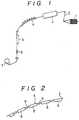
- Fig. 1 is a side view schematically illustrating a high speed false texturing machine
- a yarn 2 withdrawn from a supply package 1 is wound into a package by means of a take-up 7 after it passes a heating apparatus 3, cooling apparatus 4 and 5, and a false twisting device 6.
- Twists imparted by the false twisting device 6 run back along the yarn 2 towards the heating apparatus 3, and the twists are heat set by means of the heating apparatus 3 and the cooling apparatus 4 and 5. More specifically, heat setting is done by cooling the yarn 2, which has been heated by the heating apparatus 3, by means of the cooling apparatus 4 and 5.
- Fig. 2 is a side view of the cooling apparatus 4 illustrated in Fig. 1, and Fig. 3 is a partially enlarged view of Fig. 2.
- a plurality of partial cooling plates 8 and 8, which have a convex surface, respectively, are disposed in such a manner that they form a small distance therebetween, which distance forms a non-contacting portion, and that they as a whole form a convex shape.
- the cooling apparatus 4 is formed.
- the reason why a plurality of partial cooling plates 8 and 8 have a convex surface, respectively, and why the cooling apparatus formed by a plurality of partial cooling plates 8 and 8 as a whole form a convex shape is to enhance contacting efficiency of the yarn 2 to the partial cooling plates 8 and 8 and the cooling apparatus 4, and thus, to increase cooling efficiency and at the same time to maintain a desired tension in yarn.
- the required characteristics of the material suitable for the partial cooling plates 8 are that it can cool a yarn 2 quickly, that it is resistant to friction, that it has a low coefficient of friction against fibers and that its cost is inexpensive.
- steel plate may be used for such a cooling plate 8.
- yarn pressing members 9 are located beyond imaginary lines connecting the surfaces of the adjacent partial cooling plates 8 to positions under the surfaces of the partial cooling plates 8.
- the yarn pressing members 9 may be movable perpendicular to the yarn passage, and the yarn pressing member 9 may be moved from a operational position illustrated in Figs. 2 and 3 to a stand-by position, which is away from the operational position, upon threading so as to facilitate easy threading up to the cooling apparatus 4.
- the yarn pressing members 9 may be disposed at stationary positions at the small distance between the partial cooling plates 8 and 8, i.e., non-contacting portions, inserted beyond the yarn passage.
- Fig. 3 is an enlarged view illustrating the locational relationship between the partial cooling plate 8 and the yarn pressing member 9.
- the angle “a” and “b” denote the following amounts. More specifically, the angle “a” denotes an angle formed between a common imaginary contacting line 2' for the yarn contacting surfaces of adjacent two partial cooling plates 8 and a yarn leaving from one of the partial cooling plates to the pressing member 9, while the angle “b” denotes an angle formed between the common imaginary contacting line 2' for the yarn contacting surfaces of adjacent two partial cooling plates 8 and a yarn leaving from the pressing member 9 to the other partial cooling plates 8.
- the yarn pressing member 9 may be a stationary pin, and alternatively, it may be a turnable member, such as a roller, in some cases.
- the above-described cooling apparatus 4, i.e., the partial cooling plates 8, may be cooled by natural seasoning by means of radiation or convection, however, in some cases, it may be cooled by means of cooling medium, such as water or the like, if desired.
- the partial cooling plates 8 and 8 were separated and independent from each other.
- the partial cooling plates 8 may be formed integrally as illustrated in Fig. 4.
- the cooling apparatus 5 may be constructed in a manner similar to that of the cooling apparatus 4. In some cases, the cooling apparatus 5 may have a construction similar to a conventional one.
- the length of the cooling apparatus increases in order to surely cool a yarn.
- a yarn tends to generate ballooning at the cooling apparatus as described above.
- the surging phenomenon occurs as described above, and a stable texturing operation cannot be expected.
- the cooling apparatus is constructed with a combination of short partial cooling plates 8, and yarn pressing members 9 are disposed at non-contacting portions formed between the partial cooling plates 8.
- a yarn 2 is inserted by means of the yarn pressing members 9 to a position towards the inside of the partial cooling plates 8, i.e., lower position under the yarn contacting surfaces of the partial cooling plates 8, beyond the imaginary contacting line 2' connecting the yarn contacting surfaces of the partial cooling plate 8.
- the yarn 2 is pressed by means of the yarn pressing members 9 to a position opposite to the top of the convex shape formed by the partial cooling plate 8 relative to an imaginary curve along the yarn contacting surface of the convex shaped cooling apparatus 4.
- the curvature of the cooling apparatus 4 may be appropriately selected.
- the surging phenomenon can be prevented from occurring.
- the number of the yarn pressing members 9 increases if the length of the respective partial cooling plates 8 is shortened. If the number of the yarn pressing members 9 is excessively increased, run back of twists may be deteriorated or yarn breakages may occur easily.
- the length of the partial cooling plates 8 is shortened to an amount between 30 and 50 mm, that the number of the yarn pressing members 9 is increased, and that both the angles "a" and "b" are selected to a small amount, for example about 3 o .
- the length of the partial cooling plates 8 is at least about 100 mm, and the recommended maximum length is about 300 mm.
- the angles "a" and "b" have to be increased to a sufficiently large amount in order to achieve the effect for preventing the surging phenomenon, and as a result, frequency of yarn breakage increases.
- angles "a” and “b” exceed 0 o , effect can be observed, and it is confirmed that the preferred angles “a” and “b” are between 3 o and 30 o from good run back of twists and small yarn breakage. Especially, the most recommended angles “a” and “b” are between about 3 o and about 10 o . In this case, when the number of the yarn pressing members 9 increases, run back of twists is not disturbed, and a yarn is not damaged hardly, and therefore, occurrence of yarn breakages does not increase.
- the total length of the cooling apparatus 4 was 1,400 mm, and the radius of carvature was 4m.
- the cooling apparatus 4 was equally divided into 3, 5 and 8 partial cooling plates 8, In all the cases, the distance between the adjacent partial cooling plates 8 was 15 mm. Ceramic bars, having a diameter of 5mm, were prepared as yarn pressing members. Four levels, 0 o , 5 o , 10 o , 10 o , were prepared for the angle "a" and "b".
- the cooling apparatus 5, which was disposed downstream the cooling apparatus 4, was 300 mm long.
- the heating apparatus 3 was a high temperature heater of a non-contacting type, having 1,200 mm length and comprising two stages.
- the upper stage of the heating apparatus 3 was 400 mm long, and was always set to a temperature of 500 o C.
- the lower stage of the heating apparatus 3 was 800 mm long, and was set to a temperature of 300 o C at a texturing speed of 1,000 m/min, 360 o C at a texturing speed of 1,300 m/min, and 420 o C at a texturing speed of 1,600 m/min.
- the false twisting device was a false twisting device of a friction type.
- the supply yarn 1 was polyester POY, i.e., partially oriented yarn, of 115 de/36 fil, and was subjected to a simultaneous draw and texturing operation at draw ratio of 1.53. The results are shown in Table 1.
- non-contacting portions are partially formed in a yarn contacting and cooling surface, and the yarn is pressed at the non-contacting portions by means of pressing members. Since the yarn is in contact with the pressing members, which are disposed corresponding with the non-contacting portions, as described above, the pressing members serve as nodes of the vibration, i.e., the ballooning, and accordingly, the resonance frequency of the yarn at the yarn cooling zone is enhanced. As a result, the surging phenomenon does not occur easily. In addition, since the yarn is pressed at the non-contacting portions by means of the pressing members, the tension in yarn is enhanced. As a result, the resonance frequency of the yarn at the yarn cooling zone is also enhanced, and accordingly, the surging phenomenon does not occur easily.
- the present invention due to the prevention of occurrence of the surging phenomenon, the number of yarn breakages decreases, and the crimp characteristic is increased. Thus, yarn having good quality and being free from unevenness in dyeing can be false textured at a super high speed higher than 1,000 m/min.
Landscapes
- Engineering & Computer Science (AREA)
- Textile Engineering (AREA)
- Mechanical Engineering (AREA)
- Yarns And Mechanical Finishing Of Yarns Or Ropes (AREA)
- Structures Of Non-Positive Displacement Pumps (AREA)
Applications Claiming Priority (2)
| Application Number | Priority Date | Filing Date | Title |
|---|---|---|---|
| JP5098853A JP2598215B2 (ja) | 1993-03-31 | 1993-03-31 | 仮撚機の冷却装置 |
| JP98853/93 | 1993-03-31 |
Publications (2)
| Publication Number | Publication Date |
|---|---|
| EP0620302A1 true EP0620302A1 (de) | 1994-10-19 |
| EP0620302B1 EP0620302B1 (de) | 1997-09-17 |
Family
ID=14230794
Family Applications (1)
| Application Number | Title | Priority Date | Filing Date |
|---|---|---|---|
| EP94104608A Expired - Lifetime EP0620302B1 (de) | 1993-03-31 | 1994-03-23 | Kühlvorrichtung von einer Falschzwirntexturiermaschine |
Country Status (6)
| Country | Link |
|---|---|
| US (1) | US5438820A (de) |
| EP (1) | EP0620302B1 (de) |
| JP (1) | JP2598215B2 (de) |
| KR (1) | KR100231870B1 (de) |
| CN (1) | CN1034685C (de) |
| DE (1) | DE69405628T2 (de) |
Cited By (1)
| Publication number | Priority date | Publication date | Assignee | Title |
|---|---|---|---|---|
| FR2864111A1 (fr) * | 2003-12-18 | 2005-06-24 | Rieter Icbt | Dispositif de traitement thermique d'un fil textile en mouvement |
Families Citing this family (15)
| Publication number | Priority date | Publication date | Assignee | Title |
|---|---|---|---|---|
| JP2571180B2 (ja) * | 1992-12-08 | 1997-01-16 | 東洋電機株式会社 | 仮撚り加工用加熱装置 |
| CN1039142C (zh) * | 1993-06-15 | 1998-07-15 | 巴马格股份公司 | 人造丝加热器 |
| EP0691429B1 (de) * | 1994-06-22 | 1999-08-04 | B a r m a g AG | Heizschiene zur Erwärmung eines laufenden synthetischen Fadens |
| EP0705925B1 (de) * | 1994-10-07 | 2001-06-13 | B a r m a g AG | Heizeinrichtung mit auswechselbaren Fadenführern |
| DE59601849D1 (de) * | 1995-03-10 | 1999-06-17 | Barmag Barmer Maschf | Heizeinrichtung zum Erhitzen eines laufenden Fadens |
| TW317579B (de) * | 1995-04-11 | 1997-10-11 | Barmag Barmer Maschf | |
| EP0751245B1 (de) * | 1995-06-27 | 2002-11-27 | B a r m a g AG | Heizeinrichtung zum Erwärmen eines laufenden Fadens |
| TW386115B (en) * | 1996-04-08 | 2000-04-01 | Teijin Seiki Co Ltd | Yarn heating apparatus |
| JPH09273034A (ja) * | 1996-04-08 | 1997-10-21 | Teijin Seiki Co Ltd | 合成繊維糸条の熱処理装置 |
| GB9700436D0 (en) * | 1997-01-10 | 1997-02-26 | Rieter Scragg Ltd | Texturing yarn |
| AU5276499A (en) * | 1998-09-03 | 2000-03-27 | Retech Aktiengesellschaft | Texturing method |
| JP4060508B2 (ja) * | 2000-02-16 | 2008-03-12 | Tmtマシナリー株式会社 | 延伸仮撚加工機 |
| CN113049088B (zh) * | 2019-12-26 | 2025-02-28 | 宁波奥克斯电气股份有限公司 | 一种空调喘振状态检测装置 |
| CN112501736B (zh) * | 2020-11-02 | 2021-12-24 | 宜宾全联新材料科技有限公司 | 一种锦纶丝的加弹装置及其生产工艺 |
| JP7773939B2 (ja) * | 2022-04-15 | 2025-11-20 | Tmtマシナリー株式会社 | 加熱装置 |
Citations (3)
| Publication number | Priority date | Publication date | Assignee | Title |
|---|---|---|---|---|
| US3368335A (en) * | 1966-02-03 | 1968-02-13 | Heberlein & Co Ag | Apparatus for the treatment of yarns |
| CH583793A5 (en) * | 1975-04-18 | 1977-01-14 | Heberlein & Co Ag | Run quiescing device for false-twisted polyester multi-filament - with yarn guides extending along a curvilinear path along the yarn cooling zone |
| FR2451415A1 (fr) * | 1979-03-15 | 1980-10-10 | Astin France Assist Tech Indle | Dispositif de chauffage pour un materiau souple en defilement |
Family Cites Families (5)
| Publication number | Priority date | Publication date | Assignee | Title |
|---|---|---|---|---|
| JPS5212320A (en) * | 1975-07-14 | 1977-01-29 | Toyobo Co Ltd | Process for false twist texturing of synthetic filament yarns |
| CH617810B (de) * | 1978-04-19 | Rieter Ag Maschf | Verfahren und vorrichtung zum kuehlen eines fadens. | |
| JPS60108561A (ja) * | 1983-11-15 | 1985-06-14 | Nippon Denso Co Ltd | 燃料分配管 |
| DE59007713D1 (de) * | 1989-08-09 | 1994-12-22 | Barmag Barmer Maschf | Heizeinrichtung. |
| JP2871240B2 (ja) * | 1991-10-22 | 1999-03-17 | 村田機械株式会社 | 延伸仮撚機のクーリングプレート |
-
1993
- 1993-03-31 JP JP5098853A patent/JP2598215B2/ja not_active Expired - Lifetime
-
1994
- 1994-03-21 US US08/215,079 patent/US5438820A/en not_active Expired - Fee Related
- 1994-03-23 DE DE69405628T patent/DE69405628T2/de not_active Expired - Fee Related
- 1994-03-23 EP EP94104608A patent/EP0620302B1/de not_active Expired - Lifetime
- 1994-03-25 KR KR1019940006051A patent/KR100231870B1/ko not_active Expired - Fee Related
- 1994-03-30 CN CN94103802A patent/CN1034685C/zh not_active Expired - Fee Related
Patent Citations (3)
| Publication number | Priority date | Publication date | Assignee | Title |
|---|---|---|---|---|
| US3368335A (en) * | 1966-02-03 | 1968-02-13 | Heberlein & Co Ag | Apparatus for the treatment of yarns |
| CH583793A5 (en) * | 1975-04-18 | 1977-01-14 | Heberlein & Co Ag | Run quiescing device for false-twisted polyester multi-filament - with yarn guides extending along a curvilinear path along the yarn cooling zone |
| FR2451415A1 (fr) * | 1979-03-15 | 1980-10-10 | Astin France Assist Tech Indle | Dispositif de chauffage pour un materiau souple en defilement |
Cited By (1)
| Publication number | Priority date | Publication date | Assignee | Title |
|---|---|---|---|---|
| FR2864111A1 (fr) * | 2003-12-18 | 2005-06-24 | Rieter Icbt | Dispositif de traitement thermique d'un fil textile en mouvement |
Also Published As
| Publication number | Publication date |
|---|---|
| JP2598215B2 (ja) | 1997-04-09 |
| CN1096064A (zh) | 1994-12-07 |
| DE69405628T2 (de) | 1998-01-22 |
| KR100231870B1 (ko) | 1999-12-01 |
| DE69405628D1 (de) | 1997-10-23 |
| EP0620302B1 (de) | 1997-09-17 |
| JPH06287826A (ja) | 1994-10-11 |
| CN1034685C (zh) | 1997-04-23 |
| US5438820A (en) | 1995-08-08 |
| KR940021784A (ko) | 1994-10-19 |
Similar Documents
| Publication | Publication Date | Title |
|---|---|---|
| EP0620302B1 (de) | Kühlvorrichtung von einer Falschzwirntexturiermaschine | |
| US4567721A (en) | Method for producing textured yarn | |
| US3886722A (en) | Process for producing polyester textured yarn | |
| EP0332227B1 (de) | Berührungsloser Heizapparat für das Erwärmen eines synthetischen Garnes | |
| EP0644957B1 (de) | Verfahren zur herstellung von regelmässigen garnen über vermindertes zugkraftinduziertes abrutschen | |
| GB1525859A (en) | Yarn texturing | |
| EP0089005B1 (de) | Texturiertes Garn und Verfahren und Vorrichtung zur Herstellung desselben | |
| US5404706A (en) | Method of false twist texturing and a false twist texturing machine | |
| US3671623A (en) | Method of drawing and heat treating synthetic filaments | |
| EP0370816B1 (de) | Verfahren zur Herstellung von Polyesterfilamenten | |
| US6427300B2 (en) | Yarn relaxation-heating method and apparatus therefor | |
| US6705071B2 (en) | False-twist texturing method | |
| JPH09188925A (ja) | 仮撚機の二次ヒータ | |
| JPH01139838A (ja) | 高速仮撚り方法 | |
| JP2871240B2 (ja) | 延伸仮撚機のクーリングプレート | |
| US3035328A (en) | Method of preparing crimped yarns | |
| US3473317A (en) | Method for manufacturing crimped acrylonitrile filament yarn | |
| US3491524A (en) | Apparatus for false twisting filaments of thermoplastics fibers | |
| JP3830605B2 (ja) | 高速仮撚加工方法 | |
| JP2001336039A (ja) | 高速延伸仮撚加工方法及び高速延伸仮撚加工用非接触ヒーター | |
| JP2641337B2 (ja) | 高速仮撚加工方法 | |
| Yang | The Effect of Pre-heating in the False-twist Draw-texturing Process | |
| JP2001073239A (ja) | 高速延伸仮撚加工方法、ならびにそれに用いる高速延伸仮撚加工用非接触ヒーターおよび高速延伸仮撚加工装置 | |
| JPS61194232A (ja) | 仮撚加工機 | |
| JP2001011743A (ja) | 高速仮撚加工方法および高速仮撚加工用非接触ヒータ |
Legal Events
| Date | Code | Title | Description |
|---|---|---|---|
| PUAI | Public reference made under article 153(3) epc to a published international application that has entered the european phase |
Free format text: ORIGINAL CODE: 0009012 |
|
| AK | Designated contracting states |
Kind code of ref document: A1 Designated state(s): CH DE FR GB IT LI |
|
| 17P | Request for examination filed |
Effective date: 19941026 |
|
| 17Q | First examination report despatched |
Effective date: 19960902 |
|
| GRAG | Despatch of communication of intention to grant |
Free format text: ORIGINAL CODE: EPIDOS AGRA |
|
| GRAH | Despatch of communication of intention to grant a patent |
Free format text: ORIGINAL CODE: EPIDOS IGRA |
|
| GRAH | Despatch of communication of intention to grant a patent |
Free format text: ORIGINAL CODE: EPIDOS IGRA |
|
| GRAA | (expected) grant |
Free format text: ORIGINAL CODE: 0009210 |
|
| AK | Designated contracting states |
Kind code of ref document: B1 Designated state(s): CH DE FR GB IT LI |
|
| REG | Reference to a national code |
Ref country code: CH Ref legal event code: NV Representative=s name: BUGNION S.A. Ref country code: CH Ref legal event code: EP |
|
| REF | Corresponds to: |
Ref document number: 69405628 Country of ref document: DE Date of ref document: 19971023 |
|
| RIN2 | Information on inventor provided after grant (corrected) |
Free format text: NAKAHARA, TAKEICHI, C/O TEIJIN SEIKO CO., LTD. * HINO, HAJIME, C/O TEIJIN SEIKO CO., LTD. * IKEUCHI, TAKASHI, C/O TEIJIN SEIKO CO., LTD. * OGISO, TSUTOMU, C/O TEIJIN SEIKO CO., LTD. |
|
| ET | Fr: translation filed | ||
| ITF | It: translation for a ep patent filed | ||
| PLBE | No opposition filed within time limit |
Free format text: ORIGINAL CODE: 0009261 |
|
| 26N | No opposition filed | ||
| PGFP | Annual fee paid to national office [announced via postgrant information from national office to epo] |
Ref country code: GB Payment date: 19990112 Year of fee payment: 6 |
|
| PGFP | Annual fee paid to national office [announced via postgrant information from national office to epo] |
Ref country code: CH Payment date: 19990302 Year of fee payment: 6 |
|
| PGFP | Annual fee paid to national office [announced via postgrant information from national office to epo] |
Ref country code: FR Payment date: 19990326 Year of fee payment: 6 |
|
| PG25 | Lapsed in a contracting state [announced via postgrant information from national office to epo] |
Ref country code: GB Free format text: LAPSE BECAUSE OF NON-PAYMENT OF DUE FEES Effective date: 20000323 |
|
| PGFP | Annual fee paid to national office [announced via postgrant information from national office to epo] |
Ref country code: DE Payment date: 20000324 Year of fee payment: 7 |
|
| PG25 | Lapsed in a contracting state [announced via postgrant information from national office to epo] |
Ref country code: LI Free format text: LAPSE BECAUSE OF NON-PAYMENT OF DUE FEES Effective date: 20000331 Ref country code: CH Free format text: LAPSE BECAUSE OF NON-PAYMENT OF DUE FEES Effective date: 20000331 |
|
| GBPC | Gb: european patent ceased through non-payment of renewal fee |
Effective date: 20000323 |
|
| REG | Reference to a national code |
Ref country code: CH Ref legal event code: PL |
|
| PG25 | Lapsed in a contracting state [announced via postgrant information from national office to epo] |
Ref country code: FR Free format text: LAPSE BECAUSE OF NON-PAYMENT OF DUE FEES Effective date: 20001130 |
|
| REG | Reference to a national code |
Ref country code: FR Ref legal event code: ST |
|
| PG25 | Lapsed in a contracting state [announced via postgrant information from national office to epo] |
Ref country code: DE Free format text: LAPSE BECAUSE OF NON-PAYMENT OF DUE FEES Effective date: 20020101 |
|
| PG25 | Lapsed in a contracting state [announced via postgrant information from national office to epo] |
Ref country code: IT Free format text: LAPSE BECAUSE OF NON-PAYMENT OF DUE FEES;WARNING: LAPSES OF ITALIAN PATENTS WITH EFFECTIVE DATE BEFORE 2007 MAY HAVE OCCURRED AT ANY TIME BEFORE 2007. THE CORRECT EFFECTIVE DATE MAY BE DIFFERENT FROM THE ONE RECORDED. Effective date: 20050323 |