EP0620347B1 - Scharnieraufbau mit Drehzapfen - Google Patents
Scharnieraufbau mit Drehzapfen Download PDFInfo
- Publication number
- EP0620347B1 EP0620347B1 EP94302328A EP94302328A EP0620347B1 EP 0620347 B1 EP0620347 B1 EP 0620347B1 EP 94302328 A EP94302328 A EP 94302328A EP 94302328 A EP94302328 A EP 94302328A EP 0620347 B1 EP0620347 B1 EP 0620347B1
- Authority
- EP
- European Patent Office
- Prior art keywords
- pivot pin
- hinge member
- block portion
- bore
- hinge
- Prior art date
- Legal status (The legal status is an assumption and is not a legal conclusion. Google has not performed a legal analysis and makes no representation as to the accuracy of the status listed.)
- Expired - Lifetime
Links
Images
Classifications
-
- A—HUMAN NECESSITIES
- A47—FURNITURE; DOMESTIC ARTICLES OR APPLIANCES; COFFEE MILLS; SPICE MILLS; SUCTION CLEANERS IN GENERAL
- A47K—SANITARY EQUIPMENT; ACCESSORIES THEREFOR, e.g. TOILET ACCESSORIES
- A47K3/00—Baths; Showers; Appurtenances therefor
- A47K3/28—Showers or bathing douches
- A47K3/30—Screens or collapsible cabinets for showers or baths
- A47K3/36—Articulated screens
-
- E—FIXED CONSTRUCTIONS
- E05—LOCKS; KEYS; WINDOW OR DOOR FITTINGS; SAFES
- E05D—HINGES OR SUSPENSION DEVICES FOR DOORS, WINDOWS OR WINGS
- E05D5/00—Construction of single parts, e.g. the parts for attachment
- E05D5/02—Parts for attachment, e.g. flaps
- E05D5/0246—Parts for attachment, e.g. flaps for attachment to glass panels
-
- E—FIXED CONSTRUCTIONS
- E05—LOCKS; KEYS; WINDOW OR DOOR FITTINGS; SAFES
- E05D—HINGES OR SUSPENSION DEVICES FOR DOORS, WINDOWS OR WINGS
- E05D7/00—Hinges or pivots of special construction
- E05D7/08—Hinges or pivots of special construction for use in suspensions comprising two spigots placed at opposite edges of the wing, especially at the top and the bottom, e.g. trunnions
- E05D7/081—Hinges or pivots of special construction for use in suspensions comprising two spigots placed at opposite edges of the wing, especially at the top and the bottom, e.g. trunnions the pivot axis of the wing being situated near one edge of the wing, especially at the top and bottom, e.g. trunnions
-
- E—FIXED CONSTRUCTIONS
- E05—LOCKS; KEYS; WINDOW OR DOOR FITTINGS; SAFES
- E05F—DEVICES FOR MOVING WINGS INTO OPEN OR CLOSED POSITION; CHECKS FOR WINGS; WING FITTINGS NOT OTHERWISE PROVIDED FOR, CONCERNED WITH THE FUNCTIONING OF THE WING
- E05F1/00—Closers or openers for wings, not otherwise provided for in this subclass
- E05F1/08—Closers or openers for wings, not otherwise provided for in this subclass spring-actuated, e.g. for horizontally sliding wings
- E05F1/10—Closers or openers for wings, not otherwise provided for in this subclass spring-actuated, e.g. for horizontally sliding wings for swinging wings, e.g. counterbalance
- E05F1/12—Mechanisms in the shape of hinges or pivots, operated by springs
- E05F1/1246—Mechanisms in the shape of hinges or pivots, operated by springs with a coil spring perpendicular to the pivot axis
- E05F1/1253—Mechanisms in the shape of hinges or pivots, operated by springs with a coil spring perpendicular to the pivot axis with a compression spring
-
- E—FIXED CONSTRUCTIONS
- E05—LOCKS; KEYS; WINDOW OR DOOR FITTINGS; SAFES
- E05Y—INDEXING SCHEME ASSOCIATED WITH SUBCLASSES E05D AND E05F, RELATING TO CONSTRUCTION ELEMENTS, ELECTRIC CONTROL, POWER SUPPLY, POWER SIGNAL OR TRANSMISSION, USER INTERFACES, MOUNTING OR COUPLING, DETAILS, ACCESSORIES, AUXILIARY OPERATIONS NOT OTHERWISE PROVIDED FOR, APPLICATION THEREOF
- E05Y2800/00—Details, accessories and auxiliary operations not otherwise provided for
- E05Y2800/67—Materials; Strength alteration thereof
- E05Y2800/672—Glass
-
- E—FIXED CONSTRUCTIONS
- E05—LOCKS; KEYS; WINDOW OR DOOR FITTINGS; SAFES
- E05Y—INDEXING SCHEME ASSOCIATED WITH SUBCLASSES E05D AND E05F, RELATING TO CONSTRUCTION ELEMENTS, ELECTRIC CONTROL, POWER SUPPLY, POWER SIGNAL OR TRANSMISSION, USER INTERFACES, MOUNTING OR COUPLING, DETAILS, ACCESSORIES, AUXILIARY OPERATIONS NOT OTHERWISE PROVIDED FOR, APPLICATION THEREOF
- E05Y2900/00—Application of doors, windows, wings or fittings thereof
- E05Y2900/10—Application of doors, windows, wings or fittings thereof for buildings or parts thereof
- E05Y2900/114—Application of doors, windows, wings or fittings thereof for buildings or parts thereof for showers
Definitions
- This invention relates to hinge assemblies adapted for use with glass panes, used especially in shower doors and other glass structures.
- Document US-A-2 191 900 discloses a hinge assembly having the features of the preamble of claim 1.
- Hinge assemblies for glass doors are usually of the kind shown in US patent 5,079,798 issued 14 January 1992. Such hinge assemblies are placed on the edges of glass doors and are oriented in a vertical plane, to support the weight of the glass doors.
- a disadvantage of this type of hinge assembly is that it can exert undue stress on the glass, causing it to crack, and in addition it can be difficult to mount the fixed part of the hinge unless there is a sufficient structural support backing up the fixed part of the hinge.
- the fixed part of the hinge is usually attached through tile, marble or artificial stone, and unless there is a structural support behind this material, the fixed part of the hinge will not be adequately secured.
- the large hinges located along the height of the door are unsightly.
- hinges are placed at the bottom and top of a shower door or the like, with their pivot pins extending vertically toward the top and bottom edges of the door, as shown in US patent 4,035,957 issued 19 July 1977.
- the bottom hinge bears the weight of the door as a compressive force.
- the door is not hung on its edge, thereby reducing the likelihood that the door will crack.
- the hinges, being at the top and bottom of the door are somewhat out of the way visually and are usually less unsightly.
- US-A-2191900 shows a door hinge arrangement in which a pivot pin protrudes between a hinge containing a set of plates with a block between them to clamp the member being hinged but without any detent arrangement.
- GB-A-404854 shows a door hinge arrangement in which a pressure assembly pushes on a pivot pin to provide a detent action.
- a pressure assembly pushes on a pivot pin to provide a detent action.
- only a single pressure assembly is used, resulting in unbalanced forces, and only a small force can be achieved unless a large spring, which would be bulky and unsightly, is used.
- hinge assembly suitable for use as a top or bottom hinge for a glass door, and which hinge assembly can provide self closing forces which tend to close the door and hold it in a closed position.
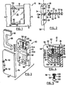
- Fig. 1 shows a shower stall generally indicated at 10.
- the shower stall 10 has a front bottom wall 12, front side walls 14, and a front upper glass wall 16 extending between the side walls 14.
- the walls 12, 14, 16 define an opening 18 which receives a shower door 20.
- the shower door 20 is pivotally mounted in the opening 18 by a bottom hinge 22 and a top hinge 24.
- Hinges 22, 24 both employ the features of the invention, and hinge 22 will next be described, with reference to Figs. 2 to 5.
- Hinge 22 includes a fixed hinge member 26, in the form of a flat relatively thin rectangular bar.
- Hinge member 26 includes a pair of screw holes 28 adapted to receive downwardly extending screws 30 (Fig. 1) to secure hinge member 26 to the upper surface 7 of bottom wall 12.
- Hinge member 26 also includes (Fig. 2) a central bore 34 extending from a rear surface 36 toward the front surface 38 of the hinge member 26.
- the bore 34 opens into a square recess 40 sunk into the centre of the front surface 38 of the hinge member 26.
- the pivot pin 46 includes a generally cylindrical shaft portion 48 extending from the square end 42 to a free end 50.
- the shaft portion 48 contains two flat surfaces 52, one on each side thereof, and extending over most of the length of the pivot pin 46 between the square end 42 and the free end 50.
- the flat surfaces 52 are interconnected by curved surfaces 53. Only a short portion of the length of the pivot pin 46 adjacent the free end 50, and a further short portion adjacent the square end 42, is fully cylindrical.
- the pivot shaft 46 contains an axial internal threaded bore 54 extending into its square end 42.
- the pivot shaft 46 is rigidly secured to the hinge member 26 by a countersunk screw 56 which extends from the rear side of hinge member 26 through bore 34 and into the bore 54.
- the pivot pin 46 will be oriented so that the flat surfaces 52 are perpendicular to the longitudinal axis 58 of the hinge member 26.
- the hinge member 60 includes a pair of plate members 62, 64 which are adapted to lie one on each side of a glass pane, a portion of which is shown at 65 in Fig. 3.
- the glass pane 65 forms part of the door 20 or other structure to be hinged.
- the hinge plate 62 includes side edges 66, and end edge 68, and a flat pivot edge 70A.
- the hinge plate 60 also includes an internal surface 72 having a block 74 mounted thereon and extending inwardly toward the internal surface 76 of the other hinge plate 64.
- the block 74 is recessed inwardly from the edges 66 and 68 but has a flat pivot end surface 70B which is flush with surface 70A to form a common flat pivot end surface 70.
- a bore 82 extends into the block 74 from flat end surface 70B, at right angles to flat end surface 70B.
- the bore 82 terminates at an inner end 83 spaced from the far end 84 of the block 74, as best shown in Fig. 4.
- the glass pane 65 contains a cutout 86 which follows the contour of block 74, so that in practice the hinge member 60 may be placed on one side of the glass pane 65 with the block 74 located in the cutout 86, and then the other hinge plate 64 may be placed on the other side of glass pane 65 and secured by screws 90 which extend through counter sunk holes 92 in plate 76 and into threaded holes 94 in block 74.
- the holes 94 are spaced one on each side of bore 82.
- block 74 includes two side surfaces 100, 102 which extend between the plates 62, 64 and extend parallel to the bore 82, at right angles to the end surface 70.
- Surface 100 contains two bores 104 extending into the block 74 at right angles to surface 100 and parallel to end surface 70.
- Two similar bores 110 extend into surface 102, also at right angles to surface 102 and parallel to end surface 70.
- the bores 104, 110 intersect bore 82 and are aligned with each other.
- pivot shaft 46 extends into the bore 82 so that its free end 50 is located adjacent the inner end 83 of bore 82 but is spaced therefrom by a plastic (e.g. nylon) cylindrical disk 114 (to avoid metal to metal contact).
- the pivot pin 46 can be inserted into hinge member 60 before or after pivot pin 46 is connected to hinge member 26.
- Each pressure assembly 118 is inserted into each bore 104, 110.
- Each pressure assembly 118 being a pressure pad means, includes (see also Fig. 5) a pad comprising plastic bushing 120 having an enlarged cylindrical end 122 and a central shaft 124 extending therefrom.
- a small coil spring 126 is placed over each shaft 124 to press the enlarged end 122 againstoneof the flat surfaces 52 of the pivot pin 46.
- the spring and bushing assemblies are held in position by insert screws 128 which are inserted into each of the threaded bores 104, 110.
- pivot shaft 46 is, as discussed, first inserted into bore 82.
- the pressure assemblies 118 are then inserted into the four bores 104, 110 and tightened (by turning the insert screws 128 into the bores) to apply the desired degree of pressure to pivot shaft 46.
- This can be tested by connecting hinge member 26 to the square end 42 of pivot shaft 46 (as shown in Fig. 2) and turning it relative to hinge member 60, to determine whether the detent and self closing force exerted by pressure assemblies 118 against pivot pin 46 is adequate.
- the bushing ends 122 prevent withdrawal of pivot pin 46 from bore 82, partly by friction, and partly because they obstruct withdrawal of cylindrical end 50 so long as they bear wholly or largely on the flat surfaces 52.
- the hinge member 60 is connected to the glass pane 65 as described. (Normally gaskets are located between each hinge plate 62, 64 and the glass surface.)
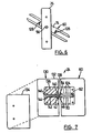
- the hinge members 26, 60 are then turned relative to each other, as shown in Fig. 6, to expose screw holes 28 so that the hinge member 26 can be connected e.g. to the top surface of bottom wall 12.
- the hinge members 26, 60 will typically be manufactured from a decorative material such as brass, anodized or powder coated aluminum, or stainless steel.
- the pivot pin 46 will normally be made of a strong material such as stainless steel, since it is in effect cantilevered and must withstand substantial forces.
- each side surface 100, 102 of the block 74 contains two bores, and because the bores are opposed, the block 74 can be made relatively thin and therefore more attractive, while still allowing sufficient force to be exerted on pivot pin 46. In addition, the opposing location of the bores balances the forces on pin 46 and aids in smoother operation.
- Hinge 24 includes a hinge member 60 identical with hinge member 60 of Fig. 3, but secured to the top of the door 20, and a fixed hinge member 130 secured to glass wall or plate 16.
- corresponding reference numerals indicate parts corresponding to those of Figs. 1 to 6 for the hinge member 60.
- the fixed hinge member 130 takes the form of two clamping plates 132, 134, of the same form as clamping plates 60, 64 and having a central block 136 therebetween also of the same form as block 74.
- hinge member 130 when hinge member 130 is mounted on glass, it will be indistinguishable visually from hinge member 60.
- block 136 has in its flat end surface 138 a square recess 140 adapted to receive the square end 42 of pivot pin 46.
- a bore 142 extends through block 136, aligned with bore 82, and terminates in a recessed enlarged end 144 adapted to receive an elongated screw 146.
- the screw 146 can therefore be inserted into bore 142 and into the threaded bore 54 in pivot pin 46, to secure the two hinge members 60, 130 together.
- hinge plate 134 is attached to hinge plate 132 as previously described, to secure the two hinge plates together.
Landscapes
- Health & Medical Sciences (AREA)
- Public Health (AREA)
- Engineering & Computer Science (AREA)
- Mechanical Engineering (AREA)
- Epidemiology (AREA)
- General Health & Medical Sciences (AREA)
- Hinges (AREA)
- Ladders (AREA)
- Securing Of Glass Panes Or The Like (AREA)
- Closing And Opening Devices For Wings, And Checks For Wings (AREA)
Claims (6)
- Scharnieranordnung für Glasscheiben, umfassend:a) ein erstes Scharnierelement (60), das ausgebildet ist, an der Glasscheibe (20) festgeklemmt zu werden und das umfaßt:einen ersten und einen zweiten Plattenabschnitt (62, 64) mit jeweils einer Stirnfläche (72, 76), die im Gebrauch einander gegenüber an einer jeweiligen Seite der Glasscheibe (20) anliegen, wobei die gegenüberliegenden Stirnflächen (72, 76) parallel zueinander und zur Ebene der Glasscheibe (20) liegen, wodurch eine Kante (70A) jedes Plattenabschnitts (62, 64) in einer gemeinsamen Ebene (70) im rechten Winkel zu den gegenüberliegenden Stirnflächen (72, 76) liegt,einen Blockabschnitt (74), der ausgebildet ist, zwischen den Plattenabschnitten (62, 64) zu liegen, wobei der Blockabschnitt (74) im Gebrauch mit den Plattenabschnitten (62, 64) verbunden und in einem Ausschnitt (86) der Glasscheibe (20) positioniert ist, wodurch eine ebene Endfläche (70B) des Blockabschnitts (74) in der gemeinsamen Ebene (70) liegt, wodurch die ebene Endfläche (70B) mit den Kanten (70A) des ersten und des zweiten Plattenabschnitts (62, 64) fluchtet, wobei der Blockabschnitt (74) eine erste und zweite Seitenfläche (100, 102) besitzt, die einander gegenüberliegen und sich im rechten Winkel zur ebenen Endfläche (70B) und zu den Ebenen der parallelen gegenüberliegenden Stirnflächen 872, 76) der Plattenabschnitte (62, 64) erstrecken,wobei der Blockabschnitt (74) kleinere seitliche Dimensionen aufweist als jene der Plattenabschnitte (62, 64), sodass die erste und die zweite Seitenfläche (100, 102) des Blockabschnitts (74), der mit dem ersten Plattenabschnitt (62) verbunden ist, von einer jeweiligen Seitenkante des ersten Plattenabschnitt (62) nach innen zurückversetzt sind,wobei der Blockabschnitt (74) eine erste Bohrung (82) aufweist, die sich in den Blockabschnitt (74) im rechten Winkel zu seiner ebenen Endfläche (70B) erstreckt, wobei die Bohrung (82) ein geschlossenes Innenende (83) besitzt,b) ein zweites Scharnierelement (26), das ausgebildet ist, mit einer Stützstruktur verbunden zu sein, und eine ebene Endfläche (38) besitzt, die im Gebrauch über der ebenen Endfläche (70B) des Blockabschnitts (74) liegt,c) einen Schwenkzapfen (46), der mit der Endfläche (38) des zweiten Scharnierelements (26) verbunden ist, aus dieser vorragt und im Gebrauch in die erste Bohrung (82) hineinragt,dadurch gekennzeichnet, dassd) der Blockabschnitt (74) eine zweite und dritte Gewindebohrung (104) in seiner ersten Seitenfläche (100) sowie eine vierte und fünfte Gewindebohrung (110) in seiner zweiten Seitenfläche (102) besitzt, wobei sich jede der zweiten bis fünften Bohrung (104, 110) im rechten Winkel zu ihrer jeweiligen Seitenfläche (100, 102) erstreckt und die erste Bohrung schneidet,e) der Schwenkzapfen (46) nichtdrehbar mit der Endfläche (38) des zweiten Scharnierelements verbunden ist und im Querschnitt gerundet ist, jedoch ein Paar gegenüberliegender ebener Oberflächenabschnitte (52), die sich parallel zur Drehzapfenachse erstrecken und ein freies Ende (50) aufweist, das angrenzend zum geschlossenen Innenende (83) des ersten Bohrung (82) angeordnet ist,f) ein Druckpuffermittel (118) in jeder der zweiten bis fünften Bohrung (104, 110) angeordnet ist, wobei jedes Paar Druckpuffermittel (118) in Bezug auf eine korrespondierende Seitenfläche (100, 102) elastisch in Angriff an einen jeweiligen ebenen Oberflächenabschnitt (52) des Drehzapfens (46) gedrückt wird, um den Drehzapfen (46) in eine ausgewählte Position relativ zum ersten Scharnierelement (60) vorzuspannen,g) jedes Druckpuffermittel (118) ein Federmittel (126) und ein einstellbares Schraubenmittel (128) enthält, um den Druck jedes Druckpuffermittels (118) auf den Drehzapfen (46) einzustellen.
- Anordnung nach Anspruch 1, worin das zweite Scharnierelement (26) ein im wesentlichen flacher Stab ist.
- Anordnung nach Anspruch 1, worin das zweite Scharnierelement (26) einen dritten und vierten Plattenabschnitt (32, 134) der gleichen Größe wie der erste bzw. zweite Plattenabschnitt (62, 64) und einen dazwischengelegenen Blockabschnitt (136) der gleichen Größe wie der erste Blockabschnitt (74) enthält.
- Anordnung nach einem der Ansprüche 1 bis 3, worin der Drehzapfen (46) ein quadratisches Ende (42) aufweist, wobei das zweite Scharnierelement (26) eine erste und eine zweite gegenüberliegende Oberfläche (38, 36) aufweist, wobei die erste Oberfläche (38) eine quadratische Ausnehmung (40) darin aufweist, wobei das quadratische Ende (42) ausgebildet ist, satt anliegend in die quadratische Ausnehmung (40) zu passen, wobei sich ein Schraubenmittel (56) von der zweiten Oberfläche (36) des zweiten Scharnierelements (26) durch das zweite Scharnierelement (26) hindurch in den Drehzapfen (46) erstreckt, wodurch dieser am zweiten Scharnierelement (26) befestigt wird.
- Anordnung nach einem der Ansprüche 1 bis 4, umfassend einen Kunststoffpuffer (114) zwischen dem freien Ende (50) des Drehzapfens (46) und dem Innenende (83) der ersten Bohrung (82).
- Anordnung nach einem der Ansprüche 1 bis 5, worin jedes Druckpuffermittel (118) eine Kunststoffmuffe (120), die ausgebildet ist, auf einen der ebenen Oberflächenabschnitte (52) des Drehzapfens (46) zu drücken, eine auf die Kunststoffmuffe (120) drückende Schraubenfeder (124) und eine Wurmschraube (128) aufweist, die die Schraubenfeder (124) und die Kunststoffmuffe (120) in der zweiten bis fünften Bohrung (104, 110) festhält.
Applications Claiming Priority (2)
| Application Number | Priority Date | Filing Date | Title |
|---|---|---|---|
| US08/045,751 US5297313A (en) | 1993-04-14 | 1993-04-14 | Pivot hinge assembly for glass structures |
| US45751 | 1993-04-14 |
Publications (2)
| Publication Number | Publication Date |
|---|---|
| EP0620347A1 EP0620347A1 (de) | 1994-10-19 |
| EP0620347B1 true EP0620347B1 (de) | 1997-08-06 |
Family
ID=21939674
Family Applications (1)
| Application Number | Title | Priority Date | Filing Date |
|---|---|---|---|
| EP94302328A Expired - Lifetime EP0620347B1 (de) | 1993-04-14 | 1994-03-31 | Scharnieraufbau mit Drehzapfen |
Country Status (5)
| Country | Link |
|---|---|
| US (1) | US5297313A (de) |
| EP (1) | EP0620347B1 (de) |
| AT (1) | ATE156558T1 (de) |
| CA (1) | CA2112794C (de) |
| DE (1) | DE69404720T2 (de) |
Cited By (1)
| Publication number | Priority date | Publication date | Assignee | Title |
|---|---|---|---|---|
| US7188390B2 (en) * | 2005-03-15 | 2007-03-13 | Ko-Ming Cheng | Adjustable hinge for a glass door |
Families Citing this family (27)
| Publication number | Priority date | Publication date | Assignee | Title |
|---|---|---|---|---|
| DE4428965A1 (de) * | 1994-08-16 | 1996-02-29 | Ernst Behm | Türscharnier mit integriertem Feststeller |
| US5867869A (en) * | 1994-10-06 | 1999-02-09 | Chmi | Pressure hinge device for glass door or panel |
| TW359713B (en) * | 1996-09-23 | 1999-06-01 | Fethers Glaingsystems Pty Ltd | Hinging and method of hinging glass shower door or like door |
| US6161255A (en) * | 1998-08-06 | 2000-12-19 | Chmi | Pressure hinge device for glass door or panel |
| US6363547B1 (en) | 2000-08-25 | 2002-04-02 | American Shower Door, Inc. | Apparatus for supporting bathing enclosure panels |
| US6526627B2 (en) * | 2000-12-05 | 2003-03-04 | Fanny Chiang | Hinge auto-return device for a glass door |
| US6560821B2 (en) | 2001-02-09 | 2003-05-13 | The Group Legacy L.C. | Glass door hinge |
| US6481055B2 (en) * | 2001-04-10 | 2002-11-19 | Ko Ming Cheng | Pivotal device for a frameless glass door |
| KR100452229B1 (ko) * | 2001-04-17 | 2004-10-08 | 류황명 | 글라스 도어의 고정장치 |
| US6648544B2 (en) * | 2001-12-08 | 2003-11-18 | Chan Hong Enterprise Co., Ltd. | Connector for glass |
| US6519811B1 (en) * | 2002-04-09 | 2003-02-18 | Ko-Ming Cheng | Pivot hinge assembly for glass structure |
| US6708369B1 (en) * | 2002-09-30 | 2004-03-23 | Shou-Hsing Liao | Adjustable top holder |
| US6704966B1 (en) * | 2002-10-30 | 2004-03-16 | Chin-Min Kao | Waterproof hinge structure for glass door |
| US20050125949A1 (en) * | 2003-12-10 | 2005-06-16 | Fang Tsan Co., Ltd. | Adjustable hinge for assembling a non-frame plate glass of a bathroom |
| US7814616B2 (en) * | 2004-08-10 | 2010-10-19 | Custom Hardware Mfg. Inc. | Pressure hinge device for glass door or panel |
| US7127777B2 (en) * | 2005-01-10 | 2006-10-31 | Fanny Chiang | Non-glass-cutting and adjustable automatic positioning hinge for a glass door |
| US7493673B2 (en) * | 2005-04-21 | 2009-02-24 | Custom Hardware Mfg. Inc. | Notchless glass plate clamp |
| SI22303A (sl) * | 2006-06-14 | 2007-12-31 | Alukomen Oprema D.D. | Okovje za steklena vrata in postopek izdelave le-tega |
| CA2638924C (en) * | 2007-09-13 | 2012-01-24 | Les Distributions Vimac Inc. | Pivot hinge assembly |
| US20140208543A1 (en) * | 2008-04-04 | 2014-07-31 | Correlated Magnetics Research, Llc. | Magnetic hinge system |
| AU2009250990B2 (en) * | 2009-01-12 | 2016-03-31 | Dias Aluminium Products Pty. Ltd. | Captive Pivot System For Shower Door And Head Frame |
| NL2005520C2 (nl) | 2010-10-14 | 2011-09-13 | Estem B V | Scharnier voor een paneeldeur, in het bijzonder voor een koelmeubel. |
| US8745822B2 (en) | 2011-02-07 | 2014-06-10 | Kl Megla Gmbh | Hinge joint |
| TW201326527A (zh) * | 2011-12-21 | 2013-07-01 | Gang Gwo Ind Co Ltd | 油壓鉸鍊 |
| WO2014169332A1 (en) * | 2013-04-15 | 2014-10-23 | Stuart Michael Christopher | A hinge |
| US20150216373A1 (en) * | 2014-01-31 | 2015-08-06 | J. Logan Pyeatt | Towel Access Shower Door |
| CN109779457A (zh) * | 2019-03-12 | 2019-05-21 | 福建西河卫浴科技有限公司 | 一种铰接装置和旋转淋浴房门 |
Family Cites Families (6)
| Publication number | Priority date | Publication date | Assignee | Title |
|---|---|---|---|---|
| GB404854A (en) * | 1933-05-12 | 1934-01-25 | John Robert Shattock | Improvements in or relating to hinges |
| US2191900A (en) * | 1938-11-26 | 1940-02-27 | Pariot George | Mounting for swinging closures |
| DE1196541B (de) * | 1960-08-29 | 1965-07-08 | Schoeninger Werkstaetten O H G | Beschlag fuer die Halterung von aus Glas bestehenden Fluegeln von Pendeltueren, Anschlagtueren, Trennwaenden od. dgl. |
| US3657766A (en) * | 1970-07-06 | 1972-04-25 | Hager & Sons Hinge Mfg | Hinge |
| DE2748623C2 (de) * | 1977-10-29 | 1984-04-05 | Vereinigte Glaswerke Gmbh, 5100 Aachen | Beschlag für eine rahmenlose Ganzglastür |
| US5079798A (en) * | 1990-08-13 | 1992-01-14 | Anthony Burke | Glass hinge assembly |
-
1993
- 1993-04-14 US US08/045,751 patent/US5297313A/en not_active Expired - Lifetime
-
1994
- 1994-01-04 CA CA002112794A patent/CA2112794C/en not_active Expired - Lifetime
- 1994-03-31 EP EP94302328A patent/EP0620347B1/de not_active Expired - Lifetime
- 1994-03-31 AT AT94302328T patent/ATE156558T1/de not_active IP Right Cessation
- 1994-03-31 DE DE69404720T patent/DE69404720T2/de not_active Expired - Fee Related
Cited By (1)
| Publication number | Priority date | Publication date | Assignee | Title |
|---|---|---|---|---|
| US7188390B2 (en) * | 2005-03-15 | 2007-03-13 | Ko-Ming Cheng | Adjustable hinge for a glass door |
Also Published As
| Publication number | Publication date |
|---|---|
| HK1001843A1 (en) | 1998-07-10 |
| DE69404720T2 (de) | 1998-01-22 |
| EP0620347A1 (de) | 1994-10-19 |
| CA2112794A1 (en) | 1994-10-15 |
| CA2112794C (en) | 1997-04-29 |
| ATE156558T1 (de) | 1997-08-15 |
| US5297313A (en) | 1994-03-29 |
| DE69404720D1 (de) | 1997-09-11 |
Similar Documents
| Publication | Publication Date | Title |
|---|---|---|
| EP0620347B1 (de) | Scharnieraufbau mit Drehzapfen | |
| US5079798A (en) | Glass hinge assembly | |
| US7594302B2 (en) | Pivot hinge assembly | |
| US5867869A (en) | Pressure hinge device for glass door or panel | |
| US5603142A (en) | Frame hinge | |
| US5500983A (en) | Corner cabinet hinge | |
| US6161255A (en) | Pressure hinge device for glass door or panel | |
| US6560821B2 (en) | Glass door hinge | |
| US5307539A (en) | Adjustable casement hinge | |
| US5058236A (en) | Adjustable hinge | |
| US4648152A (en) | Retractable door stop | |
| US20040020130A1 (en) | Adjustable automatic positioning hinge for a glass door | |
| US5067200A (en) | Hinge for inset doors | |
| NO165354B (no) | Doerhengsel for tunge doerer. | |
| CN101294468A (zh) | 门铰链 | |
| US3648327A (en) | Hinge set | |
| US5375296A (en) | Adjustable hinge and installation method for inset doors | |
| US4141109A (en) | Hinge support assembly | |
| US8863358B2 (en) | Adjustable hinge | |
| US5454144A (en) | Furniture hinge including base plate with claw member | |
| US5412840A (en) | Adjustable, furniture hinge having support arm with extensions engaging grooves in mounting plate | |
| US4332053A (en) | Concealed hinge for doors, flaps, or the like | |
| US5072488A (en) | Method and apparatus for mounting hinges to a door frame | |
| HK1001843B (en) | Pivot hinge assembly | |
| US6574836B1 (en) | Hinge friction device for barrel-type hinges |
Legal Events
| Date | Code | Title | Description |
|---|---|---|---|
| PUAI | Public reference made under article 153(3) epc to a published international application that has entered the european phase |
Free format text: ORIGINAL CODE: 0009012 |
|
| AK | Designated contracting states |
Kind code of ref document: A1 Designated state(s): AT BE CH DE DK ES FR GB IT LI NL PT SE |
|
| 17P | Request for examination filed |
Effective date: 19941004 |
|
| 17Q | First examination report despatched |
Effective date: 19951121 |
|
| GRAG | Despatch of communication of intention to grant |
Free format text: ORIGINAL CODE: EPIDOS AGRA |
|
| GRAH | Despatch of communication of intention to grant a patent |
Free format text: ORIGINAL CODE: EPIDOS IGRA |
|
| GRAH | Despatch of communication of intention to grant a patent |
Free format text: ORIGINAL CODE: EPIDOS IGRA |
|
| GRAA | (expected) grant |
Free format text: ORIGINAL CODE: 0009210 |
|
| AK | Designated contracting states |
Kind code of ref document: B1 Designated state(s): CH DE FR GB IT LI |
|
| REF | Corresponds to: |
Ref document number: 156558 Country of ref document: AT Date of ref document: 19970815 Kind code of ref document: T |
|
| RBV | Designated contracting states (corrected) |
Designated state(s): CH DE FR GB IT LI |
|
| REG | Reference to a national code |
Ref country code: CH Ref legal event code: NV Representative=s name: HEPP, WENGER & RYFFEL AG Ref country code: CH Ref legal event code: EP |
|
| REF | Corresponds to: |
Ref document number: 69404720 Country of ref document: DE Date of ref document: 19970911 |
|
| NLV5 | Nl: annulment (art. 75) | ||
| ET | Fr: translation filed | ||
| ITF | It: translation for a ep patent filed | ||
| PLBE | No opposition filed within time limit |
Free format text: ORIGINAL CODE: 0009261 |
|
| STAA | Information on the status of an ep patent application or granted ep patent |
Free format text: STATUS: NO OPPOSITION FILED WITHIN TIME LIMIT |
|
| 26N | No opposition filed | ||
| PGFP | Annual fee paid to national office [announced via postgrant information from national office to epo] |
Ref country code: GB Payment date: 20000329 Year of fee payment: 7 |
|
| PGFP | Annual fee paid to national office [announced via postgrant information from national office to epo] |
Ref country code: FR Payment date: 20000331 Year of fee payment: 7 |
|
| PGFP | Annual fee paid to national office [announced via postgrant information from national office to epo] |
Ref country code: CH Payment date: 20000522 Year of fee payment: 7 |
|
| PGFP | Annual fee paid to national office [announced via postgrant information from national office to epo] |
Ref country code: DE Payment date: 20000531 Year of fee payment: 7 |
|
| PG25 | Lapsed in a contracting state [announced via postgrant information from national office to epo] |
Ref country code: LI Free format text: LAPSE BECAUSE OF NON-PAYMENT OF DUE FEES Effective date: 20010331 Ref country code: GB Free format text: LAPSE BECAUSE OF NON-PAYMENT OF DUE FEES Effective date: 20010331 Ref country code: CH Free format text: LAPSE BECAUSE OF NON-PAYMENT OF DUE FEES Effective date: 20010331 |
|
| REG | Reference to a national code |
Ref country code: CH Ref legal event code: PL |
|
| GBPC | Gb: european patent ceased through non-payment of renewal fee |
Effective date: 20010331 |
|
| PG25 | Lapsed in a contracting state [announced via postgrant information from national office to epo] |
Ref country code: FR Free format text: LAPSE BECAUSE OF NON-PAYMENT OF DUE FEES Effective date: 20011130 |
|
| REG | Reference to a national code |
Ref country code: FR Ref legal event code: ST |
|
| PG25 | Lapsed in a contracting state [announced via postgrant information from national office to epo] |
Ref country code: DE Free format text: LAPSE BECAUSE OF NON-PAYMENT OF DUE FEES Effective date: 20020101 |
|
| PG25 | Lapsed in a contracting state [announced via postgrant information from national office to epo] |
Ref country code: IT Free format text: LAPSE BECAUSE OF NON-PAYMENT OF DUE FEES;WARNING: LAPSES OF ITALIAN PATENTS WITH EFFECTIVE DATE BEFORE 2007 MAY HAVE OCCURRED AT ANY TIME BEFORE 2007. THE CORRECT EFFECTIVE DATE MAY BE DIFFERENT FROM THE ONE RECORDED. Effective date: 20050331 |