EP0620357A2 - Revêtement d'un tunnel et méthode pour sa fixation - Google Patents
Revêtement d'un tunnel et méthode pour sa fixation Download PDFInfo
- Publication number
- EP0620357A2 EP0620357A2 EP94810210A EP94810210A EP0620357A2 EP 0620357 A2 EP0620357 A2 EP 0620357A2 EP 94810210 A EP94810210 A EP 94810210A EP 94810210 A EP94810210 A EP 94810210A EP 0620357 A2 EP0620357 A2 EP 0620357A2
- Authority
- EP
- European Patent Office
- Prior art keywords
- segments
- supports
- tunnel
- tunnel lining
- lining according
- Prior art date
- Legal status (The legal status is an assumption and is not a legal conclusion. Google has not performed a legal analysis and makes no representation as to the accuracy of the status listed.)
- Granted
Links
Images



Classifications
-
- E—FIXED CONSTRUCTIONS
- E21—EARTH OR ROCK DRILLING; MINING
- E21D—SHAFTS; TUNNELS; GALLERIES; LARGE UNDERGROUND CHAMBERS
- E21D11/00—Lining tunnels, galleries or other underground cavities, e.g. large underground chambers; Linings therefor; Making such linings in situ, e.g. by assembling
- E21D11/003—Linings or provisions thereon, specially adapted for traffic tunnels, e.g. with built-in cleaning devices
-
- E—FIXED CONSTRUCTIONS
- E21—EARTH OR ROCK DRILLING; MINING
- E21D—SHAFTS; TUNNELS; GALLERIES; LARGE UNDERGROUND CHAMBERS
- E21D11/00—Lining tunnels, galleries or other underground cavities, e.g. large underground chambers; Linings therefor; Making such linings in situ, e.g. by assembling
- E21D11/14—Lining predominantly with metal
- E21D11/18—Arch members ; Network made of arch members ; Ring elements; Polygon elements; Polygon elements inside arches
-
- E—FIXED CONSTRUCTIONS
- E21—EARTH OR ROCK DRILLING; MINING
- E21D—SHAFTS; TUNNELS; GALLERIES; LARGE UNDERGROUND CHAMBERS
- E21D11/00—Lining tunnels, galleries or other underground cavities, e.g. large underground chambers; Linings therefor; Making such linings in situ, e.g. by assembling
- E21D11/38—Waterproofing; Heat insulating; Soundproofing; Electric insulating
Definitions
- the present invention relates to a tunnel lining made of a plurality of rectangular segments.
- Tunnels in the ground or in the rock for motor vehicles or the railway are usually lined with concrete segments, which are separated by dilatation joints. It has been shown that over time, the concrete can be damaged by the temperature fluctuations during the winter and by the often prevailing high water pressure. In addition, there are the exhaust gases from vehicle traffic, such as Nitrogen oxides, which can attack the concrete, the steel reinforcement and the dilation joints filled with an elastomeric material with the formation of nitrous acid. The consequence of this is that the concrete becomes brittle and water can enter the tunnel. If erosion continues, the concrete will crack and parts of the concrete segments and rocks may fall onto the tunnel road.
- Nitrogen oxides which can attack the concrete, the steel reinforcement and the dilation joints filled with an elastomeric material with the formation of nitrous acid.
- plastic elements that are not backfilled with concrete is problematic because they can easily be damaged by falling stone or concrete lumps. This is to be expected if the plastic elements do not sufficiently insulate the rock behind, so that it is exposed to freezing / thawing cycles in winter. In the case of large plastic elements, there is also the risk that the segments at the rigid attachment points can be damaged over time by the vibrations and swings of the elements, caused by the vehicle traffic passing by.
- a tunnel lining should be able to prevent water from seeping into the tunnel through the rock or concrete.
- the joints between the elements are usually sealed by elastomeric sealing compounds, which are pressed into the joints.
- these sealing compounds have the disadvantage that they tend to tear off at the interfaces between concrete or plastic and sealing compound if the elements expand or shrink due to the temperature fluctuations.
- the tunnel lining should be particularly quick and easy to install. In addition, it should be resistant to environmental influences, insulating and waterproof. Furthermore, individual segments of the tunnel lining should be able to be replaced quickly and easily at any time.
- a row of supports is provided on both sides of the tunnel on the floor and at least one row of supports on the tunnel reveal, to which supports and / or supports two opposite ends of the segments are fastened.
- the supports and supports can be installed beforehand, so that the actual installation of the tunnel lining can then take place very quickly, since the positioning can already take place during the installation of the supports and supports. Since the beams and supports can have relatively small dimensions, only one side of the roadway has to be blocked in the tunnel. Individual segments can be quickly replaced because they are only attached in two places. This means that the exhaust air ducts and ducts that may be behind the tunnel lining are easily accessible at all times.
- This tunnel lining can be used for the renovation of old tunnels as well as for new tunnels.
- the segments are expediently flexibly connected to the supports and the supports.
- the segments are therefore advantageously not completely rigidly connected to the carrier, but can absorb certain changes in length and / or vibrations. This is important because it prevents damage to the segments.
- the segments with the supports are advantageously in releasable engagement. Because the segments can simply be hooked on or snapped onto the supports, for example additional fasteners can be dispensed with. The assembly can therefore be done very quickly.
- the segments are advantageously pivotable about the support during assembly or disassembly. This considerably simplifies assembly and disassembly, because during assembly a segment can first be hung or supported on the supports and then pivoted against the support.
- the segment expediently has a groove at the foot into which the support engages with an axis. This construction allows a side segment to be assembled to be simply hung on the base on the base, pivoted against the support arranged on the tunnel reveal and then fastened. Additional fasteners are therefore only required for fastening the segment on the ceiling. Conversely, however, it is also conceivable to first hang the segment on the ceiling-side support, to pivot it against the tunnel reveal and then to fix it to the support.
- an arcuate segment is provided which extends approximately from the ground to approximately the tunnel ridge.
- a tunnel can be lined with only a single segment shape. This is particularly efficient and saves money.
- only a support arranged on the tunnel ridge must be provided, to which two segments can be attached on the ceiling side.
- the segment expediently has such a dimension that it can be easily pivoted past the support, to which lighting can also be attached, during assembly or disassembly.
- a first and a second segment and two rows of mutually opposite beams are provided on the tunnel reveal, the first segment being fastened laterally to the supports and beams and the second segment each being fastened to two mutually opposite beams.
- This tunnel lining which can approximately form a rectangle in cross section, is advantageous in tunnels can be used in which exhaust air ducts, fans, etc. are provided in the space between the tunnel lining and the actual tunnel wall. Depending on the dimensions of the tunnel, however, more than two segment types can also be provided for lining the tunnel.
- Appropriate supports for fastening the segments have two stops and means for fastening the segments. These supports can be used to fix two segments each.
- the carriers also have the advantage that e.g. electrical installations such as cable ducts and lighting can be installed.
- the segments on the supports are advantageous e.g. held by profile rails or are clamped by such.
- the segments can have a bead or a groove which engages with the profiled rail, so that the segment is reliably fixed without having to be rigidly connected to the carrier. Thanks to this type of fastening, the segments can rest on the profile rail and are therefore flexibly or flexibly connected to the carrier. This allows temperature-related changes in length of the segments to be absorbed.
- the adjacent side edges of two abutting segments advantageously overlap at least partially. As a result, escaping water can be drained off behind the segments and the water cannot penetrate into the tunnel.
- Rubber buffers are advantageously provided at the contact points between the segments and the supports or supports. This can protect the segments from wear and damage.
- the rubber buffers help to compensate for temperature-related changes in length of the segments.
- vibrations of the segments caused by vehicle traffic can be dampened.
- the segments made of a glass fiber reinforced plastic are advantageous. produced. This enables particularly lightweight segments with good mechanical properties to be built.
- the plastic segments are not attacked by the car exhaust.
- the segments expediently have a core consisting of an insulation material which is embedded in the glass-fiber-reinforced plastic and forms a firm bond therewith. This corresponds to a sandwich construction.
- the mechanical properties of such segments are particularly good.
- the insulation core can prevent the rock or concrete behind the tunnel lining from freezing during the cold season. The erosion of the rock can be stopped.
- sealing profile with at least one sealing lip is advantageously provided, which seals the joints between the segments on at least one side.
- the joints between two segments can be sealed with such a sealing profile on the front or the back.
- This sealing profile can therefore also serve as a cold barrier.
- the sealing profile also has the advantage over the sealing compounds that it does not tear off when the width of the segments changes.
- sealing profiles are easier to replace than sealing compounds pressed into the joints.
- the sealing profile expediently has two outwardly curved sealing lips which are connected by a connecting web arranged in the middle. Due to the curvature of the sealing lips, there is a certain pre-tension and the sealing lips always lie against the segments in the assembled state. It has proven to be particularly advantageous if two arms, which protrude approximately at right angles and which center the assembled sealing profile in the middle of the gap, are attached to the connecting web. This allows the due to Temperature fluctuations caused changes in the width of the segments can be absorbed without fear of the sealing profile slipping.
- the segments can be used together with the described sealing profile in tunnel bends without any problems, since the wide sealing lips are also able to seal gaps between the segments.
- the tunnel lining can be installed by attaching at least one row of supports to the floor on both sides of the tunnel and at least one row to the tunnel reveal, then hooking a segment to be assembled with its bottom end to the support and around the support against the carrier is pivoted and flexibly connected to the carrier and that a segment that may be necessary for the formation of the tunnel ceiling is also flexibly fastened between two opposite carriers.
- This is a simple, inexpensive and, above all, quick method of applying a tunnel lining.
- the supports and brackets can be installed in advance without having to completely block vehicle traffic.
- the actual assembly of the segments can e.g. done from a vehicle. From the vehicle, the segments can be lowered onto the support, hooked in and pivoted against the supports, to which they can subsequently be clamped or hooked in flexibly. This allows the segments to absorb vibrations and / or changes in length.
- the elements do not have to be fastened by a large number of screws and the like, but rather can only be fastened in two places.
- the bottom-side attachment can be done simply by hanging the segment on the support. As soon as the segments are locked on the ceiling side, the segments can be attached appropriate training of the bottom-side connection can no longer be lifted from the support. So there are no additional fasteners on the bottom side.
- the joints between the segments are advantageously sealed by pulling a sealing profile into the joints.
- the sealing profile can seal the joints on the front and on the back. This is a simple and quick process to waterproof the joints. It is a great advantage that the sealing profile can be quickly replaced at any time. Due to the double-sided sealing of the joints, no cold bridge can arise at this point.
- the 1 shows a tunnel 10 with a tunnel lining consisting of individual segments 13.
- the segments 13 have a curvature which is adapted to the tunnel radius and extend from the floor 17 to just below the tunnel ridge 19.
- the segments 13 rest on a support 21 on the floor 17 and they are clamped or suspended on a support 23 on the tunnel wall 18.
- the carrier 23 can e.g. be fastened to the tunnel wall 18 by screws 27.
- the pivoting radius R of the segments 13 around the support 21 is such that the segments 13 can be pivoted past a light source 29 arranged on the carrier 23 without any problems.
- the segments 13 can, depending on whether the side edges are overlapping or not, be replaced individually or together with one or both adjacent segments 13.
- the tunnel lighting 29 does not need to be dismantled.
- FIG. 2 shows a further tunnel lining made of two different segments 11, 12.
- the segments 11, 12 are only slightly curved, and the tunnel lining has an approximately rectangular cross section.
- the segments 11, 12 are laterally fastened to the carriers 24 by means of the profiled rails 36, 38.
- Illumination 29 can also be arranged on the supports 24.
- This tunnel lining has the advantage that above the horizontal segment 12 there is still enough space for the Installation of exhaust air ducts, fans etc. remains. In the case of very wide tunnels, however, it is also conceivable to form the ceiling of the tunnel lining from two horizontal segments, which are held by two side beams and one beam arranged in the middle of the tunnel.
- the segments 11, 12, 13 are advantageously made of a glass fiber reinforced plastic. In addition, they have a core 31 made of an insulating material (FIGS. 3, 4, 7 and 8). As a result, the segments 11, 12, 13 are also effective protection against the cold and it can be prevented that e.g. the earth or rock masses behind the segments freeze and erode. The insulation material is firmly connected to the glass fiber reinforced plastic. This creates a sandwich structure that can withstand high loads.
- FIG. 3 shows two different embodiments of the ceiling-side connection point of the segments 11, 12, 13 on the carrier 23, 24 in greater detail.
- the carrier according to FIG. 3 is intended to fix a segment 13.
- the segments 11, 12 can also be fastened to a carrier 24 in the same or a similar manner.
- the segment 13 has a bead 33 at the end on the ceiling, which is surrounded by a rubber buffer 41 to avoid frictional damage at the connection point.
- the bead 33 with the rubber buffer 41 is supported by an angled profile rail 37 which is attached to the carrier 23 e.g. is fixed by screws 39, held.
- the bead 33 is extended upwards at the outer end by a web 35 (FIG. 3a).
- the upwardly projecting web 35 serves to fix the rubber buffer 41 and also prevents the segment 13 from being able to slip out of the clasp.
- FIG. 3b differs from FIG. 3a in that the end of the segment 13 'is S-shaped in longitudinal section, so that it has a groove-shaped indentation 30, 32 on both the top and the bottom.
- a profile rail 37' can engage in the indentation 32 and hold the segment 13 '.
- a rubber profile 42 encloses the outer end of the segment 13 'and also partially fills the upper indentation 30.
- the upper indentation 30 is expediently closed by the side walls of the segment 13 '. Lateral slipping of the segment 13 'can thereby be prevented.
- This design of the ceiling-side connection point has the advantage of a relatively large flexibility of the segment 13 'on the carrier 23 or 24.
- FIGS 4 and 5 show the bottom-side connection point of the segment 13 in more detail.
- the bottom end of the segment 13 is designed as a somewhat widespread foot 43 with a groove 45 running in the longitudinal direction.
- the trough 45 interacts with the support 21, which consists of an angle profile 47 and an axis 49 or a tube attached to it.
- the foot 43 of the segment 13 is also protected by a rubber buffer 53.
- the purpose of the rubber buffers 41, 53 is to provide cushioning and better support for the segments 13 and to prevent the plastic from grinding on the metal parts of the connection points, which would cause damage to the segments 13 over a long period of time.
- the groove 45 is expediently so deep that the segment 13 cannot be lifted out of the support 21 on the base side when there is an existing fixation on the carrier 23.
- the angle profile 47 can be fastened to the ground and, as shown in FIG. 4, can be embedded in the asphalt surface 51. But it is also conceivable to attach the support 21 to the tunnel reveal.
- the tube 49 has at each end a nozzle 50 which can engage in the tube opening of an adjacent support 21.
- a connector 50 can be used
- a movable tube can be provided, which can be fixed by a locking screw.
- FIG. 6 shows the carrier 23, which has a trapezoidal profile with stops 55 projecting outwards, against which the segments 13 can rest.
- the carrier 23 has bores 57, 59, which serve on the one hand for fastening it to the tunnel ceiling 25 and on the other hand for fixing the profiled rail 37 to the carrier 23.
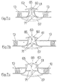
- FIG. 7 shows a sealing profile 63 for sealing the joint 61 between two segments 11, 12, 13.
- the sealing profile 63 closes the gap watertight on both the front and the back.
- the sealing profile 63 has two sealing lips 67, 69, each with an anchor or mushroom-shaped profile.
- the sealing lips 67, 69 are connected to one another in the middle by a connecting web 65 in such a way that the concave sides are oriented towards one another.
- the sealing lips 67, 69 are prestressed somewhat and are thereby pressed against the segments 11, 12, 13 to be sealed.
- Due to the wide sealing lips 67, 69, the joint 61 is also in the event of a change in its width, e.g. due to the shrinkage of the segments due to temperature cooling, still sealed watertight. (Fig.7 a) -c)).
- the joint 61 is sealed against the tunnel by the wider sealing lip 67 and against the tunnel reveal by the narrower sealing lip 69.
- two approximately horizontal arms 71 are attached to the connecting web 65 and center the sealing profile 63 in the middle of the joint 61.
- the arms 71 can expediently be inclined somewhat against the sealing lip 67. This can ensure that the arms 71 do not twist crosswise.
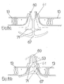
- FIG. 8 shows two possible types of mounting of the sealing profile 63. It has proven to be particularly useful if the sealing lip 69 before insertion into the Joint 61 is turned outwards and the sealing profile 63 is pressed into the joint 61 like a zipper (Fig. 8a). Another type of installation provides for the sealing profile 63 to be pushed into the joint 61 until the sealing lip 69 on the back of the segments 13 can relax again in the natural position (FIG. 8b, shown in broken lines).
- the side edges 14, 14 'of two adjacent segments 13' can also be designed to overlap, as shown in FIG.
- the two side edges 14, 14 'of a segment 13' can each be designed differently, i.e. one of the two side edges 14 has an outwardly projecting web 16 which can overlap an adjacent side edge 14 '.
- a sealing profile 40 which is drawn onto the side edge 14 ', seals the joint between the segments 13' at two points. At the same time, the sealing profile 40 prevents the segments from rubbing against one another.
- two segment types can be provided, each with different, mutually complementary side edges.
- the two segment types have to be installed alternately one after the other.
- the 10 shows how the assembly of the segments 13 of a vehicle 75 can take place.
- the vehicle 75 has a scaffold structure 77 with a work platform 79, from which the segments 13 can be attached to the carrier 23.
- the vehicle 75 can accommodate several segments 13 at the same time.
- the segments 11, 13 are supported on a ramp 81 of the vehicle 75 and are leaned against the bearing bracket 83 provided with a foam pad.
- At the rear of the vehicle 75 there is a traffic light 85 which draws the traffic's attention to the blocked lane.
- the tunnel 10 only has to be blocked in half during the renovation work.
- a device for producing the segments 11, 12, 13 has a rail and at least one carriage which can be moved along the rail.
- the rail and carriage are spaced and parallel to one another during manufacture, as required for the manufacture of the segments, i.e. seen from the side, the rail is curved like the segments to be manufactured.
- the carriage has several spaced openings or outlets for the synthetic resin to be applied on the underside.
- a scooter can be attached to another car. This is used to roll up and distribute the synthetic resin.
- a plurality of pistons are also provided at a distance from the mold and are used to press on the rigid foam plastic plates.
- the pistons can e.g. be lowered pneumatically so that they can rest on the mold. In order to generate a uniform contact pressure, the pistons have a e.g. rectangular plate on. Radiant heating can be provided above and below the molds in order to accelerate the manufacturing effort.
- a mold corresponding to the segments to be manufactured is first provided with a suitable release agent.
- the car is then moved over the mold and a so-called “gel coat” is applied evenly.
- the “gelcoat” forms a weatherproof and impermeable outer layer.
- a layer of polyester synthetic resin is applied evenly to the mold in the same way and a glass fiber mat is immediately worked into the liquid synthetic resin by moving the carriage back and forth with the roller. This ensures that the glass fiber mat is completely and uniformly saturated with the synthetic resin.
- a rigid foam plastic plate (eg made of polyurethane foam) is then placed on the glass fiber mat and pressed onto the mold by lowering the pistons onto the mold and pressing them onto the plastic plates.
- a second layer of synthetic resin is applied and another glass fiber mat is incorporated. This is followed by a waterproof top coat on the synthetic resin layer. Then let the resin harden.
- One-piece plastic segments can be produced by this manufacturing process. Prepared profiles, which interact with the supports, can be connected to the synthetic resin-glass fiber layers to reinforce the foot area. The individual phases of production can be accelerated by radiant heating.
Landscapes
- Engineering & Computer Science (AREA)
- Mining & Mineral Resources (AREA)
- Structural Engineering (AREA)
- Architecture (AREA)
- Civil Engineering (AREA)
- Life Sciences & Earth Sciences (AREA)
- General Life Sciences & Earth Sciences (AREA)
- Geochemistry & Mineralogy (AREA)
- Geology (AREA)
- Lining And Supports For Tunnels (AREA)
Applications Claiming Priority (3)
| Application Number | Priority Date | Filing Date | Title |
|---|---|---|---|
| CH112293 | 1993-04-14 | ||
| CH1122/93 | 1993-04-14 | ||
| CH112293 | 1993-04-14 |
Publications (3)
| Publication Number | Publication Date |
|---|---|
| EP0620357A2 true EP0620357A2 (fr) | 1994-10-19 |
| EP0620357A3 EP0620357A3 (fr) | 1995-05-31 |
| EP0620357B1 EP0620357B1 (fr) | 2002-01-09 |
Family
ID=4203009
Family Applications (1)
| Application Number | Title | Priority Date | Filing Date |
|---|---|---|---|
| EP94810210A Expired - Lifetime EP0620357B1 (fr) | 1993-04-14 | 1994-04-13 | Revêtement d'un tunnel et méthode pour sa fixation |
Country Status (3)
| Country | Link |
|---|---|
| EP (1) | EP0620357B1 (fr) |
| AT (1) | ATE211799T1 (fr) |
| DE (1) | DE59410024D1 (fr) |
Cited By (7)
| Publication number | Priority date | Publication date | Assignee | Title |
|---|---|---|---|---|
| EP0845579A1 (fr) | 1996-12-02 | 1998-06-03 | Xaver Jehle | Revêtement de tunnels |
| WO2001051769A1 (fr) * | 2000-01-11 | 2001-07-19 | Nordmarkens Betongprodukter Aktiebolag | Element de construction en forme d'arc |
| FR2883598A1 (fr) * | 2005-03-23 | 2006-09-29 | Gcc Soc Par Actions Simplifiee | Panneau de parement pour tunnel. |
| CN107034916A (zh) * | 2017-04-19 | 2017-08-11 | 中国铁道科学研究院铁道建筑研究所 | 玻璃纤维复合增强塑料预制装配结构 |
| CN110593914A (zh) * | 2019-09-19 | 2019-12-20 | 北京市政建设集团有限责任公司 | 一种暗挖地铁车站侧墙防水逆作缝的施工方法 |
| CN111648793A (zh) * | 2020-04-24 | 2020-09-11 | 高军 | 一种小净距重叠隧道施工方法 |
| CN121296143A (zh) * | 2024-07-09 | 2026-01-09 | 中国石油天然气管道工程有限公司 | 一种油气管道钻爆法隧道穿越活动断裂带连接结构 |
Families Citing this family (3)
| Publication number | Priority date | Publication date | Assignee | Title |
|---|---|---|---|---|
| CN109780999B (zh) * | 2018-12-18 | 2021-03-26 | 杭州国电大坝安全工程有限公司 | 隧洞内边壁测点坐标信息采集方法 |
| CN111828036B (zh) * | 2020-08-04 | 2022-04-08 | 开平市中立德路桥设备有限公司 | 一种隧道支护结构 |
| CN111828014B (zh) * | 2020-08-04 | 2022-10-28 | 云南建投矿业工程有限公司 | 一种隧道施工方法 |
Family Cites Families (3)
| Publication number | Priority date | Publication date | Assignee | Title |
|---|---|---|---|---|
| US1785096A (en) * | 1928-07-14 | 1930-12-16 | Commercial Shearing | Tunnel |
| FR685011A (fr) * | 1929-11-15 | 1930-07-03 | Queens Sohne & Comp | Construction de cadres de boisage |
| DE3027661C2 (de) * | 1980-07-22 | 1982-09-23 | Bochumer Eisenhütte Heintzmann GmbH & Co, 4630 Bochum | Streckenausbau zum Abfangen der Hangendschichten und zum Sichern des Streckensaums in Abbaustrecken des untertägigen Bergbaus |
-
1994
- 1994-04-13 DE DE59410024T patent/DE59410024D1/de not_active Expired - Fee Related
- 1994-04-13 EP EP94810210A patent/EP0620357B1/fr not_active Expired - Lifetime
- 1994-04-13 AT AT94810210T patent/ATE211799T1/de not_active IP Right Cessation
Cited By (8)
| Publication number | Priority date | Publication date | Assignee | Title |
|---|---|---|---|---|
| EP0845579A1 (fr) | 1996-12-02 | 1998-06-03 | Xaver Jehle | Revêtement de tunnels |
| WO2001051769A1 (fr) * | 2000-01-11 | 2001-07-19 | Nordmarkens Betongprodukter Aktiebolag | Element de construction en forme d'arc |
| FR2883598A1 (fr) * | 2005-03-23 | 2006-09-29 | Gcc Soc Par Actions Simplifiee | Panneau de parement pour tunnel. |
| CN107034916A (zh) * | 2017-04-19 | 2017-08-11 | 中国铁道科学研究院铁道建筑研究所 | 玻璃纤维复合增强塑料预制装配结构 |
| CN110593914A (zh) * | 2019-09-19 | 2019-12-20 | 北京市政建设集团有限责任公司 | 一种暗挖地铁车站侧墙防水逆作缝的施工方法 |
| CN111648793A (zh) * | 2020-04-24 | 2020-09-11 | 高军 | 一种小净距重叠隧道施工方法 |
| CN111648793B (zh) * | 2020-04-24 | 2022-03-04 | 高军 | 一种小净距重叠隧道施工方法 |
| CN121296143A (zh) * | 2024-07-09 | 2026-01-09 | 中国石油天然气管道工程有限公司 | 一种油气管道钻爆法隧道穿越活动断裂带连接结构 |
Also Published As
| Publication number | Publication date |
|---|---|
| EP0620357A3 (fr) | 1995-05-31 |
| EP0620357B1 (fr) | 2002-01-09 |
| ATE211799T1 (de) | 2002-01-15 |
| DE59410024D1 (de) | 2002-02-14 |
Similar Documents
| Publication | Publication Date | Title |
|---|---|---|
| DE19501384C9 (de) | Dichtungsvorrichtung zum Abdichten von Betonierfugen | |
| WO1987004478A1 (fr) | Pieces de fixation pour structures coffrees en beton | |
| DE2002296A1 (de) | Fugendichtung | |
| EP0620357B1 (fr) | Revêtement d'un tunnel et méthode pour sa fixation | |
| DE7624329U1 (de) | Dehnungsfugenbausatz | |
| DE2503590B2 (de) | Bahnoberbau mit gleistragplatten aus stahlbeton | |
| DE3634116A1 (de) | Dichtungsanordnung fuer bauwerke | |
| DE10158720C2 (de) | Fahrbahnplatte für Gleisanlagen | |
| DE3326430A1 (de) | Wiederverwendbare schalung fuer den verbundausbau und hinterfuellverfahren | |
| EP0889170A1 (fr) | Chaussée inerte et étanche aux liquides et procédé de réalisation | |
| DE2427746A1 (de) | System zum verschalen von teilen von gebaeuden | |
| DE3036620C2 (de) | Vorrichtung zum Schutz von Bauwerksteilen aus Beton gegen Feuchtigkeit | |
| DE3626074C2 (fr) | ||
| DE3924578C2 (de) | Fassadenwand | |
| DE2353611A1 (de) | Verankerung einer angemoertelten wandbekleidung | |
| DE1959941U (de) | Fugenbewehrungsvorrichtung fuer betonfahrbahndecken od. dgl. | |
| DE29917587U1 (de) | Einfassungselemente mit oder ohne Bandenaufbau für Roll- und Eishockey im Sport- und Spielbereich | |
| DE2119250C (de) | Randdichtung für eine Fahrbahnplatte | |
| DE2949963C2 (de) | Verfahren zum Ausbessern und Verstärken von Streckenausbau und dafür geeignete Verzugmatte | |
| DE3414764A1 (de) | Kanalsohlen-innenschale | |
| AT375699B (de) | Schienenanordnung, insbesondere fuer strassenbahn- gleise | |
| DE3143476A1 (de) | Randstein zur befestigung von kunstrasen | |
| DE8809408U1 (de) | Abflußrinnenelement für Entwässerungsanlagen | |
| DE1923696A1 (de) | Dichteinrichtung fuer Dehnungsfuge | |
| DE102024130422A1 (de) | Ingenieurbauwerk für Verkehrsanlagen |
Legal Events
| Date | Code | Title | Description |
|---|---|---|---|
| PUAI | Public reference made under article 153(3) epc to a published international application that has entered the european phase |
Free format text: ORIGINAL CODE: 0009012 |
|
| AK | Designated contracting states |
Kind code of ref document: A2 Designated state(s): AT CH DE FR IT LI |
|
| PUAL | Search report despatched |
Free format text: ORIGINAL CODE: 0009013 |
|
| RHK1 | Main classification (correction) |
Ipc: E21D 11/00 |
|
| AK | Designated contracting states |
Kind code of ref document: A3 Designated state(s): AT CH DE FR IT LI |
|
| 17P | Request for examination filed |
Effective date: 19960108 |
|
| 17Q | First examination report despatched |
Effective date: 20000302 |
|
| GRAG | Despatch of communication of intention to grant |
Free format text: ORIGINAL CODE: EPIDOS AGRA |
|
| GRAG | Despatch of communication of intention to grant |
Free format text: ORIGINAL CODE: EPIDOS AGRA |
|
| GRAH | Despatch of communication of intention to grant a patent |
Free format text: ORIGINAL CODE: EPIDOS IGRA |
|
| GRAH | Despatch of communication of intention to grant a patent |
Free format text: ORIGINAL CODE: EPIDOS IGRA |
|
| GRAA | (expected) grant |
Free format text: ORIGINAL CODE: 0009210 |
|
| AK | Designated contracting states |
Kind code of ref document: B1 Designated state(s): AT CH DE FR IT LI |
|
| PG25 | Lapsed in a contracting state [announced via postgrant information from national office to epo] |
Ref country code: FR Free format text: LAPSE BECAUSE OF FAILURE TO SUBMIT A TRANSLATION OF THE DESCRIPTION OR TO PAY THE FEE WITHIN THE PRESCRIBED TIME-LIMIT Effective date: 20020109 |
|
| REF | Corresponds to: |
Ref document number: 211799 Country of ref document: AT Date of ref document: 20020115 Kind code of ref document: T |
|
| REG | Reference to a national code |
Ref country code: CH Ref legal event code: EP |
|
| REF | Corresponds to: |
Ref document number: 59410024 Country of ref document: DE Date of ref document: 20020214 |
|
| EN | Fr: translation not filed | ||
| PLBE | No opposition filed within time limit |
Free format text: ORIGINAL CODE: 0009261 |
|
| STAA | Information on the status of an ep patent application or granted ep patent |
Free format text: STATUS: NO OPPOSITION FILED WITHIN TIME LIMIT |
|
| REG | Reference to a national code |
Ref country code: CH Ref legal event code: PL |
|
| 26N | No opposition filed | ||
| REG | Reference to a national code |
Ref country code: CH Ref legal event code: NV Representative=s name: RIEDERER HASLER & PARTNER PATENTANWAELTE AG Ref country code: CH Ref legal event code: AEN Free format text: DAS PATENT IST AUFGRUND DES WEITERBEHANDLUNGSANTRAGS VOM 24.01.2003 REAKTIVIERT WORDEN. |
|
| REG | Reference to a national code |
Ref country code: CH Ref legal event code: PL |
|
| REG | Reference to a national code |
Ref country code: CH Ref legal event code: AEN Free format text: DAS PATENT IST AUFGRUND DES WEITERBEHANDLUNGSANTRAGS VOM 11.01.2005 REAKTIVIERT WORDEN. |
|
| PG25 | Lapsed in a contracting state [announced via postgrant information from national office to epo] |
Ref country code: IT Free format text: LAPSE BECAUSE OF NON-PAYMENT OF DUE FEES Effective date: 20050413 |
|
| PGFP | Annual fee paid to national office [announced via postgrant information from national office to epo] |
Ref country code: CH Payment date: 20050905 Year of fee payment: 12 |
|
| PG25 | Lapsed in a contracting state [announced via postgrant information from national office to epo] |
Ref country code: LI Free format text: LAPSE BECAUSE OF NON-PAYMENT OF DUE FEES Effective date: 20060430 Ref country code: CH Free format text: LAPSE BECAUSE OF NON-PAYMENT OF DUE FEES Effective date: 20060430 |
|
| PGFP | Annual fee paid to national office [announced via postgrant information from national office to epo] |
Ref country code: DE Payment date: 20061026 Year of fee payment: 13 |
|
| PGFP | Annual fee paid to national office [announced via postgrant information from national office to epo] |
Ref country code: AT Payment date: 20061030 Year of fee payment: 13 |
|
| REG | Reference to a national code |
Ref country code: CH Ref legal event code: PL |
|
| PG25 | Lapsed in a contracting state [announced via postgrant information from national office to epo] |
Ref country code: DE Free format text: LAPSE BECAUSE OF NON-PAYMENT OF DUE FEES Effective date: 20071101 |
|
| PG25 | Lapsed in a contracting state [announced via postgrant information from national office to epo] |
Ref country code: AT Free format text: LAPSE BECAUSE OF NON-PAYMENT OF DUE FEES Effective date: 20070413 |
|
| PGFP | Annual fee paid to national office [announced via postgrant information from national office to epo] |
Ref country code: IT Payment date: 20060430 Year of fee payment: 13 |
|
| PGRI | Patent reinstated in contracting state [announced from national office to epo] |
Ref country code: IT Effective date: 20080301 |
|
| PGRI | Patent reinstated in contracting state [announced from national office to epo] |
Ref country code: IT Effective date: 20080301 |