EP0620434A1 - Sonde ultrasonore - Google Patents
Sonde ultrasonore Download PDFInfo
- Publication number
- EP0620434A1 EP0620434A1 EP93310045A EP93310045A EP0620434A1 EP 0620434 A1 EP0620434 A1 EP 0620434A1 EP 93310045 A EP93310045 A EP 93310045A EP 93310045 A EP93310045 A EP 93310045A EP 0620434 A1 EP0620434 A1 EP 0620434A1
- Authority
- EP
- European Patent Office
- Prior art keywords
- sub
- plate
- base
- plates
- materials
- Prior art date
- Legal status (The legal status is an assumption and is not a legal conclusion. Google has not performed a legal analysis and makes no representation as to the accuracy of the status listed.)
- Withdrawn
Links
- 239000000463 material Substances 0.000 claims abstract description 36
- 230000005855 radiation Effects 0.000 claims abstract description 22
- 238000000034 method Methods 0.000 claims abstract description 16
- 238000012360 testing method Methods 0.000 claims description 23
- 230000007547 defect Effects 0.000 claims description 12
- 239000002184 metal Substances 0.000 claims description 10
- 229910052751 metal Inorganic materials 0.000 claims description 10
- 239000011248 coating agent Substances 0.000 claims description 8
- 238000000576 coating method Methods 0.000 claims description 8
- 239000004033 plastic Substances 0.000 claims description 5
- 230000035945 sensitivity Effects 0.000 claims description 5
- 230000005611 electricity Effects 0.000 claims description 4
- 230000001788 irregular Effects 0.000 claims description 4
- 238000001514 detection method Methods 0.000 claims description 3
- 230000000694 effects Effects 0.000 claims description 3
- 230000003068 static effect Effects 0.000 claims description 3
- 230000003247 decreasing effect Effects 0.000 claims description 2
- 238000007493 shaping process Methods 0.000 claims description 2
- 239000000523 sample Substances 0.000 description 10
- 229910001566 austenite Inorganic materials 0.000 description 4
- 229910000831 Steel Inorganic materials 0.000 description 3
- 238000004519 manufacturing process Methods 0.000 description 3
- 150000002739 metals Chemical class 0.000 description 3
- 239000010959 steel Substances 0.000 description 3
- 229910001369 Brass Inorganic materials 0.000 description 2
- ATJFFYVFTNAWJD-UHFFFAOYSA-N Tin Chemical compound [Sn] ATJFFYVFTNAWJD-UHFFFAOYSA-N 0.000 description 2
- 239000010951 brass Substances 0.000 description 2
- 239000008187 granular material Substances 0.000 description 2
- 239000007787 solid Substances 0.000 description 2
- 239000011135 tin Substances 0.000 description 2
- 238000005299 abrasion Methods 0.000 description 1
- 230000001154 acute effect Effects 0.000 description 1
- 230000005540 biological transmission Effects 0.000 description 1
- 239000004020 conductor Substances 0.000 description 1
- 230000002093 peripheral effect Effects 0.000 description 1
- 238000005476 soldering Methods 0.000 description 1
- 238000003466 welding Methods 0.000 description 1
Images
Classifications
-
- G—PHYSICS
- G01—MEASURING; TESTING
- G01N—INVESTIGATING OR ANALYSING MATERIALS BY DETERMINING THEIR CHEMICAL OR PHYSICAL PROPERTIES
- G01N29/00—Investigating or analysing materials by the use of ultrasonic, sonic or infrasonic waves; Visualisation of the interior of objects by transmitting ultrasonic or sonic waves through the object
- G01N29/22—Details, e.g. general constructional or apparatus details
- G01N29/24—Probes
- G01N29/2468—Probes with delay lines
-
- B—PERFORMING OPERATIONS; TRANSPORTING
- B06—GENERATING OR TRANSMITTING MECHANICAL VIBRATIONS IN GENERAL
- B06B—METHODS OR APPARATUS FOR GENERATING OR TRANSMITTING MECHANICAL VIBRATIONS OF INFRASONIC, SONIC, OR ULTRASONIC FREQUENCY, e.g. FOR PERFORMING MECHANICAL WORK IN GENERAL
- B06B1/00—Methods or apparatus for generating mechanical vibrations of infrasonic, sonic, or ultrasonic frequency
- B06B1/02—Methods or apparatus for generating mechanical vibrations of infrasonic, sonic, or ultrasonic frequency making use of electrical energy
- B06B1/06—Methods or apparatus for generating mechanical vibrations of infrasonic, sonic, or ultrasonic frequency making use of electrical energy operating with piezoelectric effect or with electrostriction
- B06B1/0607—Methods or apparatus for generating mechanical vibrations of infrasonic, sonic, or ultrasonic frequency making use of electrical energy operating with piezoelectric effect or with electrostriction using multiple elements
- B06B1/0622—Methods or apparatus for generating mechanical vibrations of infrasonic, sonic, or ultrasonic frequency making use of electrical energy operating with piezoelectric effect or with electrostriction using multiple elements on one surface
- B06B1/0629—Square array
-
- G—PHYSICS
- G01—MEASURING; TESTING
- G01N—INVESTIGATING OR ANALYSING MATERIALS BY DETERMINING THEIR CHEMICAL OR PHYSICAL PROPERTIES
- G01N2291/00—Indexing codes associated with group G01N29/00
- G01N2291/02—Indexing codes associated with the analysed material
- G01N2291/023—Solids
- G01N2291/0234—Metals, e.g. steel
-
- G—PHYSICS
- G01—MEASURING; TESTING
- G01N—INVESTIGATING OR ANALYSING MATERIALS BY DETERMINING THEIR CHEMICAL OR PHYSICAL PROPERTIES
- G01N2291/00—Indexing codes associated with group G01N29/00
- G01N2291/26—Scanned objects
- G01N2291/267—Welds
- G01N2291/2675—Seam, butt welding
Definitions
- the invention belongs to the area of NDT defectoscopy, particularly the sphere of ultrasonic flaw detection and the various devices using such methods.
- the device moves over the surface of the material being tested, so that the focused energy is penetrated into the mostly metal product.
- This device radiates focused energy into the product in the form of a series of ultrasonic impulses (short pulses separated by a relatively long interval). Reflected energy is returned to the device from the metal granules, for example, of the Austenite type, which are relatively large.
- the sensitivity of the known detectors for Austenite type metal is very low, while the new device is far more sensitive and capable of discerning flaws which cannot be identified by means of current devices. If the process is completed within a reasonable period of time and in a regular fashion, then the metals and the seams between them may be considered normal.
- the time elapsing from the transmission of an impulse to the reception of the reflected impulse indicates the distance between the device and the flaw; the size of the reflected impulse indicates the size of the flaw.
- the converter panels are made of a single piece of a piezoelectric material, either straight or curved, and their drawback is the fact that at various points along the length and breadth of the panel they have different magnitude.
- different points of these panels have non-uniform electric and mechanical parameters, and the magnitude of certain parameters at one point can be greater by hundreds of percents than its value at another point on the same panel.
- one drawback of the probes/detectors in current use is their complex production, particularly given that the piezoelectric panels are shaped as part of a cylindrical surface.
- the method and the device for detecting flaws in materials and their connections comprise the radiation of ultrasonic rays and the reception of that energy after its reflection from the examined product, wherein the component which creates and radiates the ultrasonic energy is comprised of a number of interconnected sub-plates.
- the focused energy which penetrates the metal has a special form appropriate to the type and shape of the product.
- the sub-plates are mechanically connected to a cylindrically-shaped base, and electrically interconnected by adjustable electronic control means which appropriately change the characteristics of the sub-plates when necessary.
- One version of the device for detecting flaws in materials and their connections comprises two separate converters, each with its own cover, and both connected into one unit by means of a holder and bridges.
- connection between one of the converters, for example the radiator, and the holder is made by means of a fixed bridge, while the connection between the second converter, for example the receiver, and the holder, is established by means of a bridge with a hinge which allows limited movement.
- a device for revealing defects in materials and their connections comprising an ultrasonic energy radiator and a receiver of that energy following its reflection from the tested product, wherein each of these components includes a system of interconnected sub-plates.
- Each sub-plate system may constitute a converter of ultrasonic vibrations.
- One sub-plate system in its entirety may constitute an ultrasonic vibrations radiator panel while the other sub-plate system, in its entirety, constitutes a panel for receiving the radiation from the first panel.
- the two sub-plate systems may be kept separate from each other, for example, by means of an ultrasonic shutter.
- Each system of sub-plates connected to each other may comprise at least two sub-plates.
- Each sub-plate may be made of piezoelectric material.
- Each piezoelectric sub-plate may be coated on both sides with a conductive envelope, intended to include it in an electrical circuit.
- Each sub-plate system may constitute a series of straight, square or rectangular surfaces of piezoelectric sub-plates, fixed to a single base.
- each sub-plate system may be made of a material transparent to ultrasonic rays, for example, plastic.
- the contact surfaces of the bases of each of the sub-plate systems may be fortified by grooves filled with a wear-resistant material intended to increase the device's resistance to wear and to extend its service life.
- the material for filling the grooves within the contact surface of each of the sub-plates system bases may be wear-resistant and made of tin, brass or plastic, or any other material transparent to ultrasonic radiation.
- the thickness of the wear-resistant material layer used for filling the grooves within the contact surface of each of the sub-plates system bases may be less than the ultrasonic wavelength in the bases of these systems.
- the shape of the base edge of each of the sub-plate systems may be that of a cylindrical surface section.
- Each sub-plate system may be installed on the edge of one base and its shape may be close to the shape of the base's cylindrical surface section.
- the surface of the base edge of each of the sub-plate systems may be that of a cylindrical surface segment positioned at some angle relative to the contact surface of that base.
- each sub-plate system on the base in the form of a cylindrical surface segment may be such that it endows the panel with the required radiation focusing property.
- the sub-plates may be affixed to their base by bonding.
- the device may have at least two exposed metal wires installed between the lower coating of each sub-plate and the base.
- the wires installed in the base may be covered by the lower conductive coating of each piezoelectric sub-plate which is electrically connected to grounding.
- each sub-plate system may be adjustable by electronic means, so that each point on the panel is endowed with equal or variable parameters and properties, according to the requirements of the specific test.
- Each sub-plate system may be connected to the electricity network by means of a transformer.
- Each sub-plate system may be connected to the electricity network by means of its own auto-transformer, wherein each piezoelectric sub-plate is electrically connected to the mid-point of the auto-transformer.
- each piezoelectric sub-plate may be connected to the auto-transformer by electronic means, for example, an adjusting resistor.
- the sub-plates in each system may be interconnected in a parallel fashion through coordinating and adjustable resistors.
- the sub-plates in each system may be serially interconnected through coordinating and adjustable resistors.
- the sub-plates in each system may be interconnected by means of groups of coordinating and adjustable resistors, wherein the sub-plates in each group are serially interconnected, while the groups are interconnected in a parallel fashion.
- the two converters of the device may be separated, each of them within its own cover, and may be joined together by means of a holder to form a single unit.
- the radiating component and the radiation receiving component may be connected to the holder by means of bridges which allow very precise tests to be carried out on angular and irregular surfaces.
- connection between one of the converters, for example the radiator, and the holder may be established by means of a fixed bridge, while the connection between the second converter, for example, the receiver, and the holder, may be established by means of a bridge with a hinge.
- the hinge in the bridge between one of the converters and the holder may be constructed of two cylinders of different diameters, an external hollow cylinder and a solid inner cylinder.
- the hinge in the bridge between one of the converters and the holder may comprise two cylinders of different diameters having a small gap between the two cylinders, so as to enable one of the cylinders to turn within the other.
- the movement of the inner cylinder within the external cylinder may be limited.
- the limitation of the movement of the inner cylinder within the external cylinder may be carried out by special means, for example, a rod connected to one of the cylinders, for example, the inner one, which moves within a groove over the second cylinder, so as to limit its movements within the range required for the performance of the tests.
- the device may be such that both of the bridges has a hinge.
- the movement of at least one of the hinges may be limited to an incline of about 10° relative to the vertical position of the converter connected to the holder by means of this hinge.
- the bridges may be connected to the covers of the radiator and the receiver.
- each sub-plate system may be connected to the covers of the radiator and the receiver through adjustable means.
- the present invention also provides a method for revealing defects in materials and their connections which includes the radiation of ultrasonic energy and the reception of that energy following its reflection from the tested product, wherein the radiation and the reception of the ultrasonic energy take place within a system of inter-connected sub-plates.
- the radiation of ultrasonic energy and the reception of that energy may be carried out by means of a signal connection of each of the sub-plates.
- connection of the sub-plates to their base may be achieved by bonding.
- each sub-plate may be adjusted by electronic means, so that each point of the system is endowed with equal or variable parameters and properties according to the requirements of the specific test.
- each sub-plate system may be effected by means of its own auto transformer.
- the effect of the static capacitance of the sub-plate system on the system's input parameters may be decreased, thus increasing the sensitivity of the method, through the use of an auto-transformer.
- the radiating sub-plate system may be separated from the receiving one, and each one of the sub-plate systems may be installed within its own cover and joined into a single unit by means of holder.
- the method may allow more accurate tests to be carried out on angular and irregular surfaces, through the connection of the radiating part and the receiving part to the holder by means of bridges.
- At least one of the bridges may be hinged, so as to allow circular movement of the converter connected to the holder by means of this hinge.
- each hinge may be limited, and may be limited within the limits appropriate to the requirements of a certain test.
- the movement of at least one of the hinges may be limited to an incline of about 10° relative to the vertical position of the converter connected to the holder by means of this hinge.
- Each of the bases of the sub-plate system may be capable of movement relative to its cover.
- the method may allow for the adjusting of the positions of each of the sub-plate system bases in accordance with the conditions of a specific test by means of control and adjusting.
- the method may allow for the adjustment of the position of the radiator cover and the receiver cover in accordance with the conditions of a specific test by means of control and adjusting.
- the method may include the movement of the flaw detection device over the tested product, so that the contact surface of its two bases pass over the surface of the product and transfer its quality data to the tester.
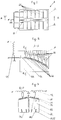
- Figure 1 describes the ultrasonic flaw probe/detector (1) which comprises two systems (2,3) of sub-panels (21,31), where each system constitutes a converter of ultrasonic vibrations.
- One system (2) constitutes a focusing ultrasonic radiator
- the second system (3) comprises a panel which receives the radiation from the first panel (2).
- the two systems must be separated from each other, for example, by means of an ultrasonic shutter (11).
- Each system of sub-plates (21,31) constitutes a series of straight, square or rectangular, surfaces, fixed to a single base (22,32) and shaped in the form of a cylindrical surface segment, wherein the sub-panels combine to form an active board (2 or 3) whose shape is close to the form of the base's cylindrical segment (22) (see Figure 2).
- the two bases (22, 32) onto which the piezoelectric panels are fixed (21, 31) are a transparent ultrasonic body, for example, a prism. The energy penetrates the product through one of the bases (22), and the energy reflected through the second base (32) reaches the panel of sub-plates (32) which comprise the receiver component (3).
- the base (22,32) is a central part of the acoustic focusing system which is intended to focus the ultrasonic energy in a certain direction or toward a certain point.
- the contact surface of the panel (21, 31) bases (22, 32), i.e., the prisms, are made of plastic material in most versions, and its drawback is significant abrasion wear.
- the bottom surface of the two bases (22,32) is fortified by the creation of grooves (24, 34), which are filled with layers (25, 35) of another material.
- These layers (25, 35) are made of any wear-resistant material - for example, tin, brass, plastic, - transparent to ultrasonic radiation, wherein the thickness of the layer is smaller than the wavelength of the ultrasonic radiation in the bases (22, 32).
- the sub-plates (21,31) are made of a piezoelectric material and their attachment to the base (22,32) in the above mentioned geometric form, endows the panel (2, 3) which the required ability to focus the rays.
- Each piezoelectric sub-plate is coated on both sides (41, 42) with a conductive cover casing intended to include it within the electrical circuit (4) (see Figure 6).
- the sub-plates are attached by bonding to a base (22, 32) with geometrically-shaped edges.
- the parameters and the properties of the sub-plate (21, 31) system (2, 3), are adjusted by electronic means (44, 45), so that each point on the panel (2, 3) is endowed with equal or variable parameters according to the requirements of the specific test.
- Each panel (2, 3) is connected to the electricity network by means of its own transformer (45), for example, an auto-transformer, as the upper coating (41) of each piezoelectric sub-plate (21, 31), is electrically connected by adjustable electronic means (44), for example by means of variable resistance to the mid-point of the transformer itself (45).
- transformer reduces the effect of the static capacitance of the sub-plate system (2 or 3) to input parameters, and thus increases the sensitivity of the ultrasonic flaw detector (1) to a great extent.
- variable resistors (44) connect and adjust each sub-plate (21, 31) separately.
- the sub-plates (21, 31) can be interconnected through coordinating and adjustable resistors (44) in parallel, in sequence or in groups, where the sub-plates in each group are interconnected in sequence and the groups are connected in parallel. Adjustment of the sub-plate (21, 31) parameters is carried out by electronic means, as shown in Figure 2.
- the number of sub-plates (21, 31) is usually far greater than two, but even only two sub-plates permit improve the characteristics and properties of each of the systems (2, 3).
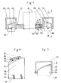
- Figure 4 describes an ultrasonic flaw probe/detector (1) in which the two converters are separated from each other, and each of them is placed within its own cover (23, 33), and they are connected into a single unit (1) by means of a holder (5).
- the radiating component (2) and the radiation receiving component (3) are connected to the holder (5) by means of bridges (6, 7).
- the connection between one of the converters, for example the radiator (2), and the holder (5) is established by means of a fixed bridge (6), while the connection between the other converter, for example the receiver (3), and the holder (5) is established by a bridge (7) with a hinge (71).
- the hinge (71) facilitates the performance of more accurate tests on angular and non-uniform surfaces.
- the hinge (71) is comprised of two cylinders (72, 73) of different diameters, an external hollow cylinder (72) and an internal solid one (73).
- a small gap is left between the two cylinders, which allows one cylinder (73) to turn within the other (72), wherein this movement is limited by special means, for example a rod (74) connected to one of the cylinders, for example the inner one (73), and moves within the slot of the second cylinder, for example (72), in order to restrict its movements within the limits required for the performance of the tests.
- One version comprises two hinges within every one of the bridges (7, 6) which allow a limited circular movement at an incline of about 10° relative to the vertical position of each of the separate converters (2, 3).
- the connection of the bridges (6, 7) to the bases (22, 32) is carried out through the covers (23, 33) of the radiator and the receiver (2, 3), so that the limited circular movement is of the converter covers (2, 3).
- Adjusting means allow for the control of the radiator and receiver (2, 3) positions to the type and conditions of a specific test.
- the connection between the bases (22, 32) and the covers (23, 33) of the radiator and the receiver (2, 3) is carried out through adjusting means (34) which enable a preferred position of the bases (22, 32) relative to the covers (23, 33).
- the tester presses the holder (5) and thus also presses the converters (2, 3) and each one of them receives the most appropriate angle for the surface component beneath it. Afterward, the device is slid over the product being tested, during which the device radiates ultrasonic rays and receives them.
Landscapes
- Engineering & Computer Science (AREA)
- Mechanical Engineering (AREA)
- Physics & Mathematics (AREA)
- Health & Medical Sciences (AREA)
- Life Sciences & Earth Sciences (AREA)
- Chemical & Material Sciences (AREA)
- Analytical Chemistry (AREA)
- Biochemistry (AREA)
- General Health & Medical Sciences (AREA)
- General Physics & Mathematics (AREA)
- Immunology (AREA)
- Pathology (AREA)
- Investigating Or Analyzing Materials By The Use Of Ultrasonic Waves (AREA)
Applications Claiming Priority (2)
| Application Number | Priority Date | Filing Date | Title |
|---|---|---|---|
| IL105085A IL105085A0 (en) | 1993-03-17 | 1993-03-17 | Method and device for revealing defects in materials and their connections |
| IL10508593 | 1993-03-17 |
Publications (1)
| Publication Number | Publication Date |
|---|---|
| EP0620434A1 true EP0620434A1 (fr) | 1994-10-19 |
Family
ID=11064628
Family Applications (1)
| Application Number | Title | Priority Date | Filing Date |
|---|---|---|---|
| EP93310045A Withdrawn EP0620434A1 (fr) | 1993-03-17 | 1993-12-14 | Sonde ultrasonore |
Country Status (3)
| Country | Link |
|---|---|
| US (1) | US5551296A (fr) |
| EP (1) | EP0620434A1 (fr) |
| IL (1) | IL105085A0 (fr) |
Cited By (1)
| Publication number | Priority date | Publication date | Assignee | Title |
|---|---|---|---|---|
| DE19642072A1 (de) * | 1995-11-27 | 1997-05-28 | Mitsubishi Electric Corp | Zusammengesetzte Sondenvorrichtung |
Families Citing this family (1)
| Publication number | Priority date | Publication date | Assignee | Title |
|---|---|---|---|---|
| US6520018B1 (en) * | 2000-11-17 | 2003-02-18 | Enertec Mexico, S.R.L. De C.V. | Ultrasonic inspection method for lead-acid battery terminal posts |
Citations (4)
| Publication number | Priority date | Publication date | Assignee | Title |
|---|---|---|---|---|
| US4170142A (en) * | 1977-07-15 | 1979-10-09 | Electric Power Research Institute, Inc. | Linear transducer array and method for both pulse-echo and holographic acoustic imaging |
| DE3540610A1 (de) * | 1985-11-15 | 1987-05-21 | Fraunhofer Ges Forschung | Ultraschallpruefkopf |
| EP0379229A2 (fr) * | 1985-05-20 | 1990-07-25 | Matsushita Electric Industrial Co., Ltd. | Sonde ultrasonore |
| EP0404154A2 (fr) * | 1989-06-22 | 1990-12-27 | Terumo Kabushiki Kaisha | Sonde à ultrasons avec couche de matériaux à épaisseur irrégulière |
Family Cites Families (6)
| Publication number | Priority date | Publication date | Assignee | Title |
|---|---|---|---|---|
| US2700895A (en) * | 1949-04-06 | 1955-02-01 | Babcock & Wilcox Co | Apparatus for ultrasonic examination of bodies |
| FR2349139A1 (fr) * | 1975-11-20 | 1977-11-18 | Centre Techn Ind Mecanique | Procede et dispositif d'examen non destructif par ultrasons |
| JPS63207300A (ja) * | 1987-02-24 | 1988-08-26 | Toshiba Corp | 超音波プロ−ブ |
| US4995260A (en) * | 1989-07-14 | 1991-02-26 | The United States Of America As Represented By The United States Department Of Energy | Nondestructive material characterization |
| JP2789234B2 (ja) * | 1989-10-02 | 1998-08-20 | 株式会社日立メディコ | 超音波診断装置 |
| US5349860A (en) * | 1989-11-28 | 1994-09-27 | Nkk Corporation | Apparatus for measuring the thickness of clad material |
-
1993
- 1993-03-17 IL IL105085A patent/IL105085A0/xx unknown
- 1993-12-14 EP EP93310045A patent/EP0620434A1/fr not_active Withdrawn
-
1995
- 1995-08-28 US US08/520,174 patent/US5551296A/en not_active Expired - Fee Related
Patent Citations (4)
| Publication number | Priority date | Publication date | Assignee | Title |
|---|---|---|---|---|
| US4170142A (en) * | 1977-07-15 | 1979-10-09 | Electric Power Research Institute, Inc. | Linear transducer array and method for both pulse-echo and holographic acoustic imaging |
| EP0379229A2 (fr) * | 1985-05-20 | 1990-07-25 | Matsushita Electric Industrial Co., Ltd. | Sonde ultrasonore |
| DE3540610A1 (de) * | 1985-11-15 | 1987-05-21 | Fraunhofer Ges Forschung | Ultraschallpruefkopf |
| EP0404154A2 (fr) * | 1989-06-22 | 1990-12-27 | Terumo Kabushiki Kaisha | Sonde à ultrasons avec couche de matériaux à épaisseur irrégulière |
Cited By (4)
| Publication number | Priority date | Publication date | Assignee | Title |
|---|---|---|---|---|
| DE19642072A1 (de) * | 1995-11-27 | 1997-05-28 | Mitsubishi Electric Corp | Zusammengesetzte Sondenvorrichtung |
| FR2741717A1 (fr) * | 1995-11-27 | 1997-05-30 | Mitsubishi Electric Corp | Appareil a sonde composite |
| DE19642072C2 (de) * | 1995-11-27 | 1999-04-22 | Mitsubishi Electric Corp | Zusammengesetzte Sondenvorrichtung |
| US5974890A (en) * | 1995-11-27 | 1999-11-02 | Mitsubishi Denki Kabushiki Kaisha | Composite probe apparatus |
Also Published As
| Publication number | Publication date |
|---|---|
| US5551296A (en) | 1996-09-03 |
| IL105085A0 (en) | 1993-08-18 |
Similar Documents
| Publication | Publication Date | Title |
|---|---|---|
| US20070000328A1 (en) | Ultrasonic method for the accurate measurement of crack height in dissimilar metal welds using phased array | |
| JPH06502250A (ja) | 管の外径を測定する超音波方法及び装置 | |
| US3021706A (en) | Ultrasonic materials testing system | |
| US3233449A (en) | Method and apparatus for ultrasonic testing of pipe | |
| GB2317700A (en) | Apparatus for measuring the quality of spot welds | |
| EP0186014A2 (fr) | Appareil pour placer de façon ajustable des dispositifs de test par ondes ultrasonores | |
| Luker et al. | Phase calibration of hydrophones | |
| US3262307A (en) | Omnidirectional ultrasonic search system | |
| JPS59214793A (ja) | 燃料要素の欠陥の検出方法及び装置 | |
| US5551296A (en) | Method and device for revealing defects in materials and their connections | |
| CN207964729U (zh) | 超声相控阵小角度纵波对轴身进行探伤的装置 | |
| US3776026A (en) | Ultrasonic flaw determination by spectral anaylsis | |
| CN110376286B (zh) | 一种在役盆式绝缘子智能自动化超声检测系统和方法 | |
| US3940952A (en) | Detecting abnormality | |
| KR20150131289A (ko) | 미지의 표면 기하구조를 갖는 부품의 초음파 검사 | |
| US3140600A (en) | Liquid immersion ultrasonic apparatus and method for the non-destructive testing of solid bodies | |
| EP0367462A1 (fr) | Mesure de la fuite d'une onde électromagnétique | |
| EP0198867A1 (fr) | Inspection electromagnetique | |
| Krautkrämer et al. | The pulse-echo method; Design and performance of a pulse-echo flaw detector | |
| Uchida et al. | Availability study of a phased array ultrasonic technique | |
| Hanstock et al. | Ultrasonic inspection of tubes | |
| Becker et al. | NONDESTRUCTIVE EVALUATION OF CLADDING COLD WORK AND GRAIN SIZE. | |
| Blitz et al. | Eddy-current surface-crack sizing in steel with high lift-off | |
| SU926585A1 (ru) | Имитатор дл настройки дефектоскопов | |
| SU1677622A1 (ru) | Ультразвуковой пьезоэлектрический преобразователь |
Legal Events
| Date | Code | Title | Description |
|---|---|---|---|
| PUAI | Public reference made under article 153(3) epc to a published international application that has entered the european phase |
Free format text: ORIGINAL CODE: 0009012 |
|
| AK | Designated contracting states |
Kind code of ref document: A1 Designated state(s): DE FR GB NL |
|
| 17P | Request for examination filed |
Effective date: 19950327 |
|
| STAA | Information on the status of an ep patent application or granted ep patent |
Free format text: STATUS: THE APPLICATION IS DEEMED TO BE WITHDRAWN |
|
| 18D | Application deemed to be withdrawn |
Effective date: 19960701 |