EP0620466A1 - Dispositif pour produire la rotation coordinée de eux composants liés - Google Patents
Dispositif pour produire la rotation coordinée de eux composants liés Download PDFInfo
- Publication number
- EP0620466A1 EP0620466A1 EP94105583A EP94105583A EP0620466A1 EP 0620466 A1 EP0620466 A1 EP 0620466A1 EP 94105583 A EP94105583 A EP 94105583A EP 94105583 A EP94105583 A EP 94105583A EP 0620466 A1 EP0620466 A1 EP 0620466A1
- Authority
- EP
- European Patent Office
- Prior art keywords
- cam segment
- cam
- components
- opening
- shafts
- Prior art date
- Legal status (The legal status is an assumption and is not a legal conclusion. Google has not performed a legal analysis and makes no representation as to the accuracy of the status listed.)
- Granted
Links
- 230000003287 optical effect Effects 0.000 claims description 12
- 230000002093 peripheral effect Effects 0.000 claims description 2
- 238000004804 winding Methods 0.000 description 3
- 230000007246 mechanism Effects 0.000 description 2
- 239000004593 Epoxy Substances 0.000 description 1
- 238000004873 anchoring Methods 0.000 description 1
- 230000007812 deficiency Effects 0.000 description 1
- 238000001356 surgical procedure Methods 0.000 description 1
Images

Classifications
-
- F—MECHANICAL ENGINEERING; LIGHTING; HEATING; WEAPONS; BLASTING
- F16—ENGINEERING ELEMENTS AND UNITS; GENERAL MEASURES FOR PRODUCING AND MAINTAINING EFFECTIVE FUNCTIONING OF MACHINES OR INSTALLATIONS; THERMAL INSULATION IN GENERAL
- F16C—SHAFTS; FLEXIBLE SHAFTS; ELEMENTS OR CRANKSHAFT MECHANISMS; ROTARY BODIES OTHER THAN GEARING ELEMENTS; BEARINGS
- F16C11/00—Pivots; Pivotal connections
- F16C11/04—Pivotal connections
- F16C11/12—Pivotal connections incorporating flexible connections, e.g. leaf springs
-
- G—PHYSICS
- G02—OPTICS
- G02B—OPTICAL ELEMENTS, SYSTEMS OR APPARATUS
- G02B7/00—Mountings, adjusting means, or light-tight connections, for optical elements
- G02B7/02—Mountings, adjusting means, or light-tight connections, for optical elements for lenses
- G02B7/12—Adjusting pupillary distance of binocular pairs
Definitions
- the present invention generally relates to an apparatus for providing the coordinated rotation of two interrelated components and, in particular, relates to one such apparatus having first and second cam segment lobes each respectively associated with first and second devices and including means for urging the first and second cam segment lobes into rotatable contact with each other.
- interocular distance adjustment mechanisms include such arrangements as interocular gear systems and fork and pin drives.
- gear systems are expensive and can be quite complex if little of no play is acceptable.
- the movement is usually ergonomically rough due, primarily, to the high frictional load placed on the bearings of such a system.
- Typical fork and pin drive mechanisms not only exhibit noticeable play but also a changing rate of interocular rotation along with excessive friction at the pin/fork interface.
- interocular gear system and the pin and drive arrangements are acceptable in many applications they are frequently unacceptable in applications where precise, smooth, play-free adjustment of the interocular distance of two eyepieces is required.
- interocular gear systems or fork and pin drives is, for the deficiencies cited above, quite unacceptable to the user.
- This object is accomplished, at least in part by an apparatus having first and second components having first and second cam segment lobes respectively associated therewith and means for urging the first and second cam segment lobes in rotatable contact with each other.
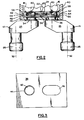
- An apparatus for providing the coordinated rotation of two interrelated components, 12 and 14 , respectively, includes first and second cam segments, 16 and 18 , respectively, each having a cam segment lobe, 20 and 22 , respectively, associated therewith, and means 24 for urging the cam segment lobes, 20 and 22 , into contact with each other such that when a torque is applied to either one of both of the components, 12 and 14 , the lateral distance between the components, 12 and 14 , is changed.
- the apparatus 10 is an optical apparatus wherein the first and second components, 12 and 14 , respectively, are eyepieces.
- Each eyepiece includes a body 25 having a viewing end 26 and a light receiving end 28 .
- the eyepieces include a plurality of optical elements, not shown in the drawings, for directing light received at the light receiving end 28 to the viewing end 26 . Consequently, the light receiving end 28 has an optical axis 30 associated therewith and the viewing end 26 has an optical axis 32 associated therewith.
- the optical axis 30 the light viewing end 28 of each component 12 and 14 is substantially parallel with and offset from the optical axis 32 of the viewing end 26 .
- each of the components, 12 and 14 includes a cylindrical shaft, 34 and 36 , respectively, extending from the body 25 at the light receiving end 28 thereof.
- the shafts, 34 and 36 extend through a wall 38 of a housing 40 .
- one of the shafts, for example, shaft 34 is fixedly mounted through a first opening 42 , as shown in Figure 3, in the wall 38 by means of a bearing 44 that allows only rotational movement of the shaft 34 .
- the other shaft 36 extends through an elongated opening 46 , as shown in Figure 3, through the wall 38 that allows both rotational movement of the shaft 36 as well as movement lateral with respect to the shaft 34 .
- the eyepieces are secured to the housing 40 by securing the first and second cam segments, 16 and 18 , respectively, to the first and second shafts, 34 and 36 , respectively, on the side 48 of the wall 38 opposite the respective viewing ends 26 .
- each cam segment, 16 and 18 includes a shaft opening 50 sized to receive therethrough one of the shafts, 34 or 36 .
- Each cam segment, 16 and 18 also includes one of the cam segment lobes, 20 and 22 , respectively.
- each cam segment lobe, 20 and 22 defines an arc segment of a circle that is concentric with the shaft opening 50 of the respective cam segments, 16 and 18 .
- each of the cam segment lobes, 20 and 22 subtend between 20 degrees and 50 degrees of arc.
- each cam segment, 16 and 18 is provided with at least one slot 52 extending into the cam segment, 16 and 18 , from the periphery of the shaft opening 50 .
- Each shaft, 34 and 36 is provided with keys 54 sized to extend into the corresponding slots 52 .
- the keys 54 and slots 52 are disposed such that when the cam segments, 16 and 18 , are fitted onto the shafts, 34 and 36 , respectively, the first and second cam segment lobes, 20 and 22 , respectively, face each other.
- the keys 54 and slots 52 are disposed so that the point of contact of the cam segment lobes, 20 and 22 , lies along a line connecting the optical axes 30 of the light receiving ends 28 of the components, 12 and 14 .
- the cam segments, 16 and 18 can be secured to the cylindrical shafts, 34 and 36 , respectively, by any means known in the art, including frictional fitting, epoxying, or the like.
- each cam segment, 16 and 18 includes a peripheral groove 56 that is concentric with the shaft opening 50 such that a substantial amount of each cam segment lobe, 20 and 22 , is grooved.
- the periphery 58 of each cam segment, 16 and 18 is machined to provide an anchor pin 60 .
- the anchor pins 60 are formed distal each other.
- the means 24 for urging the cam segment lobes, 20 and 22 , into contact with each other includes a preloaded spring wire that is wrapped around the cam segments, 16 and 18 , in the grooves 56 thereof. It has been found that one and a half figure eight windings work quite effectively although other winding configurations can also be implemented.
- the spring wire is wrapped around the anchor pins 60 to secure the wire in place and to maintain the tension thereon.
- epoxy 64 can be applied to the disc portions 62 of the cam segments, 16 and 18 , subsequent to the winding and anchoring of the wire.
- the grooves 56 are about 0.028 inches wide and the spring wire is 0.008 inches in diameter.
- the diameter of the first opening 42 , the width of the elongated opening 46 and the outside diameter of the cylindrical shafts, 34 and 36 are cooperatively sized so that the cylindrical shaft 36 moves smoothly in a lateral direction within the elongated opening 46 .
- the spring wire is wound about the shafts, 34 and 36 , to a tightness that allows both smooth movement and play-free adjustment.
- the apparatus 10 provides smooth, play-free and relatively inexpensive coordinated rotation between the component, 12 and 14 .
Landscapes
- Physics & Mathematics (AREA)
- Engineering & Computer Science (AREA)
- General Engineering & Computer Science (AREA)
- General Physics & Mathematics (AREA)
- Optics & Photonics (AREA)
- Mechanical Engineering (AREA)
- Telescopes (AREA)
- Superconductive Dynamoelectric Machines (AREA)
- Microscoopes, Condenser (AREA)
Applications Claiming Priority (2)
| Application Number | Priority Date | Filing Date | Title |
|---|---|---|---|
| US46055 | 1993-04-12 | ||
| US08/046,055 US5410436A (en) | 1993-04-12 | 1993-04-12 | Apparatus for providing the coordinated rotation of two interrelated optical components |
Publications (2)
| Publication Number | Publication Date |
|---|---|
| EP0620466A1 true EP0620466A1 (fr) | 1994-10-19 |
| EP0620466B1 EP0620466B1 (fr) | 1997-06-18 |
Family
ID=21941339
Family Applications (1)
| Application Number | Title | Priority Date | Filing Date |
|---|---|---|---|
| EP94105583A Expired - Lifetime EP0620466B1 (fr) | 1993-04-12 | 1994-04-11 | Dispositif pour produire la rotation coordinée de eux composants liés |
Country Status (7)
| Country | Link |
|---|---|
| US (1) | US5410436A (fr) |
| EP (1) | EP0620466B1 (fr) |
| JP (1) | JP2780923B2 (fr) |
| KR (1) | KR0167374B1 (fr) |
| CA (1) | CA2121080C (fr) |
| DE (1) | DE69403847T2 (fr) |
| IL (1) | IL109288A (fr) |
Cited By (1)
| Publication number | Priority date | Publication date | Assignee | Title |
|---|---|---|---|---|
| FR2997388A1 (fr) * | 2012-10-26 | 2014-05-02 | Thales Sa | Systeme de motorisation a couple adapte pour articulation a moyens d'enroulement croises |
Families Citing this family (3)
| Publication number | Priority date | Publication date | Assignee | Title |
|---|---|---|---|---|
| US5867313A (en) * | 1995-07-31 | 1999-02-02 | Itt Corporation | Multipurpose night vision monocular |
| JPH1039190A (ja) * | 1996-07-19 | 1998-02-13 | Olympus Optical Co Ltd | カメラの駆動装置 |
| JP7158893B2 (ja) * | 2018-05-18 | 2022-10-24 | キヤノン株式会社 | 光学機器 |
Citations (4)
| Publication number | Priority date | Publication date | Assignee | Title |
|---|---|---|---|---|
| US1965755A (en) * | 1932-10-17 | 1934-07-10 | Bell & Howell Co | Binocular |
| GB622466A (en) * | 1945-03-14 | 1949-05-03 | Pierre Sordoiliet | Improvements in or relating to binoculars |
| US4272153A (en) * | 1978-07-31 | 1981-06-09 | Beecher William J | Binocular with novel arrangement of hinge means between the telescopes thereof |
| JPS61116311A (ja) * | 1984-11-12 | 1986-06-03 | Canon Inc | 基線長変更装置 |
Family Cites Families (5)
| Publication number | Priority date | Publication date | Assignee | Title |
|---|---|---|---|---|
| US956182A (en) * | 1909-08-25 | 1910-04-26 | Zeiss Carl Fa | Double telescope. |
| US4545656A (en) * | 1983-09-16 | 1985-10-08 | Toei Optical Industries Co. Ltd. | Focus adjusting device for binocular |
| JPS60169612U (ja) * | 1984-04-20 | 1985-11-11 | 鎌倉光機株式会社 | 双眼鏡のズ−ム連動機構 |
| JPH0516571Y2 (fr) * | 1988-04-30 | 1993-04-30 | ||
| NL8900345A (nl) * | 1989-02-13 | 1990-09-03 | Hemmer Trading Bv | Instelbare gezichtshulp. |
-
1993
- 1993-04-12 US US08/046,055 patent/US5410436A/en not_active Expired - Fee Related
-
1994
- 1994-04-11 IL IL10928894A patent/IL109288A/en not_active IP Right Cessation
- 1994-04-11 EP EP94105583A patent/EP0620466B1/fr not_active Expired - Lifetime
- 1994-04-11 DE DE69403847T patent/DE69403847T2/de not_active Expired - Fee Related
- 1994-04-12 JP JP6073654A patent/JP2780923B2/ja not_active Expired - Lifetime
- 1994-04-12 KR KR1019940007579A patent/KR0167374B1/ko not_active Expired - Fee Related
- 1994-04-12 CA CA002121080A patent/CA2121080C/fr not_active Expired - Fee Related
Patent Citations (4)
| Publication number | Priority date | Publication date | Assignee | Title |
|---|---|---|---|---|
| US1965755A (en) * | 1932-10-17 | 1934-07-10 | Bell & Howell Co | Binocular |
| GB622466A (en) * | 1945-03-14 | 1949-05-03 | Pierre Sordoiliet | Improvements in or relating to binoculars |
| US4272153A (en) * | 1978-07-31 | 1981-06-09 | Beecher William J | Binocular with novel arrangement of hinge means between the telescopes thereof |
| JPS61116311A (ja) * | 1984-11-12 | 1986-06-03 | Canon Inc | 基線長変更装置 |
Non-Patent Citations (1)
| Title |
|---|
| PATENT ABSTRACTS OF JAPAN vol. 10, no. 300 (P - 506)<2356> 14 October 1986 (1986-10-14) * |
Cited By (3)
| Publication number | Priority date | Publication date | Assignee | Title |
|---|---|---|---|---|
| FR2997388A1 (fr) * | 2012-10-26 | 2014-05-02 | Thales Sa | Systeme de motorisation a couple adapte pour articulation a moyens d'enroulement croises |
| US9242744B2 (en) | 2012-10-26 | 2016-01-26 | Thales | Motorization system with torque suitable for hinge with crossed winding means |
| EP2724943A3 (fr) * | 2012-10-26 | 2018-01-10 | Thales | Système de motorisation à couple adapté pour articulation à moyens d'enroulement croisés |
Also Published As
| Publication number | Publication date |
|---|---|
| DE69403847D1 (de) | 1997-07-24 |
| KR0167374B1 (ko) | 1999-04-15 |
| DE69403847T2 (de) | 1998-01-08 |
| CA2121080A1 (fr) | 1994-10-13 |
| EP0620466B1 (fr) | 1997-06-18 |
| CA2121080C (fr) | 1999-09-21 |
| IL109288A (en) | 1996-12-05 |
| JP2780923B2 (ja) | 1998-07-30 |
| IL109288A0 (en) | 1994-07-31 |
| JPH0749455A (ja) | 1995-02-21 |
| US5410436A (en) | 1995-04-25 |
Similar Documents
| Publication | Publication Date | Title |
|---|---|---|
| US5231473A (en) | Lens barrel | |
| US5377048A (en) | Lens barrel | |
| US6644862B1 (en) | Optical mount | |
| US4650296A (en) | Magnification changing mechanism of a microscope | |
| US4304463A (en) | Lens barrel automatic focalization device | |
| US5410436A (en) | Apparatus for providing the coordinated rotation of two interrelated optical components | |
| US4507979A (en) | Arrangement for rotating the shaft of an electrical component | |
| JP3006063B2 (ja) | 顕微鏡用鏡筒 | |
| US6094534A (en) | Lens barrel of camera | |
| US5146260A (en) | Lens barrel | |
| JP2864193B2 (ja) | レンズ鏡筒 | |
| US4605288A (en) | Zoom interlocking mechanism for binocular | |
| US5654823A (en) | Microscope | |
| JP2787244B2 (ja) | 二軸レンズ駆動装置 | |
| JPH0599211A (ja) | 軸固定機構 | |
| US5563735A (en) | Parallel action angular adjustment mechanism | |
| JPS6355683B2 (fr) | ||
| JP2920592B2 (ja) | 照準望遠鏡 | |
| JPH10170806A (ja) | レンズ鏡筒 | |
| JPH05119248A (ja) | ズームレンズ駆動装置 | |
| JPS6236617A (ja) | レンズ繰り出し装置 | |
| JPS61175605A (ja) | レンズ鏡筒の合焦装置 | |
| JPS5961803A (ja) | レンズ鏡胴 | |
| JPH0990191A (ja) | 駆動装置およびそれを用いた光学機器 | |
| JP3359147B2 (ja) | レンズ装置 |
Legal Events
| Date | Code | Title | Description |
|---|---|---|---|
| PUAI | Public reference made under article 153(3) epc to a published international application that has entered the european phase |
Free format text: ORIGINAL CODE: 0009012 |
|
| AK | Designated contracting states |
Kind code of ref document: A1 Designated state(s): DE FR GB |
|
| 17P | Request for examination filed |
Effective date: 19950418 |
|
| 17Q | First examination report despatched |
Effective date: 19950711 |
|
| GRAG | Despatch of communication of intention to grant |
Free format text: ORIGINAL CODE: EPIDOS AGRA |
|
| GRAH | Despatch of communication of intention to grant a patent |
Free format text: ORIGINAL CODE: EPIDOS IGRA |
|
| GRAH | Despatch of communication of intention to grant a patent |
Free format text: ORIGINAL CODE: EPIDOS IGRA |
|
| GRAA | (expected) grant |
Free format text: ORIGINAL CODE: 0009210 |
|
| AK | Designated contracting states |
Kind code of ref document: B1 Designated state(s): DE FR GB |
|
| REF | Corresponds to: |
Ref document number: 69403847 Country of ref document: DE Date of ref document: 19970724 |
|
| ET | Fr: translation filed | ||
| PLBE | No opposition filed within time limit |
Free format text: ORIGINAL CODE: 0009261 |
|
| STAA | Information on the status of an ep patent application or granted ep patent |
Free format text: STATUS: NO OPPOSITION FILED WITHIN TIME LIMIT |
|
| 26N | No opposition filed | ||
| REG | Reference to a national code |
Ref country code: GB Ref legal event code: 732E |
|
| REG | Reference to a national code |
Ref country code: FR Ref legal event code: TP Ref country code: FR Ref legal event code: CD Ref country code: FR Ref legal event code: CA |
|
| REG | Reference to a national code |
Ref country code: GB Ref legal event code: IF02 |
|
| PGFP | Annual fee paid to national office [announced via postgrant information from national office to epo] |
Ref country code: FR Payment date: 20020311 Year of fee payment: 9 |
|
| PGFP | Annual fee paid to national office [announced via postgrant information from national office to epo] |
Ref country code: GB Payment date: 20020313 Year of fee payment: 9 |
|
| PGFP | Annual fee paid to national office [announced via postgrant information from national office to epo] |
Ref country code: DE Payment date: 20020315 Year of fee payment: 9 |
|
| PG25 | Lapsed in a contracting state [announced via postgrant information from national office to epo] |
Ref country code: GB Free format text: LAPSE BECAUSE OF NON-PAYMENT OF DUE FEES Effective date: 20030411 |
|
| PG25 | Lapsed in a contracting state [announced via postgrant information from national office to epo] |
Ref country code: DE Free format text: LAPSE BECAUSE OF NON-PAYMENT OF DUE FEES Effective date: 20031101 |
|
| GBPC | Gb: european patent ceased through non-payment of renewal fee |
Effective date: 20030411 |
|
| PG25 | Lapsed in a contracting state [announced via postgrant information from national office to epo] |
Ref country code: FR Free format text: LAPSE BECAUSE OF NON-PAYMENT OF DUE FEES Effective date: 20031231 |
|
| REG | Reference to a national code |
Ref country code: FR Ref legal event code: ST |