EP0620568A2 - Rotierende elektronische Vorrichtung - Google Patents
Rotierende elektronische Vorrichtung Download PDFInfo
- Publication number
- EP0620568A2 EP0620568A2 EP94105628A EP94105628A EP0620568A2 EP 0620568 A2 EP0620568 A2 EP 0620568A2 EP 94105628 A EP94105628 A EP 94105628A EP 94105628 A EP94105628 A EP 94105628A EP 0620568 A2 EP0620568 A2 EP 0620568A2
- Authority
- EP
- European Patent Office
- Prior art keywords
- rotary
- operation shaft
- circular
- rotary operation
- hole
- Prior art date
- Legal status (The legal status is an assumption and is not a legal conclusion. Google has not performed a legal analysis and makes no representation as to the accuracy of the status listed.)
- Granted
Links
Images






Classifications
-
- H—ELECTRICITY
- H01—ELECTRIC ELEMENTS
- H01C—RESISTORS
- H01C10/00—Adjustable resistors
- H01C10/10—Adjustable resistors adjustable by mechanical pressure or force
Definitions
- the present invention relates to a rotary electronic device which is suitable, for instance for use in a zooming speed controlling unit of a video camera.
- a zooming speed controlling unit of a video camera is provided for zooming out on the "TELE (telescopic)" side and zooming in on “WIDE (wide range)” side, and required to instantaneously stop the movement of a lens unit of the video camera at a predetermined position, a seesaw manipulation-type switch of a neutral position return-motion is widely used in an operation unit for the zooming speed controlling unit.
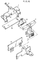
- FIG.15 is an exploded perspective view showing the seesaw manipulation-type switch of the conventional seesaw manipulation-type electronic device.
- FIG.16 is a front view showing a base plate of the conventional seesaw manipulation-type electronic device.
- FIG.17 is a front view of the base plate of FIG.16.
- FIG.18 is a front view explaining an operation of a return mechanism of the conventional seesaw manipulation-type electronic device.
- a manipulation key 3 of the seesaw manipulation-type switch is swayably provided to a support shaft 2 in an upper portion of a housing 1.
- a brush receiving plate 3a is extendedly provided to be arranged perpendicularly to the support shaft 2, and an electrically-conductive brush 4 is fixed to the brush-receiving plate 3a in a cantilever-fashion.
- the base plate 6 has a plurality of sector-shaped fixed contacts 5a, 5b, 5c, 5d, 5e, 5f, 5g, 5h, 5i and 5j formed to have a concentric pattern.
- the base plate 6 is disposed to face one face of the brush-receiving plate 3a in the housing 1, and the brush 4 is arranged to elastically contact a surface of the sector-shaped fixed contacts 5a --- 5j on the base plate 6.
- a pair of spring receiving members 7, 8 is rotatably attached by the support shaft 2.
- a coil spring 9 is compressively provided between both the spring receiving members 7 and 8.
- a stopping protrusion 1a protruding from a side wall of the housing 1 and an engaging pin 3b protruding from the brush-receiving plate 3a are inserted and interposed between both the spring receiving members 7 and 8 as shown in FIG.18.
- the seesaw manipulation-type switch has a bottom plate 10 and a side plate 11 facing to the base plate 6.
- the manipulation key 3 and the brush-receiving plate 3a are integrally rotated around the support shaft 2 as a rotation axis. And the brush 4 turns and slides on a surface of the base plate 6, thereby a position of contact point in the sector-shaped fixed contacts 5a --- 5j (FIG.16) is changed.
- the brush 4 contacts with a particular contact in the plurality of the sector-shaped fixed contacts 5a --- 5j to turn on a circuit connected to the particular contact, or departs from a particular contact in the sector-shaped fixed contacts 5a --- 5j to turn off a circuit connected to the particular contact, corresponding to a depressed stroke of the manipulation key 3.
- the engaging pin 3b turns one of the spring-receiving members 7, 8 against elasticity of the coil spring 9 as shown in FIG.18.
- the spring-receiving member 7 or 8 is returned to its initial neutral position by the elasticity of the coil spring 9, at the same time, the manipulation key 3 and the brush 4 return to the neutral position by contacting between the engaging pin 3b and the spring-receiving member 7 or 8.
- An object of the present invention is to provide a rotary electronic device, which has a neutral-position-returning mechanism, and which uses a torsion coil spring installed on a shaft of the neutral-position-returning mechanism without enlarging a whole of the electronic device.
- the present invention provides a rotary electronic device comprising: a holder having a circular through-hole; a rotary variable resistor having connection terminals and a rotary shaft, which is arranged concentrically with the circular through-hole, the rotary variable resistor being disposed at an end portion of the holder, a rotary operation shaft which is rotatably held by the circular through-hole, one end of which is coupled to the rotary shaft of the rotary variable resistor, and the other end of which is provided with stopping step portions for engaging with a protrusion of the holder.
- a rotary electronic device which has a small size and a low cost, can control an output value of it in a stepless mode.
- knob manipulation-type variable resistor of a first embodiment of a rotary electronic device in accordance with the present invention will be explained with reference to FIG.1 to FIG.5.
- FIG.1 is a sectional view showing the rotary-manipulation-type variable resistor of the first embodiment of the rotary electronic device in accordance with the present invention.
- FIG.2 is a perspective view of the rotary electronic device of FIG.1.
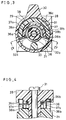
- FIG.3 is a sectional view taken along line III - III of FIG.1.
- FIG.4 is a partial sectional view taken along line IV - IV of FIG.3.
- FIG.5 is a sectional view showing a state that the knob manipulation-type variable resistor is operated by pushing a manipulation knob, starting from the state shown in FIG.3.
- a tubular holder 21 made by resin molding or metal die casting has a circular through-hole 22 in its center portion and a small hole 23 for fixing in its side portion.
- a rotary variable resistor 24 has a rotary shaft 25 in the center portion of the tubular holder 21, and connection terminals 26 on the rear face of the tubular holder 21.
- the rotary shaft 25 is so held by leg portions 27 at a rear end of the tubular holder 21 that it becomes concentric to the circular through-hole 22 of the tubular holder 21.
- a plurality of the connection terminals 26 protrude from the rear face of the knob manipulation-type variable resistor.
- a brush 24a contacts to a resistor 24b and slides on it by turning of the rotary shaft 25, thereby varying an output (resistance value) derived from the connection terminals 26.
- a rotary operation shaft 28 is comprised of a circular shaft 29 rotatably held by the circular through-hole 22 of the tubular holder 21 and a manipulation knob 30 radially extended from an end portion of the circular shaft 29.
- the other end 29a of the circular shaft 29 is coupled to the rotary shaft 25 of the rotary variable resistor 24, and a screw 31 inserted into a center hole 29b of the circular shaft 29 fixes both of the rotary shaft 25 and the circular shaft 29.
- stopping step portions 32a, 32b are provided at two lower positions of the manipulation knob 30 of the rotary operation shaft 28, and contact with a protrusion 33 of the tubular holder 21, so as to regulate a range of a turning angle of the rotary operation shaft 28.
- a torsion coil spring 36 is provided for keeping the rotary operation shaft 28 at a predetermined position, namely the manipulation knob 30 at a neutral position.
- a coil portion 36c of the torsion coil spring 36 is disposed on an outer periphery of the circular shaft 29 of the rotary operation shaft 28.
- Hook portions 36a, 36b (FIG.3) formed at both ends of the coil portion 36c are in contact with respective end faces 37a, 37b of step portion 37 provided near the stopping step portions 32a, 32b of the rotary operation shaft 28. And further the hook portions 36a, 36b are in contact with end faces 38a, 38b of protruding portion 38 arranged to pile the outside of the step portion 37 as shown in FIG.3.
- the hook portions 36a, 36b of the torsion coil spring 36 shown in FIG. 3 are in contact with these end faces 37a, 37b, 38a and 38b of the step portion 37 and the protruding portion 38 to apply a constant elasticity of the torsion coil spring 36.
- the facing angle between the end faces 38a, 38b of the protruding portions 38 of the tubular holder 21 are set at an large angle than the facing angle between the stopping step portions 32a and 32b of the rotary operation shaft 28.
- the end faces 37a, 37b of the step portion 37 of the rotary operation shaft 28 are so set that the center position of the step portion 37 conform with a center position between the stopping steps portions 32a and 32b.
- FIG.5 is a sectional view taken along line IV - IV of FIG.3, showing a state of the operation.
- the rotary shaft 25 coupled to the circular shaft 29 of the rotary variable resistor 24 is turned by the rotation of the rotary operation shaft 28, and thereby a resistance value derived from the connection terminals 26 is varied.
- the resistance value derived from the connection terminals 26 of the rotary variable resistor 24 is varied in a forward direction in a stepless mode in response to a turning angle of the rotary operation shaft 28, that is, an amount of pushing force applied to the manipulation knob 30.
- the rotary operation shaft 28 is returned to the initial position (shown in FIG.2), because the elasticity of the torsion coil spring 36 is applied to the rotary operation shaft 28 via the step portion 37 of the manipulation knob 30.
- the resistance value derived from the connection terminals 26 of the rotary variable resistor 24 can be varied in the reverse direction to the above-mentioned case of the pushing operation of the manipulation knob 30.
- knob-manipulation-type variable resistor of a second embodiment of a rotary electronic device in accordance with the present invention will be explained with reference to FIG.6 to FIG.9.
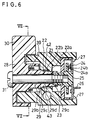
- FIG.6 is a sectional view showing the knob manipulation-type variable resistor of the second embodiment.
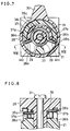
- FIG.7 is a sectional view taken along line VII - VII of FIG.6.
- FIG.8 is a partial sectional view of the rotary operation shaft portion of an essential part taken along line VIII - VIII of FIG.7.
- FIG.9 is a side sectional view showing a state that the knob manipulation-type variable resistor is operated by pushing a manipulation knob, starting from the state of FIG.7.
- Corresponding parts and components to the first embodiment are shown by the same numerals and marks, and the description thereon made in the first embodiment similarly apply. Differences and features of this second embodiment from the first embodiment are as follows.
- a tubular holder 21 made by resin molding or metal die casting has a circular through-hole 22 in its center portion and a fixing-use small hole 23 in its side portion. As shown in FIG.6, this circular through-hole 22 has a step, and a diameter of a right end portion 22a of the circular through-hole 22 is slightly smaller than a diameter of a left portion 22b.
- a rotary variable resistor 24 has a rotary shaft 25 in the center portion of the tubular holder 21, and connection terminals 26 on the rear face.
- the rotary shaft 25 is so held by leg portions 27 at an end of the tubular holder 21 that it becomes concentric to the circular through-hole 22 of the tubular holder 21.
- a plurality of the connection terminals 26 protrude from the rear face of the knob manipulation-type variable resistor.
- a brush 24a contacts to and slides on resistor 24b by turning said rotary shaft 25, and thereby an output (resistance value) derived from the connection terminal 26 is varied.
- a rotary operation shaft 28 comprises a circular shaft 29 rotatably held by the circular through-hole 22 of the tubular holder 21 and a manipulation knob 30, which is radially extended from an end portion of the circular shaft 29.
- the other end 29a of the circular shaft 29 is coupled to the rotary shaft 25 of the rotary variable resistor 24, and a screw 31 inserted into a center hole 29b of the circular shaft 29 fixes both of the rotary shaft 25 and the circular shaft 29.
- the cylindrical outer face of this circular shaft 29 has a step.
- a left end portion 29c of the circular shaft 29 has a larger diameter than a right portion 29d.
- the left end portion 29c of the circular shaft 29 is in contact with a large diameter portion, that is, left portion 22b of the circular through-hole 22.
- a right end portion 29a of circular shaft 29 is connected with a small diameter portion, that is, the right end portion 22a having a smaller inner diameter than that of the left portion 22b of the circular through-hole 22.
- a gap 42 is formed at an intermediate portion of the contacted portion, but both the right and left ends of the contact portion have almost no clearance and the circular shaft 29 are rotatably held by the circular through-hole 22.
- This gap 42 is filled with viscous grease 43 and serves as a grease reservoir, and thereby a damping function is provided to give some resistance force against rotation of the rotary operation shaft 28.
- the end faces 37a, 37b of the step portion 37 of the manipulation knob 30 of the rotary operation shaft 28 are in contact with a protrusion 33 of the tubular holder 21 via hook portions 39a, 39b, so as to regulate a range of a turning angle of the rotary operation shaft 28.
- These end faces 37a, 37b of the step portion 37 also serve as contact-use step portions of the hook portions 39a, 39b which is both ends of a torsion coil spring 39 for maintaining the rotary operation shaft 28, namely the manipulation knob 30 at a neutral position. That is, a coil portion 39c of the torsion coil spring 39 is disposed on a periphery of the circular shaft 29 of said rotary operation shaft 28.
- the hook portions 39a, 39b sheathed with soft elastic tubes 41a, 41b, for instance of neoplene tubes or rubber tubes etc. are in contact with the end faces 37a, 37b of the step portion 37 as stopper of the rotary operation shaft 28, and further hook portions 39a, 39b are in contact with the end faces 38a, 38b of the protruding portion 38 arranged on the outside of the step portion 37.
- the end faces 38a, 38b are arranged to have the same facing angle as the end faces 37a, 37b of the step portion 37.
- the hook portions 39a, 39b of the torsion coil spring 39 shown in FIG. 7 are in contact with these end faces 37a, 37b, 38a and 38b of the step portion 37 and the protruding portion 38 to apply a constant elasticity of the torsion coil spring 39 through the hook portions 39a, 39b.
- FIG. 9 is a sectional view showing a state of the operation state.
- the other end face 38b of the protruding portion 38 of the tubular holder 21 is in contact with the elastic tube 41b of the hook portion 39b, and therefore the torsion coil spring 39 is compressed against its elasticity by both the hook portions 39a and 39b of the torsion coil spring 39.
- the resistance value derived from the connection terminal 26 of the rotary variable resistor 24 varies in the predetermined direction in response to a turning angle of the rotary operation shaft 28, namely, an amount of pushing force applied to the manipulation knob 30.
- the end face 37a of the step portion 37 of the manipulation knob 30 presses the hook portion 39a of the torsion coil spring 39 to the protrusion 33 of the tubular holder 21. Since the hook portion 39a is sheathed with the elastic tube 41a, noise at the time of contact between the hook portion 39a and the step portion 37 is reduced.
- the rotary operation shaft 28 is returned to the initial neutral position (shown in FIG.7) and restored because the elasticity of the torsion coil spring 39 is applied to the rotary operation shaft 28 via the step portion 37 of the manipulation knob 30.
- the resistance value produced at the connection terminals 26 of the rotary variable resistor 24 can be varied in the reverse direction to the above-mentioned case.
- a modified embodiment may be such that a knob manipulation-type switch is constructed by changing the rotary variable resistor to a rotary change-over switch.
- the above-mentioned second embodiment has the following effects in addition to the aforementioned effects of the first embodiment shown in FIG.1 to FIG.5:
- FIG.10 to FIG.12 show a rotary variable resistor of the third embodiment of a rotary electronic device in accordance with the present invention.
- FIG.10 is a sectional view showing the rotary variable resistor of the third embodiment.
- FIG.11 is a sectional view taken along line XI - XI of FIG.10.
- FIG.12 is a sectional view showing a state that the rotary variable resistor is operated by turning a rotary manipulation shaft, starting from the state of FIG.11.
- Corresponding parts and components to the first embodiment are shown by the same numerals and marks, and the description thereon made in the first embodiment similarly apply. Differences and features of this third embodiment from the first embodiment are as follows.
- the rotary variable resistor can be converted into a knob manipulation-type variable resistor like the aforementioned first and second embodiments shown in FIG.1 to FIG.9, by attaching a knob 13A (shown with clain-line) to a rotary operation shaft 2A.
- a box-shape casing 1A made by resin molding or die casting has a circular through-hole 1Aa in its center portion.
- a rotary operation shaft 2A is rotatably held by the circular through-hole 1Aa of the box-shape casing 1A at a circular shaft portion 2Aa.
- two stopping protruding portions 12Aa, 12Ab of the rotary operation shaft 2A are provided to be respectively in contact with two stopping step portions 11Aa, 11Ab of the box-shape casing 1A so as to restrain a turning angle range of the rotary operation shaft 2A.
- a flexible protrusion 8A is provided so as to contact with stopping step portion 9Aa or 9Ab of the box-shape casing 1A immediately before contacting of the stopping protruding portion 12Aa or 12Ab with the stopping step portion 11Aa or 11Ab, when the rotary operation shaft 2A is turned as described later.
- Hook portions 3Ac, 3Ad at both ends of the coil portion 3Aa are in contact with protruding portions 12Ac, 12Ad of the rotary operation shaft 2A, respectively.
- the hook portions 3Ac, 3Ad are in contact with stopping step portions 11Ac, 11Ad of the box-shape casing 1A.
- the stopping step portions 11Ac, 11Ad are arranged at an outer position of the protruding portions 12Ac, 12Ad.
- the hook portions 3Ac, 3Ad are in contact with the stopping step portions 11Ac, 11Ad and the stopping protruding portions 12Ac, 12Ad to apply a constant elasticity of the torsion coil spring 3A.
- a base plate 5A is supported by a leg portion 1Ab of the box-shape casing 1A so that a circular through-hole 5Aa of the base plate 5A and the circular through-hole 1Aa of the box-shape casing 1A are concentric.
- the circular shaft portion 2Ab of the rotary operation shaft 2A is rotatably held by the circular through-hole 5Aa and the circular through-hole 1Aa.
- a plurality of terminals 6A which are protrusively provided on one side of the base plate 5A, are electrically connected to a circular resistance layer 7A on the base plate 5A.
- An output (resistance value) derived from the terminals 6A is varied by sliding a brush 4A on said circular resistance layer 7A.
- the brush 4A is fixed by a holding portion 2Ac on one face of an intermediate disk portion 2Ad of the rotary operation shaft 2A so as to rotate together with the holding portion 2Ac.
- FIG.12 is a sectional view showing an operation state.
- the flexible protrusion 8A of the rotary operation shaft 2A touches with the stopping step portion 9Aa of the box-shape casing 1A.
- the stopping protruding portion 12Ab of the rotary operation shaft 2A and the stopping step portion 11Ab of the box-shape casing 1A do not contact with each other, and disposed to have a gap ⁇ as shown in FIG.12.
- Noise at the contact is reduced as a result of cushion effect of the contact between the flexible protrusion 8A of the rotary operation shaft 2A and the stopping step portion 9Aa of the box-shape casing 1A immediately before contacting of the stopping protruding portion 12Ab of the rotary operation shaft 2A with the stopping step portion 11Ab of the box-shape casing 1A.
- a modified embodiment may be configured such that the rotary electronic device is a rotary-type automatic return switch which is constructed by changing the variable resistor to a rotary change-over switch.
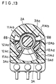
- FIG.13 is a sectional view showing a rotary variable resistor of another embodiment.
- two flexible protrusion 8B are provided on the rotary operation shaft 2A and arranged to be in contact with the stopping step portions 11Aa, 11Ab of the box-shape casing 1A, respectively. Therefore, the flexible protrusion 8B is in contact with the stopping step portion 11Aa or 11Ab immediately before contacting of the stopping protruding portion 12Aa or 12Ab with the stopping step portion 11Aa or 11Ab. Therefore, the rotary variable resistor shown in FIG.13 has the same effect as the third embodiment of FIG.12. In this embodiment shown in FIG.13, noise at the contact in the operation is reduced by the cushion effect of the flexible protrusion 8B.
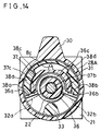
- FIG.14 shows a rotary manipulation-type variable resistor of still another embodiment in accordance with the present invention.
- the rotary manipulation-type variable resistor has the rotary operation shaft 28A integrally provided with a flexible protrusion 8c, which is provided to position in a recess equipped in the tubular holder 21.
- this flexible protrusion 8c is in contact with a step portion 38c or 38d of the tubular holder 21 immediately before contacting of the stopping step portion 32a or 32b of the rotary operation shaft 28A with the protrusion 33 of the tubular holder 21.
- the noise at the contact is reduced in the operation of the rotary operation shaft 28A.
- the flexible protrusion of the rotary operation shaft is in contact with the stopping step portion of the casing portion at the end of the turning angle range of the rotary operation shaft immediately before contacting of the stopping protruding portion of the rotary operation shaft and the stopping step portion of the casing with each other.
Landscapes
- Engineering & Computer Science (AREA)
- Microelectronics & Electronic Packaging (AREA)
- Adjustable Resistors (AREA)
Applications Claiming Priority (6)
| Application Number | Priority Date | Filing Date | Title |
|---|---|---|---|
| JP8840393 | 1993-04-15 | ||
| JP88403/93 | 1993-04-15 | ||
| JP12573793 | 1993-05-27 | ||
| JP125737/93 | 1993-05-27 | ||
| JP05252847A JP3141647B2 (ja) | 1993-04-15 | 1993-10-08 | 回転型電子部品 |
| JP252847/93 | 1993-10-08 |
Publications (3)
| Publication Number | Publication Date |
|---|---|
| EP0620568A2 true EP0620568A2 (de) | 1994-10-19 |
| EP0620568A3 EP0620568A3 (de) | 1995-03-01 |
| EP0620568B1 EP0620568B1 (de) | 1997-07-09 |
Family
ID=27305800
Family Applications (1)
| Application Number | Title | Priority Date | Filing Date |
|---|---|---|---|
| EP94105628A Expired - Lifetime EP0620568B1 (de) | 1993-04-15 | 1994-04-12 | Rotierende elektronische Vorrichtung |
Country Status (5)
| Country | Link |
|---|---|
| US (1) | US5469125A (de) |
| EP (1) | EP0620568B1 (de) |
| JP (1) | JP3141647B2 (de) |
| CN (1) | CN1038006C (de) |
| DE (1) | DE69404065T2 (de) |
Cited By (1)
| Publication number | Priority date | Publication date | Assignee | Title |
|---|---|---|---|---|
| CN103616555A (zh) * | 2013-11-07 | 2014-03-05 | 中联重科股份有限公司 | 电位计、发动机手油门控制系统及起重机 |
Families Citing this family (22)
| Publication number | Priority date | Publication date | Assignee | Title |
|---|---|---|---|---|
| JPH08153608A (ja) * | 1994-09-30 | 1996-06-11 | Aisin Seiki Co Ltd | 可変抵抗器 |
| JP4095383B2 (ja) * | 2002-09-04 | 2008-06-04 | キヤノン株式会社 | 撮像装置及びその制御方法並びに記憶媒体 |
| DE10323964B4 (de) * | 2003-05-27 | 2007-07-12 | Preh Gmbh | Haptische Begrenzung für einen Stufenschalter oder ein Potentiometer |
| JP4731936B2 (ja) * | 2005-02-09 | 2011-07-27 | 本田技研工業株式会社 | 回転式可変抵抗器 |
| JP4655953B2 (ja) * | 2006-02-14 | 2011-03-23 | パナソニック株式会社 | 制御器 |
| JP2008209918A (ja) * | 2007-02-02 | 2008-09-11 | Matsushita Electric Ind Co Ltd | 操作装置、およびその製造方法 |
| TWM357007U (en) * | 2008-12-17 | 2009-05-11 | Solteam Electronics Co Ltd | The drawing rotating device |
| JP5166363B2 (ja) * | 2009-06-30 | 2013-03-21 | 東京コスモス電機株式会社 | ポテンショメータ |
| JP5475618B2 (ja) * | 2010-11-12 | 2014-04-16 | 東京コスモス電機株式会社 | 非接触式角度センサ |
| JP5773762B2 (ja) * | 2011-06-03 | 2015-09-02 | キヤノン株式会社 | 電子機器 |
| JP5873297B2 (ja) * | 2011-11-02 | 2016-03-01 | 白光株式会社 | はんだ取扱装置 |
| US8576044B2 (en) * | 2011-11-04 | 2013-11-05 | Chapman/Leonard Studio Equipment, Inc. | Hand controller for a camera crane |
| WO2013093529A1 (en) * | 2011-12-20 | 2013-06-27 | Toth Matyas | Apparatus for on demand limiting of the value range of a parameter adjustment device |
| CN104754326B (zh) * | 2015-03-13 | 2017-05-24 | 北京科旭威尔科技股份有限公司 | 一种可精确定位摄像机变焦位置的机构 |
| CN108109858B (zh) * | 2018-01-22 | 2024-07-26 | 康士伯船舶电气(江苏)有限公司 | 一种控制多路开关信号的开关装置 |
| ES2728136B2 (es) * | 2018-04-20 | 2021-02-10 | Aragonesa De Componentes Pasivos S A | Mando de control retornable |
| CN109017606B (zh) * | 2018-08-31 | 2021-07-02 | 华勤技术股份有限公司 | 摄像头组件及包含其的汽车、摄像头组件的调节方法 |
| CN109428444A (zh) * | 2018-10-19 | 2019-03-05 | 浙江省东阳市东磁诚基电子有限公司 | 一种可变速铁芯振动马达 |
| US11009278B2 (en) * | 2018-12-10 | 2021-05-18 | Midea Group Co., Ltd. | Refrigerator with variable ice dispenser |
| US10845117B2 (en) | 2018-12-10 | 2020-11-24 | Midea Group Co., Ltd. | Refrigerator with variable fluid dispenser |
| CN111834073B (zh) * | 2020-06-22 | 2022-03-04 | 上海航天控制技术研究所 | 一种中空分体式导电塑料电位器 |
| JP7646391B2 (ja) * | 2021-02-25 | 2025-03-17 | キヤノン株式会社 | 撮像装置及び操作部材 |
Family Cites Families (13)
| Publication number | Priority date | Publication date | Assignee | Title |
|---|---|---|---|---|
| DE352408C (de) * | 1922-04-25 | Alfred Hoch | Gepaeckhalter | |
| US2143401A (en) * | 1937-10-07 | 1939-01-10 | Mallory & Co Inc P R | Interchangeable shaft for electrical devices |
| US2346598A (en) * | 1941-11-08 | 1944-04-11 | Clarostat Mfg Co Inc | Variable resistor |
| US2781436A (en) * | 1955-08-03 | 1957-02-12 | Chicago Telephone Supply Corp | Variable resistor with means for preventing shaft rattle |
| GB1165682A (en) * | 1966-05-06 | 1969-10-01 | Cossor Ltd A C | Improvements in Locking Knobs |
| US3902152A (en) * | 1969-09-18 | 1975-08-26 | Cts Corp | Electrical control having an insulated shaft extension |
| US3654581A (en) * | 1971-03-15 | 1972-04-04 | Beckman Instruments Inc | Rotor and shaft assembly for variable resistor |
| DE3112560C2 (de) * | 1981-03-30 | 1983-01-27 | M.A.N.- Roland Druckmaschinen AG, 6050 Offenbach | Näherungsschalter, der mittels Erregung und Erfassung eines Feldes das Vorhandensein oder Fehlen von feldverändernden Objekten in einem definierten Entfernungsbereich zum Näherungsschalter durch ein binäres Signal anzeigt |
| GB2174250B (en) * | 1983-04-07 | 1987-06-10 | Matsushita Electric Industrial Co Ltd | Rotary operation type miniaturixed electronic component |
| DE3524308A1 (de) * | 1985-07-06 | 1987-01-15 | Ruf Kg Wilhelm | Dreh - potentiometer |
| JPH01175201A (ja) * | 1987-12-28 | 1989-07-11 | Matsushita Electric Ind Co Ltd | 回転形ポテンショメータ |
| GB2217920A (en) * | 1988-04-29 | 1989-11-01 | Crystalate Electronics | Calibrated potentiometer |
| JP3039139B2 (ja) * | 1992-06-11 | 2000-05-08 | 松下電器産業株式会社 | シーソー操作型可変抵抗器 |
-
1993
- 1993-10-08 JP JP05252847A patent/JP3141647B2/ja not_active Expired - Fee Related
-
1994
- 1994-04-12 DE DE69404065T patent/DE69404065T2/de not_active Expired - Fee Related
- 1994-04-12 EP EP94105628A patent/EP0620568B1/de not_active Expired - Lifetime
- 1994-04-14 CN CN94104218A patent/CN1038006C/zh not_active Expired - Fee Related
- 1994-04-14 US US08/227,646 patent/US5469125A/en not_active Expired - Lifetime
Cited By (2)
| Publication number | Priority date | Publication date | Assignee | Title |
|---|---|---|---|---|
| CN103616555A (zh) * | 2013-11-07 | 2014-03-05 | 中联重科股份有限公司 | 电位计、发动机手油门控制系统及起重机 |
| CN103616555B (zh) * | 2013-11-07 | 2016-06-29 | 中联重科股份有限公司 | 电位计、发动机手油门控制系统及起重机 |
Also Published As
| Publication number | Publication date |
|---|---|
| DE69404065D1 (de) | 1997-08-14 |
| EP0620568A3 (de) | 1995-03-01 |
| DE69404065T2 (de) | 1997-10-30 |
| CN1106158A (zh) | 1995-08-02 |
| EP0620568B1 (de) | 1997-07-09 |
| US5469125A (en) | 1995-11-21 |
| CN1038006C (zh) | 1998-04-08 |
| JP3141647B2 (ja) | 2001-03-05 |
| JPH0745407A (ja) | 1995-02-14 |
Similar Documents
| Publication | Publication Date | Title |
|---|---|---|
| EP0620568B1 (de) | Rotierende elektronische Vorrichtung | |
| JP4019515B2 (ja) | 押圧・回動操作型電子部品およびこれを用いた通信端末機器 | |
| JP3222714B2 (ja) | 押圧・回転操作型電子部品 | |
| US6566619B2 (en) | Rocker switch with centering torsion spring | |
| US6525277B2 (en) | Multiple operation type input device | |
| JPH10326144A (ja) | 回転操作型電子部品 | |
| JPH1139998A (ja) | 回転型エンコーダ | |
| US6504115B2 (en) | Multidirectional input device | |
| JPH097462A (ja) | プッシュスイッチ付き回転操作型電子部品 | |
| US6849817B2 (en) | Switching device including stopper surface-mounted on printed circuit board | |
| JPH08115637A (ja) | 自動復帰式スライドスイッチおよびスライド構造 | |
| JP3300106B2 (ja) | 入力装置 | |
| JP3261873B2 (ja) | プッシュスイッチ付き回転操作型電子部品 | |
| JP2828045B2 (ja) | 車両用レバースイッチおよびその製造方法 | |
| JP4312041B2 (ja) | 二段押圧型スイッチ付き回転式電子部品 | |
| JP2539073Y2 (ja) | 押釦スイッチ付き回転式電子部品 | |
| JPH08286094A (ja) | 中立位置復帰型電子部品 | |
| JP2606991Y2 (ja) | スイッチ装置 | |
| JP3931532B2 (ja) | 多方向操作型電子部品及びそれを用いた電子機器 | |
| JP4471817B2 (ja) | 多機能型電子部品 | |
| CN221981540U (zh) | 阻尼可调的摇杆组件和游戏手柄 | |
| JP3539019B2 (ja) | 回転操作型電子部品 | |
| JPH0125365Y2 (de) | ||
| US6169473B1 (en) | Screw-driven multiturn electrical device | |
| JP2924656B2 (ja) | 押し釦スイッチ付きロータリースイッチ |
Legal Events
| Date | Code | Title | Description |
|---|---|---|---|
| PUAI | Public reference made under article 153(3) epc to a published international application that has entered the european phase |
Free format text: ORIGINAL CODE: 0009012 |
|
| AK | Designated contracting states |
Kind code of ref document: A2 Designated state(s): DE FR GB |
|
| PUAL | Search report despatched |
Free format text: ORIGINAL CODE: 0009013 |
|
| AK | Designated contracting states |
Kind code of ref document: A3 Designated state(s): DE FR GB |
|
| 17P | Request for examination filed |
Effective date: 19950308 |
|
| 17Q | First examination report despatched |
Effective date: 19951214 |
|
| GRAG | Despatch of communication of intention to grant |
Free format text: ORIGINAL CODE: EPIDOS AGRA |
|
| GRAH | Despatch of communication of intention to grant a patent |
Free format text: ORIGINAL CODE: EPIDOS IGRA |
|
| GRAH | Despatch of communication of intention to grant a patent |
Free format text: ORIGINAL CODE: EPIDOS IGRA |
|
| GRAA | (expected) grant |
Free format text: ORIGINAL CODE: 0009210 |
|
| AK | Designated contracting states |
Kind code of ref document: B1 Designated state(s): DE FR GB |
|
| ET | Fr: translation filed | ||
| REF | Corresponds to: |
Ref document number: 69404065 Country of ref document: DE Date of ref document: 19970814 |
|
| PLBE | No opposition filed within time limit |
Free format text: ORIGINAL CODE: 0009261 |
|
| STAA | Information on the status of an ep patent application or granted ep patent |
Free format text: STATUS: NO OPPOSITION FILED WITHIN TIME LIMIT |
|
| 26N | No opposition filed | ||
| REG | Reference to a national code |
Ref country code: GB Ref legal event code: IF02 |
|
| PGFP | Annual fee paid to national office [announced via postgrant information from national office to epo] |
Ref country code: FR Payment date: 20060410 Year of fee payment: 13 |
|
| PGFP | Annual fee paid to national office [announced via postgrant information from national office to epo] |
Ref country code: GB Payment date: 20060412 Year of fee payment: 13 |
|
| GBPC | Gb: european patent ceased through non-payment of renewal fee |
Effective date: 20070412 |
|
| PG25 | Lapsed in a contracting state [announced via postgrant information from national office to epo] |
Ref country code: GB Free format text: LAPSE BECAUSE OF NON-PAYMENT OF DUE FEES Effective date: 20070412 |
|
| PG25 | Lapsed in a contracting state [announced via postgrant information from national office to epo] |
Ref country code: FR Free format text: LAPSE BECAUSE OF NON-PAYMENT OF DUE FEES Effective date: 20070430 |
|
| PGFP | Annual fee paid to national office [announced via postgrant information from national office to epo] |
Ref country code: DE Payment date: 20090409 Year of fee payment: 16 |
|
| PG25 | Lapsed in a contracting state [announced via postgrant information from national office to epo] |
Ref country code: DE Free format text: LAPSE BECAUSE OF NON-PAYMENT OF DUE FEES Effective date: 20101103 |