EP0620610B1 - Batterie à trou traversant - Google Patents
Batterie à trou traversant Download PDFInfo
- Publication number
- EP0620610B1 EP0620610B1 EP19940105813 EP94105813A EP0620610B1 EP 0620610 B1 EP0620610 B1 EP 0620610B1 EP 19940105813 EP19940105813 EP 19940105813 EP 94105813 A EP94105813 A EP 94105813A EP 0620610 B1 EP0620610 B1 EP 0620610B1
- Authority
- EP
- European Patent Office
- Prior art keywords
- battery
- hole
- shaped
- electrode
- vessel
- Prior art date
- Legal status (The legal status is an assumption and is not a legal conclusion. Google has not performed a legal analysis and makes no representation as to the accuracy of the status listed.)
- Expired - Lifetime
Links
Images

Classifications
-
- H—ELECTRICITY
- H01—ELECTRIC ELEMENTS
- H01M—PROCESSES OR MEANS, e.g. BATTERIES, FOR THE DIRECT CONVERSION OF CHEMICAL ENERGY INTO ELECTRICAL ENERGY
- H01M10/00—Secondary cells; Manufacture thereof
- H01M10/04—Construction or manufacture in general
- H01M10/0431—Cells with wound or folded electrodes
-
- H—ELECTRICITY
- H01—ELECTRIC ELEMENTS
- H01M—PROCESSES OR MEANS, e.g. BATTERIES, FOR THE DIRECT CONVERSION OF CHEMICAL ENERGY INTO ELECTRICAL ENERGY
- H01M10/00—Secondary cells; Manufacture thereof
- H01M10/60—Heating or cooling; Temperature control
- H01M10/61—Types of temperature control
- H01M10/613—Cooling or keeping cold
-
- H—ELECTRICITY
- H01—ELECTRIC ELEMENTS
- H01M—PROCESSES OR MEANS, e.g. BATTERIES, FOR THE DIRECT CONVERSION OF CHEMICAL ENERGY INTO ELECTRICAL ENERGY
- H01M10/00—Secondary cells; Manufacture thereof
- H01M10/60—Heating or cooling; Temperature control
- H01M10/61—Types of temperature control
- H01M10/617—Types of temperature control for achieving uniformity or desired distribution of temperature
-
- H—ELECTRICITY
- H01—ELECTRIC ELEMENTS
- H01M—PROCESSES OR MEANS, e.g. BATTERIES, FOR THE DIRECT CONVERSION OF CHEMICAL ENERGY INTO ELECTRICAL ENERGY
- H01M10/00—Secondary cells; Manufacture thereof
- H01M10/60—Heating or cooling; Temperature control
- H01M10/64—Heating or cooling; Temperature control characterised by the shape of the cells
- H01M10/643—Cylindrical cells
-
- H—ELECTRICITY
- H01—ELECTRIC ELEMENTS
- H01M—PROCESSES OR MEANS, e.g. BATTERIES, FOR THE DIRECT CONVERSION OF CHEMICAL ENERGY INTO ELECTRICAL ENERGY
- H01M10/00—Secondary cells; Manufacture thereof
- H01M10/60—Heating or cooling; Temperature control
- H01M10/65—Means for temperature control structurally associated with the cells
- H01M10/655—Solid structures for heat exchange or heat conduction
- H01M10/6551—Surfaces specially adapted for heat dissipation or radiation, e.g. fins or coatings
-
- H—ELECTRICITY
- H01—ELECTRIC ELEMENTS
- H01M—PROCESSES OR MEANS, e.g. BATTERIES, FOR THE DIRECT CONVERSION OF CHEMICAL ENERGY INTO ELECTRICAL ENERGY
- H01M10/00—Secondary cells; Manufacture thereof
- H01M10/60—Heating or cooling; Temperature control
- H01M10/65—Means for temperature control structurally associated with the cells
- H01M10/655—Solid structures for heat exchange or heat conduction
- H01M10/6554—Rods or plates
- H01M10/6555—Rods or plates arranged between the cells
-
- H—ELECTRICITY
- H01—ELECTRIC ELEMENTS
- H01M—PROCESSES OR MEANS, e.g. BATTERIES, FOR THE DIRECT CONVERSION OF CHEMICAL ENERGY INTO ELECTRICAL ENERGY
- H01M50/00—Constructional details or processes of manufacture of the non-active parts of electrochemical cells other than fuel cells, e.g. hybrid cells
- H01M50/50—Current conducting connections for cells or batteries
-
- Y—GENERAL TAGGING OF NEW TECHNOLOGICAL DEVELOPMENTS; GENERAL TAGGING OF CROSS-SECTIONAL TECHNOLOGIES SPANNING OVER SEVERAL SECTIONS OF THE IPC; TECHNICAL SUBJECTS COVERED BY FORMER USPC CROSS-REFERENCE ART COLLECTIONS [XRACs] AND DIGESTS
- Y02—TECHNOLOGIES OR APPLICATIONS FOR MITIGATION OR ADAPTATION AGAINST CLIMATE CHANGE
- Y02E—REDUCTION OF GREENHOUSE GAS [GHG] EMISSIONS, RELATED TO ENERGY GENERATION, TRANSMISSION OR DISTRIBUTION
- Y02E60/00—Enabling technologies; Technologies with a potential or indirect contribution to GHG emissions mitigation
- Y02E60/10—Energy storage using batteries
-
- Y—GENERAL TAGGING OF NEW TECHNOLOGICAL DEVELOPMENTS; GENERAL TAGGING OF CROSS-SECTIONAL TECHNOLOGIES SPANNING OVER SEVERAL SECTIONS OF THE IPC; TECHNICAL SUBJECTS COVERED BY FORMER USPC CROSS-REFERENCE ART COLLECTIONS [XRACs] AND DIGESTS
- Y02—TECHNOLOGIES OR APPLICATIONS FOR MITIGATION OR ADAPTATION AGAINST CLIMATE CHANGE
- Y02P—CLIMATE CHANGE MITIGATION TECHNOLOGIES IN THE PRODUCTION OR PROCESSING OF GOODS
- Y02P70/00—Climate change mitigation technologies in the production process for final industrial or consumer products
- Y02P70/50—Manufacturing or production processes characterised by the final manufactured product
Definitions
- This invention relates to a battery according to the preamble of claim 1.
- a battery having a through-hole is discloded in US-A-4,262,064 (or FR-A-53 670).
- Such a battery is subject to storage of heat and rise in temperature due to the heat of reaction of the electrodes resulting from charging/discharging and the Joule heat by the current flowing through the electrodes or the current collectors.
- a cooling fluid may be caused to flow through the through-hole of the battery or through a passage for a cooling fluid (EP-A-0 044 753).
- a cooling fluid EP-A-0 044 753
- the energy density of the electric source system in its entirety is lowered due to the increase in volume or weight caused by the provision of the cooling system.
- the present invention provides a battery in which a through-hole traversing a main battery body and opened to outside is formed at a central region of the main battery body, wherein at least one thin metal plate is inserted and secured within the through-hole.
- the through-hole and at least one thin metal plate is inserted and secured within the through-hole is formed as heat dissipating means, while there is no necessity of providing complex cooling means for heat dissipation. Consequently, the energy density is not lowered due to the weight or the capacity of the cooling means. Also, the surface area of the battery may be maintained without the necessity of using a planar or elongated shape of the battery, so that the battery itself is not lowered in strength.
- heat dissipating fins around the opening end of the through-hole, heat dissipation may be improved further, whereas the heat generated by charging/discharging of large current may be efficiently dissipated.
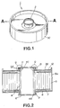
- Fig. 1 is a schematic perspective view showing an embodiment of a columnar-shaped battery according to the present invention, but without showing the thin metal plates in the through-hole.
- Fig. 2 is a schematic cross-sectional view showing the inner structure of the columnar-shaped battery shown in Fig.1 during the fabrication process.
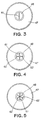
- Fig. 3 is a plan view showing the state in which a thin metal plate is mounted in a through-hole.
- Fig. 4 is a plan view showing the state in which two thin metal plates are mounted in a through-hole.
- Fig. 5 is a plan view showing the state in which four thin metal plates are mounted in a through-hole.
- Fig. 6 is a plan view showing the state in which six thin metal plates are mounted in a through-hole.
- Fig. 7 is a side view showing a sealing plate having a heat-dissipating fin.
- the battery of the present invention includes a through-hole formed at the center of a main battery body so as to be opened to outside.
- the through-hole is formed by winding a strip-shaped positive electrode and a strip-shaped negative electrode about a cylindrical core a number of times with a separator in-between to form a spiral-shaped electrode and mounting the spiral-shaped electrode in a battery vessel having a central opening so that an opening of the cylindrical core is substantially coincident with the central opening of the battery vessel.
- the cylindrical core may be constituted by an electric conductor and electrically insulated from the battery vessel, while being electrically connected to one of the positive electrode and the negative electrode of the spiral-shaped electrode so as to be used as a battery electrode.
- the battery vessel may be used as an oppositely poled battery electrode (see Figs. 3 to 7).
- One or more thin metal plates are inserted into and secured in the through-hole, and additionally radial heat-dissipating fins may be formed around the opening end of the through-hole for further improving the heat dissipation properties.
- the present invention may be applied to any type of the batteries. However, it is preferably applied to a high-output non-aqueous electrolyte secondary battery.
- a large-sized non-aqueous electrolyte secondary battery is required to cope with the charging/discharging of a larger currant.
- a lithium secondary battery employing a non-aqueous solvent is designed to accommodate large current through various improvements because the electrical conductivity of the liquid electrolyte is extremely low as compared to that of the aqueous solution. It is however feared that considerable amount of heat may be generated under the conditions of charging/discharging the larger current.
- the non-aqueous electrolyte secondary battery may be constructed in any desirable manner.
- LiM I x M II 1-x O 2 where M I and M II each denote one of metals selected from the group consisting of Co, Ni, Mn, Fe, Cr and V, may be used as an active positive electrode material, while a carbon material capable of doping and de-doping Li may be used as an active negative electrode material.
- TiS 2 , MoS 2 , V 2 O 5 or r V 3 O 6 may be used as an active positive electrodematerial, while metal lithium or a lithium alloy may be used as an active negative material.
- sulfur and sodium may be used as an active positive electrode material and as an active negative electrode material, respectively.
- Fig. 1 is a perspective view showing a columnar-shaped battery of the present embodiment.
- Fig. 2 is a schematic cross-sectional view showing the inner structure of the columnar-shaped battery shown in Fig. 1.
- a battery 1 according to the present embodiment has a through-hole 2 at the center opened on both the upper and lower surfaces thereof, as shown in the perspective view of Fig. 1.
- the battery 1 is made up of a lower negative electrode casing 3A, an upper negative electrode casing 3B, a cylindrical-shaped positive electrode core 4 and a spiral-shaped electrode 5 having positive and negative electrodes.
- a battery half is indicated by a reference numeral 1A.
- the lower negative electrode casing 3A is formed as a cup having a circular opening 6 at a mid part of the bottom thereof.
- the upper negative electrode casing 3B is planar and has a circular opening 11 at the center thereof, as shown in Fig. 2.
- the cylindrical-shaped positive electrode core 4 has its length slightly longer than the depth of the lower negative electrode casing 3A, and is provided with an upper flange 4A and a lower flange 4B.
- a female screw 4C having a length of approximately 5 mm is tapped beginning from the opening end of the inner periphery of the cylindrical-shaped positive electrode core 4 of the flange 4A.
- the spiral-shaped electrode 5 is formed by winding strip-shaped positive and negative electrodes with an interposed separator a large number of times around the periphery of the cylindrical-shaped positive electrode core 4, so that the positive and negative electrodes face each other with the interposition of the separator.
- a lower insulator 8 is placed on the bottom of the lower negative electrode casing 3A.
- a positive electrode lead 7 is welded to the spiral-shaped electrode 5 in the state shown in Fig. 2.
- the spiral-shaped electrode 5 in this state is mounted on the lower negative electrode casing 3A, by fitting the flange 4B of the centrally disposed cylindrical-shaped positive electrode core 4 in the opening 6 of the lower negative electrodecasing 3A so that the flange 4B is protruded downwards from the bottom of the lower negative electrode casing 3A.
- the flange 4B protruded downwards is caulked to the opening 6 by means of a lower gasket 9 at P in Fig. 2 for sealing the one side of the battery half.
- a negative electrode is then welded by a negative electrode lead 10 to the inner periphery of the lower negative electrode casing 3A.
- an upper insulator 12 is placed on the casing 3A.
- the upper negative electrode casing 3B is placed on the upper insulator 12 so that the upper end of the cylindrical-shaped positive electrode core 4 is protruded via an opening 11 of the upper negative electrode casing 3B.
- the upper negative electrode casing 3B and the lower negative electrode casing 3A are connected to each other along the outer peripheral surfaces thereof.
- the upwardly protruded flange 4A of the cylindrical-shaped positive electrode core 4 is caulked to the opening 11 of the upper negative electode casing 3B at Q in Fig. 2 to complete the sealing.
- the battery of the present embodiment has the central through-hole 2 so that it is similar in shape to a cylinder.
- An aluminum plate 61, 1 mm in thickness, 16 mm in width and 200 mm in length was mounted within the battery winding core 48 as shown in Fig. 3 to provide a sample 1.
- a battery having the inside of the battery winding core 48 remaining hollow was also prepared as a comparison sample 1.
- the battery employed in the present example was the same in structure as the battery of he previous one. However, a sealing plate having heat-dissipating fins is used as a battery lid instead of mounting one or more heat-dissipating thin plates within the cylinder.
- a sealing plate 71 formed of, for example, aluminum includes a disc-shaped lid 72 acting as a battery lid, a center opening 73 passed through by the battery winding core 48, and heat-radiating fins 74 arranged radially around the center opening 73 as the center, as shown in Fig. 7.
- the heat radiating fins 74 are higher in height at the center and become lower in height towards the outer periphery.
- the sealing plate 71 was secured with a set screw in place of the battery lid 47.
- Four, six, eight and twelve heat-dissipating fins 74 may be used respectively.
- the heat-dissipating fins of the sealing plate provide an additional advantage that these may be utilized as connecting points for lead welding during battery connection. If a number of the above-described batteries are used as a battery set, the fact that the heat-dissipating fins of the sealing plate may be utilized as the structure for electrical connection means that ease in electrical connection of the batteries and suppression of heat evolution in the batteries may be realized simultaneously. Thus the properties of control equipment annexed to the batteries may be prevented from being lowered for suppressing accelerated deterioration of the battery service life.
- the battery of the present invention has many advantages, such as superior heat dissipation or high strength and energy density.
Landscapes
- Chemical & Material Sciences (AREA)
- Chemical Kinetics & Catalysis (AREA)
- Electrochemistry (AREA)
- General Chemical & Material Sciences (AREA)
- Engineering & Computer Science (AREA)
- Manufacturing & Machinery (AREA)
- Secondary Cells (AREA)
- Sealing Battery Cases Or Jackets (AREA)
- Gas Exhaust Devices For Batteries (AREA)
- Connection Of Batteries Or Terminals (AREA)
Claims (6)
- Batterie (1) ayant un trou débouchant (2) dans une zone médiane d'un corps principal de batterie, ledit trou débouchant (2) traversant le corps principal de la batterie et étant ouvert sur l'extérieur, caractérisée en ce que au moins une plaque métallique mince (61, 62) est insérée et fixée dans le trou débouchant (2).
- Batterie selon la revendication 1, dans laquelle la paroi interne du trou débouchant (2) est utilisée comme une des électrodes.
- Batterie selon la revendication 1, dans laquelle une bague électriquement conductrice est reliée à la paroi interne de l'extrémité d'ouverture du trou débouchant (2) pour un raccordement électrique vers l'extérieur.
- Batterie selon la revendication 1, dans laquelle ledit corps de batterie comporteune cuve de batterie ayant une ouverture centrale comme dit trou débouchant (2), etune électrode en forme de spirale constituée d'une électrode positive en forme de bande et d'une électrode négative en forme de bande enroulées autour d'une partie cylindrique plusieurs fois avec un séparateur entre elles, ladite électrode en forme de spirale étant montée dans ladite cuve de batterie de telle sorte qu'une ouverture de la partie cylindrique coïncide sensiblement avec ladite ouverture centrale, ladite cuve de batterie étant scellée après chargement d'un électrolyte liquide.
- Batterie selon la revendication 4, dans laquelle ladite partie cylindrique est formée par une matière électriquement conductrice et isolée électriquement par rapport à la cuve de batterie, et dans laquelle l'électrode positive ou l'électrode négative de l'électrode en forme de spirale est reliée électriquement à ladite partie cylindrique.
- Batterie selon la revendication 5, dans laquelle la cuve de batterie est de forme cylindrique et a son extrémité d'ouverture scellée avec une plaque d'étanchéité (47; 71), et dans laquelle l'autre électrode de l'électrode en forme de spirale est reliée électriquement à ladite cuve de batterie.
Applications Claiming Priority (4)
| Application Number | Priority Date | Filing Date | Title |
|---|---|---|---|
| JP8770993 | 1993-04-15 | ||
| JP87709/93 | 1993-04-15 | ||
| JP20377893A JPH06349460A (ja) | 1993-04-15 | 1993-07-27 | 電 池 |
| JP203778/93 | 1993-07-27 |
Publications (2)
| Publication Number | Publication Date |
|---|---|
| EP0620610A1 EP0620610A1 (fr) | 1994-10-19 |
| EP0620610B1 true EP0620610B1 (fr) | 1997-06-25 |
Family
ID=26428956
Family Applications (1)
| Application Number | Title | Priority Date | Filing Date |
|---|---|---|---|
| EP19940105813 Expired - Lifetime EP0620610B1 (fr) | 1993-04-15 | 1994-04-14 | Batterie à trou traversant |
Country Status (5)
| Country | Link |
|---|---|
| US (1) | US5501916A (fr) |
| EP (1) | EP0620610B1 (fr) |
| JP (1) | JPH06349460A (fr) |
| CA (1) | CA2121225C (fr) |
| DE (1) | DE69403930T2 (fr) |
Cited By (1)
| Publication number | Priority date | Publication date | Assignee | Title |
|---|---|---|---|---|
| US6245457B1 (en) | 1999-06-11 | 2001-06-12 | Alcatel | Bussing structure in an electrochemical cell |
Families Citing this family (52)
| Publication number | Priority date | Publication date | Assignee | Title |
|---|---|---|---|---|
| FR2752089B1 (fr) * | 1996-07-30 | 1998-09-04 | Accumulateurs Fixes | Generateur electrochimique cylindrique |
| FR2752092A1 (fr) * | 1996-07-30 | 1998-02-06 | Accumulateurs Fixes | Generateur electrochimique a electrodes spiralees |
| DE19721348A1 (de) * | 1997-05-22 | 1998-11-26 | Varta Batterie | Mehrzelliger Akkumulator |
| DE69800291T2 (de) * | 1997-06-27 | 2001-04-26 | Kabushiki Kaisha Toyota Chuo Kenkyusho, Nagakute | Zylinderförmiger Akkumulator |
| US6020084A (en) * | 1998-02-17 | 2000-02-01 | Alcatel | Electrochemical cell design with a hollow core |
| FR2796205B1 (fr) | 1999-07-08 | 2001-10-05 | Cit Alcatel | Accumulateur electrochimique etanche comportant un dispositif de reprise de courant en aluminium |
| US6844110B2 (en) | 2000-05-24 | 2005-01-18 | Ngk Insulators, Ltd. | Lithium secondary cell and assembly thereof |
| EP1213783A1 (fr) | 2000-12-08 | 2002-06-12 | Renata AG | Batterie à électrodes bobinées avec dissipateur de chaleur |
| JP4204237B2 (ja) * | 2001-03-21 | 2009-01-07 | 日本碍子株式会社 | リチウム二次単電池およびリチウム二次単電池の接続構造体 |
| US6677076B2 (en) * | 2002-01-15 | 2004-01-13 | Quallion Llc | Electric storage battery construction and method of manufacture |
| US6670071B2 (en) | 2002-01-15 | 2003-12-30 | Quallion Llc | Electric storage battery construction and method of manufacture |
| JP4461686B2 (ja) * | 2003-02-13 | 2010-05-12 | トヨタ自動車株式会社 | 二次電池、その製造装置および製造方法 |
| US8632898B2 (en) * | 2003-10-28 | 2014-01-21 | Johnson Controls Technology Company | Battery system including batteries that have a plurality of positive terminals and a plurality of negative terminals |
| US8080329B1 (en) | 2004-03-25 | 2011-12-20 | Quallion Llc | Uniformly wound battery |
| US7592097B2 (en) * | 2004-04-26 | 2009-09-22 | Greatbatch Ltd. | Electrochemical cell designs with anode plates and connections which facilitate heat dissipation |
| US8546009B2 (en) * | 2006-01-25 | 2013-10-01 | Tulsee Satish Doshi | Method and apparatus for thermal energy transfer |
| US20070247786A1 (en) * | 2006-04-24 | 2007-10-25 | Aamodt Paul B | Torroidal battery for use in implantable medical device |
| JP4438784B2 (ja) * | 2006-08-25 | 2010-03-24 | トヨタ自動車株式会社 | 蓄電装置 |
| DE102006047926A1 (de) * | 2006-10-10 | 2008-04-17 | Robert Bosch Gmbh | Batterievorrichtung mit wenigstens einer Batteriezelle |
| DE102007010750B3 (de) * | 2007-02-27 | 2008-09-04 | Daimler Ag | Elektrochemische Einzelzelle für eine Batterie, Verwendung einer Einzelzelle und Verwendung einer Batterie |
| IT1390612B1 (it) * | 2008-07-28 | 2011-09-09 | Univ Siena | Sensore amperometrico elettrochimico a tre elettrodi. |
| DE102008044162A1 (de) * | 2008-11-28 | 2010-06-02 | Robert Bosch Gmbh | Batterie |
| CN101577344B (zh) * | 2009-06-11 | 2011-04-20 | 珠海银通交通能源投资有限公司 | 动力电池 |
| CN101958432B (zh) | 2009-07-17 | 2013-03-13 | 清华大学 | 组合电池及其所用的环形电池 |
| CN102035040B (zh) * | 2009-09-28 | 2013-05-01 | 清华大学 | 制造组合电池的方法及组合电池 |
| CN101867049B (zh) * | 2010-06-17 | 2013-01-23 | 惠州亿纬锂能股份有限公司 | 锂电池 |
| US8728651B2 (en) | 2010-08-30 | 2014-05-20 | Highwater Innovations, Llc | Low aspect ratio spiral-wound VRLA battery |
| JP3166283U (ja) * | 2010-09-07 | 2011-02-24 | 佑正 許 | 放熱作用を有する充電池 |
| EP2659540B1 (fr) * | 2010-12-31 | 2018-03-07 | Shenzhen BYD Auto R&D Company Limited | Batterie |
| CN102751466B (zh) * | 2011-04-22 | 2016-02-03 | 比亚迪股份有限公司 | 一种电池 |
| US9028998B2 (en) | 2011-05-27 | 2015-05-12 | General Electric Company | Battery cell design and method of cooling battery cells |
| US20120301768A1 (en) * | 2011-05-27 | 2012-11-29 | General Electric Company | Battery cell design and method of cooling battery cells |
| CN103545570A (zh) * | 2012-07-13 | 2014-01-29 | 上海通用汽车有限公司 | 一种空气冷却式电池单体、电池以及车辆 |
| JP5751235B2 (ja) * | 2012-10-19 | 2015-07-22 | トヨタ自動車株式会社 | 電池用電極の製造方法及び装置 |
| FR3004292B1 (fr) * | 2013-04-09 | 2016-06-24 | Commissariat Energie Atomique | Accumulateur electrochimique au lithium avec boitier a dissipation thermique amelioree, pack-batterie et procedes de realisation associes. |
| US9622294B1 (en) | 2014-04-02 | 2017-04-11 | The United States Of America As Represented By The Secretary Of The Navy | Device for simulating thermal characteristics of a lithium-ion battery |
| CN105637696A (zh) * | 2014-07-14 | 2016-06-01 | 橙力电池株式会社 | 中空型二次电池 |
| KR102046056B1 (ko) | 2014-08-21 | 2019-11-18 | 주식회사 엘지화학 | 냉각 성능이 개선된 전지셀 |
| US10164304B1 (en) | 2014-10-31 | 2018-12-25 | The United States Of America, As Represented By The Secretary Of The Navy | Thermally dissipative electrochemical cell |
| AT517165A1 (de) * | 2015-04-30 | 2016-11-15 | Smartbow Gmbh | Batterie |
| EP3276701A1 (fr) * | 2016-07-26 | 2018-01-31 | VARTA Microbattery GmbH | Cellule electrochimique et dispositif comprenant ladite cellule |
| US10396315B2 (en) | 2016-12-30 | 2019-08-27 | Microsoft Technology Licensing, Llc | Hollow-core rolled-electrode battery cell |
| FR3075478B1 (fr) * | 2017-12-14 | 2019-12-13 | Commissariat A L'energie Atomique Et Aux Energies Alternatives | Sous-ensemble integrant un mandrin creux et une partie d'une traversee creuse formant borne pour accumulateur electrochimique metal-ion, accumulateur associe |
| CN109088126B (zh) * | 2018-08-09 | 2021-06-15 | 中南大学 | 大容量电芯电池及储能装置 |
| US20200168963A1 (en) * | 2018-11-28 | 2020-05-28 | Sf Motors, Inc. | Electric vehicle battery cell heat transfer system and method |
| FR3104824B1 (fr) * | 2019-12-13 | 2022-03-11 | Renault Sas | Pack de batterie avec circuit de refroidissement |
| WO2021192666A1 (fr) * | 2020-03-26 | 2021-09-30 | 三洋電機株式会社 | Batterie secondaire à électrolyte non aqueux |
| CN116210109A (zh) * | 2020-09-17 | 2023-06-02 | 株式会社村田制作所 | 二次电池 |
| CN112331895B (zh) * | 2020-09-30 | 2022-07-12 | 天津力神电池股份有限公司 | 一种电池 |
| EP4007038A4 (fr) * | 2020-09-30 | 2023-05-03 | Tianjin Lishen Battery Joint-Stock Co., Ltd. | Ensemble bloc de type broche pour batterie au lithium-ion |
| CN112382784B (zh) * | 2020-11-14 | 2021-08-03 | 南京工业大学 | 一种降低热失控风险的嵌套结构锂离子电池 |
| CN118645735B (zh) * | 2024-08-14 | 2024-11-22 | 深圳赛骄阳能源科技股份有限公司 | 一种工业储能电池组散热装置 |
Family Cites Families (11)
| Publication number | Priority date | Publication date | Assignee | Title |
|---|---|---|---|---|
| US2385127A (en) * | 1944-10-21 | 1945-09-18 | Carlile & Doughty Inc | Battery jar |
| NL133825C (fr) * | 1966-07-25 | |||
| US3682706A (en) * | 1970-06-18 | 1972-08-08 | Michel N Yardney | Gas depolarized cell |
| WO1979000229A1 (fr) * | 1977-10-24 | 1979-05-03 | Chloride Group Ltd | Accumulateurs electriques |
| US4189527A (en) * | 1979-01-17 | 1980-02-19 | The United States Of America As Represented By The Secretary Of The Air Force | Spherical heat pipe metal-hydrogen cell |
| US4262064A (en) * | 1980-03-28 | 1981-04-14 | The United States Of America As Represented By The Administrator Of The National Aeronautics And Space Administration | Toroidal cell and battery |
| AU7309281A (en) * | 1980-07-23 | 1982-01-28 | Chloride Silent Power Ltd. | Electrochemical storage batteries and modules therefor |
| FR2679382B1 (fr) * | 1991-07-15 | 1996-12-13 | Accumulateurs Fixes | Generateur electrochimique de forte energie massique specifique. |
| US5183222A (en) * | 1991-08-12 | 1993-02-02 | Tacticon Corp. | Electric powered tip-driven fan with metal/air battery assembly therefor |
| JPH05166533A (ja) * | 1991-12-13 | 1993-07-02 | Yuasa Corp | 積層薄形電池の集合構造 |
| US5288564A (en) * | 1992-09-30 | 1994-02-22 | Magnavox Electronic Systems Company | Compact, cylindrical, multi-cell seawater battery |
-
1993
- 1993-07-27 JP JP20377893A patent/JPH06349460A/ja not_active Withdrawn
-
1994
- 1994-04-13 CA CA 2121225 patent/CA2121225C/fr not_active Expired - Fee Related
- 1994-04-14 EP EP19940105813 patent/EP0620610B1/fr not_active Expired - Lifetime
- 1994-04-14 DE DE69403930T patent/DE69403930T2/de not_active Expired - Lifetime
- 1994-04-15 US US08/228,260 patent/US5501916A/en not_active Expired - Lifetime
Cited By (1)
| Publication number | Priority date | Publication date | Assignee | Title |
|---|---|---|---|---|
| US6245457B1 (en) | 1999-06-11 | 2001-06-12 | Alcatel | Bussing structure in an electrochemical cell |
Also Published As
| Publication number | Publication date |
|---|---|
| CA2121225A1 (fr) | 1994-10-16 |
| US5501916A (en) | 1996-03-26 |
| EP0620610A1 (fr) | 1994-10-19 |
| DE69403930T2 (de) | 1998-01-29 |
| DE69403930D1 (de) | 1997-07-31 |
| CA2121225C (fr) | 2004-09-28 |
| JPH06349460A (ja) | 1994-12-22 |
Similar Documents
| Publication | Publication Date | Title |
|---|---|---|
| CA2121225C (fr) | Batterie a trou de traversee et un dispositif de dissipation de chaleur | |
| EP2425485B1 (fr) | Batterie modulaire haute tension avec module de cellule électriquement isolé et périphéries d'interconnecteur | |
| JP4433650B2 (ja) | リチウム二次単電池及びリチウム二次単電池の接続構造体 | |
| US6913852B2 (en) | Battery module and container for battery module | |
| JP3203623B2 (ja) | 有機電解液電池 | |
| US7736793B2 (en) | Secondary battery with collector plate and electrode package thereof | |
| US6020084A (en) | Electrochemical cell design with a hollow core | |
| US20080026291A1 (en) | Rechargeable battery | |
| JP2004111300A (ja) | 非水電解質二次電池 | |
| US4957830A (en) | Rechargeable metal oxide-hydrogen battery | |
| KR101320581B1 (ko) | 이차 전지 | |
| JPH09231950A (ja) | 密閉された角型蓄電池 | |
| KR20190065077A (ko) | 열전도성 수지로 채워진 중공을 가지는 이차전지 | |
| EP1810362B1 (fr) | Batteries de puissance secondaire au lithium-ion de type a assemblage de spires | |
| US20050042508A1 (en) | Secondary battery | |
| US20080248383A1 (en) | Battery module | |
| KR100277651B1 (ko) | 원통형 전지의 열 발산장치 | |
| CN218957853U (zh) | 一种大容量电池 | |
| KR100824851B1 (ko) | 전극 조립체 및 이를 구비하는 이차 전지 | |
| US3250645A (en) | Annular electric cell having central apparatus space | |
| KR100788559B1 (ko) | 이차전지 | |
| JPH11273644A (ja) | 組電池及び組電池用収容体 | |
| JP3902330B2 (ja) | 円筒形電池 | |
| JP3804701B2 (ja) | 組電池用リチウム電池および組電池 | |
| JPH10247513A (ja) | 油漬均圧型蓄電池 |
Legal Events
| Date | Code | Title | Description |
|---|---|---|---|
| PUAI | Public reference made under article 153(3) epc to a published international application that has entered the european phase |
Free format text: ORIGINAL CODE: 0009012 |
|
| AK | Designated contracting states |
Kind code of ref document: A1 Designated state(s): DE FR GB |
|
| 17P | Request for examination filed |
Effective date: 19950317 |
|
| 17Q | First examination report despatched |
Effective date: 19951020 |
|
| GRAG | Despatch of communication of intention to grant |
Free format text: ORIGINAL CODE: EPIDOS AGRA |
|
| GRAH | Despatch of communication of intention to grant a patent |
Free format text: ORIGINAL CODE: EPIDOS IGRA |
|
| GRAH | Despatch of communication of intention to grant a patent |
Free format text: ORIGINAL CODE: EPIDOS IGRA |
|
| GRAA | (expected) grant |
Free format text: ORIGINAL CODE: 0009210 |
|
| AK | Designated contracting states |
Kind code of ref document: B1 Designated state(s): DE FR GB |
|
| REF | Corresponds to: |
Ref document number: 69403930 Country of ref document: DE Date of ref document: 19970731 |
|
| ET | Fr: translation filed | ||
| PLBE | No opposition filed within time limit |
Free format text: ORIGINAL CODE: 0009261 |
|
| STAA | Information on the status of an ep patent application or granted ep patent |
Free format text: STATUS: NO OPPOSITION FILED WITHIN TIME LIMIT |
|
| 26N | No opposition filed | ||
| REG | Reference to a national code |
Ref country code: GB Ref legal event code: IF02 |
|
| PGFP | Annual fee paid to national office [announced via postgrant information from national office to epo] |
Ref country code: FR Payment date: 20110510 Year of fee payment: 18 Ref country code: DE Payment date: 20110421 Year of fee payment: 18 |
|
| PGFP | Annual fee paid to national office [announced via postgrant information from national office to epo] |
Ref country code: GB Payment date: 20110421 Year of fee payment: 18 |
|
| GBPC | Gb: european patent ceased through non-payment of renewal fee |
Effective date: 20120414 |
|
| REG | Reference to a national code |
Ref country code: FR Ref legal event code: ST Effective date: 20121228 |
|
| PG25 | Lapsed in a contracting state [announced via postgrant information from national office to epo] |
Ref country code: GB Free format text: LAPSE BECAUSE OF NON-PAYMENT OF DUE FEES Effective date: 20120414 |
|
| REG | Reference to a national code |
Ref country code: DE Ref legal event code: R119 Ref document number: 69403930 Country of ref document: DE Effective date: 20121101 |
|
| PG25 | Lapsed in a contracting state [announced via postgrant information from national office to epo] |
Ref country code: FR Free format text: LAPSE BECAUSE OF NON-PAYMENT OF DUE FEES Effective date: 20120430 |
|
| PG25 | Lapsed in a contracting state [announced via postgrant information from national office to epo] |
Ref country code: DE Free format text: LAPSE BECAUSE OF NON-PAYMENT OF DUE FEES Effective date: 20121101 |