EP0620619A2 - Méthode de production de pont de court-circuit pour assemblage de fiche modulaire - Google Patents
Méthode de production de pont de court-circuit pour assemblage de fiche modulaire Download PDFInfo
- Publication number
- EP0620619A2 EP0620619A2 EP94302472A EP94302472A EP0620619A2 EP 0620619 A2 EP0620619 A2 EP 0620619A2 EP 94302472 A EP94302472 A EP 94302472A EP 94302472 A EP94302472 A EP 94302472A EP 0620619 A2 EP0620619 A2 EP 0620619A2
- Authority
- EP
- European Patent Office
- Prior art keywords
- contacts
- modular jack
- insert
- relationship
- shorting
- Prior art date
- Legal status (The legal status is an assumption and is not a legal conclusion. Google has not performed a legal analysis and makes no representation as to the accuracy of the status listed.)
- Withdrawn
Links
Images


Classifications
-
- H—ELECTRICITY
- H01—ELECTRIC ELEMENTS
- H01R—ELECTRICALLY-CONDUCTIVE CONNECTIONS; STRUCTURAL ASSOCIATIONS OF A PLURALITY OF MUTUALLY-INSULATED ELECTRICAL CONNECTING ELEMENTS; COUPLING DEVICES; CURRENT COLLECTORS
- H01R43/00—Apparatus or processes specially adapted for manufacturing, assembling, maintaining, or repairing of line connectors or current collectors or for joining electric conductors
- H01R43/20—Apparatus or processes specially adapted for manufacturing, assembling, maintaining, or repairing of line connectors or current collectors or for joining electric conductors for assembling or disassembling contact members with insulating base, case or sleeve
- H01R43/24—Assembling by moulding on contact members
-
- H—ELECTRICITY
- H01—ELECTRIC ELEMENTS
- H01R—ELECTRICALLY-CONDUCTIVE CONNECTIONS; STRUCTURAL ASSOCIATIONS OF A PLURALITY OF MUTUALLY-INSULATED ELECTRICAL CONNECTING ELEMENTS; COUPLING DEVICES; CURRENT COLLECTORS
- H01R29/00—Coupling parts for selective co-operation with a counterpart in different ways to establish different circuits, e.g. for voltage selection, for series-parallel selection, programmable connectors
-
- H—ELECTRICITY
- H01—ELECTRIC ELEMENTS
- H01R—ELECTRICALLY-CONDUCTIVE CONNECTIONS; STRUCTURAL ASSOCIATIONS OF A PLURALITY OF MUTUALLY-INSULATED ELECTRICAL CONNECTING ELEMENTS; COUPLING DEVICES; CURRENT COLLECTORS
- H01R2201/00—Connectors or connections adapted for particular applications
- H01R2201/16—Connectors or connections adapted for particular applications for telephony
-
- H—ELECTRICITY
- H01—ELECTRIC ELEMENTS
- H01R—ELECTRICALLY-CONDUCTIVE CONNECTIONS; STRUCTURAL ASSOCIATIONS OF A PLURALITY OF MUTUALLY-INSULATED ELECTRICAL CONNECTING ELEMENTS; COUPLING DEVICES; CURRENT COLLECTORS
- H01R24/00—Two-part coupling devices, or either of their cooperating parts, characterised by their overall structure
- H01R24/60—Contacts spaced along planar side wall transverse to longitudinal axis of engagement
- H01R24/62—Sliding engagements with one side only, e.g. modular jack coupling devices
- H01R24/64—Sliding engagements with one side only, e.g. modular jack coupling devices for high frequency, e.g. RJ 45
-
- H—ELECTRICITY
- H01—ELECTRIC ELEMENTS
- H01R—ELECTRICALLY-CONDUCTIVE CONNECTIONS; STRUCTURAL ASSOCIATIONS OF A PLURALITY OF MUTUALLY-INSULATED ELECTRICAL CONNECTING ELEMENTS; COUPLING DEVICES; CURRENT COLLECTORS
- H01R31/00—Coupling parts supported only by co-operation with counterpart
- H01R31/08—Short-circuiting members for bridging contacts in a counterpart
-
- Y—GENERAL TAGGING OF NEW TECHNOLOGICAL DEVELOPMENTS; GENERAL TAGGING OF CROSS-SECTIONAL TECHNOLOGIES SPANNING OVER SEVERAL SECTIONS OF THE IPC; TECHNICAL SUBJECTS COVERED BY FORMER USPC CROSS-REFERENCE ART COLLECTIONS [XRACs] AND DIGESTS
- Y10—TECHNICAL SUBJECTS COVERED BY FORMER USPC
- Y10T—TECHNICAL SUBJECTS COVERED BY FORMER US CLASSIFICATION
- Y10T29/00—Metal working
- Y10T29/49—Method of mechanical manufacture
- Y10T29/49002—Electrical device making
- Y10T29/49117—Conductor or circuit manufacturing
- Y10T29/49204—Contact or terminal manufacturing
- Y10T29/49208—Contact or terminal manufacturing by assembling plural parts
- Y10T29/49218—Contact or terminal manufacturing by assembling plural parts with deforming
-
- Y—GENERAL TAGGING OF NEW TECHNOLOGICAL DEVELOPMENTS; GENERAL TAGGING OF CROSS-SECTIONAL TECHNOLOGIES SPANNING OVER SEVERAL SECTIONS OF THE IPC; TECHNICAL SUBJECTS COVERED BY FORMER USPC CROSS-REFERENCE ART COLLECTIONS [XRACs] AND DIGESTS
- Y10—TECHNICAL SUBJECTS COVERED BY FORMER USPC
- Y10T—TECHNICAL SUBJECTS COVERED BY FORMER US CLASSIFICATION
- Y10T29/00—Metal working
- Y10T29/49—Method of mechanical manufacture
- Y10T29/49002—Electrical device making
- Y10T29/49117—Conductor or circuit manufacturing
- Y10T29/49204—Contact or terminal manufacturing
- Y10T29/49208—Contact or terminal manufacturing by assembling plural parts
- Y10T29/4922—Contact or terminal manufacturing by assembling plural parts with molding of insulation
-
- Y—GENERAL TAGGING OF NEW TECHNOLOGICAL DEVELOPMENTS; GENERAL TAGGING OF CROSS-SECTIONAL TECHNOLOGIES SPANNING OVER SEVERAL SECTIONS OF THE IPC; TECHNICAL SUBJECTS COVERED BY FORMER USPC CROSS-REFERENCE ART COLLECTIONS [XRACs] AND DIGESTS
- Y10—TECHNICAL SUBJECTS COVERED BY FORMER USPC
- Y10T—TECHNICAL SUBJECTS COVERED BY FORMER US CLASSIFICATION
- Y10T29/00—Metal working
- Y10T29/49—Method of mechanical manufacture
- Y10T29/49799—Providing transitory integral holding or handling portion
Definitions
- This invention is directed to a method for the manufacture of a contact shorting bar insert for placement in a modular jack assembly to provide for the selective shorting of predetermined electrical contacts therewithin, i.e. maintain line continuity when no plug is present in the modular jack assembly according to the preamble of claim 1.
- a preferred embodiment thereof is in accordance with USOC STYLE DESIGNATION RJ48X, for an 8 position miniature modular jack, which requires shorting between contacts 1 & 4 and 2 & 5.
- Means to effect shorting of selected contacts in a modular jack assembly are exemplified by the following references.
- U.S. Patent No. 4,863,393 to Ward et al. teaches the use of a bridging card, inserted within a modular jack housing, to effect selected shorting of predetermined contacts.
- the card may be a conventional printed circuit board with essentially U-shaped conductors deposited on each major surface thereof, where the ends are aligned with the contacts to be shorted or bridged.
- U.S. Patent No. 4,699,443 to Goodrich et al. includes a pair of cantilevered switch contact spring members which are activated in response to the insertion of a plug into a modular jack housing.
- U.S. Patent No. 4,274,691 to Abernethy et al. is directed to the use of a generally U-shaped metal component that is mounted in the rear wall of the housing with the arms or prongs thereof projecting into the housing cavity into which the plug is inserted.
- U.S. Patent No. 4,552,423 to Swengel, Jr. relates to a programmable shunting strip stamped and formed from sheet metal.
- the shunting strip comprises a web from which a series of contact fingers stamped to extend transversely of the web substantially in its plane. Selected contact fingers may be bent to extend transversely of the plane of the web for receipt in an electrical connector socket to common selected terminals in the socket.
- U.S. Patent No. 4,725,241 to Bertini et al. teaches a system which includes a make/break switching arrangement with the housing, whereupon the plug, insertable therein, includes a camming member which breaks the shorting circuit between selected contacts within the assembly.
- U.S. Patent No. 5,123,854 to Peterson et al. is directed to a shunting system for a modular jack type connector.
- the system includes a pair of programmable shunts substantially identically stamped and differently formed from sheet metal material for engagement with the contact portions when the two shunts are mounted in different positions in the housing. Selected different ones of the contact fingers of each shunt are removed so that the remaining contact fingers engage only selected ones of the contact portions.
- the present invention provides for a simple, yet unique method of manufacturing a shorting bar insert to satisfy the requirement for the selective shorting of contacts within a modular jack assembly.
- the unique method according to this invention will become apparent from the description which follows, particularly when read in conjunction with the accompanying drawings.
- a method for the manufacture of a shorting bar insert for placement into a modular jack assembly to provide for the selective shorting of predetermined contacts during periods of nonelectrical engagement with a modular plug.
- a method for the manufacture of a shorting bar insert for placement into a modular jack assembly to provide for the selective shorting of predetermined contacts during periods of nonelectrical engagement with a modular plug.
- CFR, Title 47, FCC Rules and Regulations, Part 68, STYLE RJ48X for example, for an 8 position miniature modular jack, provision must be provided for shorting the 1 & 4 and 2 & 5 contacts.
- the method hereof which results in a shorting bar insert to effectively meet said specification, includes the steps of
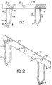
- FIGURE 1 is a front view of a metal strip of stamped and formed U-shaped, contacts joined together by a common, removable carrier strip, as used in the method of this invention.
- FIGURE 2 is a perspective view thereof.
- FIGURE 3 is a front view of a pair of the metal strips of Figure 1 arranged in a back-to-back relationship.
- FIGURE 4 is a perspective view of a pair of the metal strips, as shown in Figure 3, further showing the closed ends of the contacts insert molded within a dielectric body.
- FIGURE 5 is a front view of a single shorting bar, with carrier strips removed, as produced by the method hereof.
- FIGURE 6 is a side view of the shorting bar of Figure 5, taken along line 6-6.
- FIGURE 7 is perspective view of the shorting bar of Figures 5 and 6.
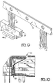
- FIGURE 8 is a front view similar to Figure 3, showing an alternate embodiment, further showing an insert molded dielectric body about the closed ends of one set of contacts.
- FIGURE 9 is a perspective view thereof.
- FIGURE 10 is a simplified sectional view of a modular jack housing into which the shorting bar of Figure 5 has been placed.
- This invention is directed to a method of manufacturing a shorting bar insert for placement in a modular jack assembly to provide for the selective shorting of predetermined contacts, i.e. maintain line continuity, during periods of nonelectrical engagement with a modular plug.
- a modular jack and plug connector to which this invention relates include spring beam or cantilevered contacts, anchored in the housing and protruding from a portion of the jack housing into the plug receiving cavity of the jack, the contacts or terminals being separated from each other by molded ribs in the housing jack.
- the terminals include terminal portions, usually in the form of terminal pins.
- the terminal pins may form solder tails for insertion into holes in a printed circuit board.
- the terminal pins or solder tails are arranged in a single row, and in many other instances the terminal pins or solder tails are arranged in two rows.
- the cantilevered contacts extend into the cavity so that the contact arms will be resiliently engaged by respective contacts of a complementary plug when inserted into the cavity.
- an effective shorting bar for each selected pair of contact arms is required.
- the present invention provides for a method of producing a shorting bar insert in a simple, yet effective manner.
- a plurality of stamped and formed U-shaped contacts 10, joined to a common carrier strip 12 are provided.
- the contacts are characterized by a pair of parallel legs 14 running from the carrier strip 12, to a looped or closed end 16.
- flat surfaces 18 are included, which as hereinafter explained, are positioned between molding pins to maintain contact spacing during the insert molding operation.
- the carrier strip 12 is provided with plural registration means 20, preferably in the form of pilot holes, where such registration means are laterally offset from the centerline of the parallel legs 14, see Figure 1.
- each contact is offset 22 one half material thickness toward the rear face 27 of the carrier strip 12, and the tip or joined end 16 is offset toward the front face 24 to provide crossover clearance.
- a selected portion 28 of legs 14 may be selectively plated with a conductive material, such as gold, by a plating practice as known in the art.
- ribs 30 may be formed along the contact surface 32, where such ribs occupy non-shorted contact positions laterally spaced from the legs 14.
- a pair of side barbs 34 may be provided so as to latch the unit within a corresponding slot, not shown in the modular jack housing.
- Figures 8 and 9 illustrate a modified embodiment for the shorting bar insert of this invention.
- one of the legs 14' remains straight while the other arm is angled to meet at the junction 18', representing the flat surface for the molding spacer, as discussed above.
- the modular unit 29' has been modified to include shoulder portion 40, projecting from a side wall 42 thereof. Note also that no ribs are provided to occupy the non-shorted contact positions.
- the shorting bar insert of the first embodiment is intended to be bottom loaded into the modular jack assembly, the latter embodiment is intended to be rear loaded. In either case, the shorting bar insert functions in an identical manner.
- Figure 10 is a sectional view of a modular jack assembly 44, illustrating the cantilevered contact arms 46, mounted therewithin as known in the art, and the modular unit 29 positioned to provide selective shorting of contacts.
Landscapes
- Engineering & Computer Science (AREA)
- Manufacturing & Machinery (AREA)
- Manufacturing Of Electrical Connectors (AREA)
- Coupling Device And Connection With Printed Circuit (AREA)
Applications Claiming Priority (2)
| Application Number | Priority Date | Filing Date | Title |
|---|---|---|---|
| US08/048,097 US5274918A (en) | 1993-04-15 | 1993-04-15 | Method for producing contact shorting bar insert for modular jack assembly |
| US48097 | 1993-04-15 |
Publications (2)
| Publication Number | Publication Date |
|---|---|
| EP0620619A2 true EP0620619A2 (fr) | 1994-10-19 |
| EP0620619A3 EP0620619A3 (en) | 1995-11-02 |
Family
ID=21952711
Family Applications (1)
| Application Number | Title | Priority Date | Filing Date |
|---|---|---|---|
| EP94302472A Withdrawn EP0620619A3 (en) | 1993-04-15 | 1994-04-07 | Method for producing contact shorting bar insert for modular jack assembly. |
Country Status (2)
| Country | Link |
|---|---|
| US (1) | US5274918A (fr) |
| EP (1) | EP0620619A3 (fr) |
Cited By (1)
| Publication number | Priority date | Publication date | Assignee | Title |
|---|---|---|---|---|
| DE202019104687U1 (de) * | 2019-08-27 | 2020-12-01 | Wago Verwaltungsgesellschaft Mbh | Querverbinder |
Families Citing this family (98)
| Publication number | Priority date | Publication date | Assignee | Title |
|---|---|---|---|---|
| JP2734851B2 (ja) * | 1991-12-19 | 1998-04-02 | 住友電装株式会社 | 摩耗検知用プローブの製造方法 |
| US5359761A (en) * | 1993-09-09 | 1994-11-01 | Delco Electronics Corp. | Method of making a header or housing for electrical connection to a hybrid circuit including an in-cavity trim of a terminal frame |
| US5593314A (en) * | 1995-01-31 | 1997-01-14 | The Whitaker Corporation | Staggered terminal array for mod plug |
| DE19514864A1 (de) * | 1995-04-27 | 1996-11-07 | Duerrwaechter E Dr Doduco | Kurzschlußsicherung für elektrische Zünder von Airbags |
| FR2737941A1 (fr) * | 1995-08-18 | 1997-02-21 | Amp France | Assemblage de jack modulaire electrique |
| JP3339300B2 (ja) * | 1996-04-23 | 2002-10-28 | 矢崎総業株式会社 | コネクタの製造方法 |
| EP0845838A3 (fr) * | 1996-11-28 | 1999-05-12 | The Whitaker Corporation | Connecteur électrique |
| FR2760592B1 (fr) * | 1997-03-10 | 2006-04-21 | Schneider Electric Sa | Additif de cablage d'appareils electriques polyphases |
| JPH11251006A (ja) * | 1997-12-19 | 1999-09-17 | Osram Sylvania Inc | リードフレーム、リードフレームアセンブリ及び関連方法 |
| JPH11185926A (ja) * | 1997-12-25 | 1999-07-09 | Yazaki Corp | コネクタ、コネクタの製造方法及びこの製造方法に用いられる型構造 |
| US6162076A (en) * | 1998-08-28 | 2000-12-19 | Senior Industries, Inc. | Electrical shorting assembly for electrical jacks and the like |
| JP3081835B1 (ja) * | 1999-03-30 | 2000-08-28 | 株式会社明王化成 | 電子回路コネクタ端子のインサート成形方法 |
| US6869292B2 (en) * | 2001-07-31 | 2005-03-22 | Fci Americas Technology, Inc. | Modular mezzanine connector |
| EP2451026A3 (fr) * | 2001-11-14 | 2013-04-03 | Fci | Réduction de la diaphonie pour connecteurs électriques |
| US6981883B2 (en) * | 2001-11-14 | 2006-01-03 | Fci Americas Technology, Inc. | Impedance control in electrical connectors |
| US6994569B2 (en) | 2001-11-14 | 2006-02-07 | Fci America Technology, Inc. | Electrical connectors having contacts that may be selectively designated as either signal or ground contacts |
| US20050196987A1 (en) * | 2001-11-14 | 2005-09-08 | Shuey Joseph B. | High density, low noise, high speed mezzanine connector |
| US6652318B1 (en) | 2002-05-24 | 2003-11-25 | Fci Americas Technology, Inc. | Cross-talk canceling technique for high speed electrical connectors |
| US7390200B2 (en) | 2001-11-14 | 2008-06-24 | Fci Americas Technology, Inc. | High speed differential transmission structures without grounds |
| US7008250B2 (en) * | 2002-08-30 | 2006-03-07 | Fci Americas Technology, Inc. | Connector receptacle having a short beam and long wipe dual beam contact |
| US6899548B2 (en) * | 2002-08-30 | 2005-05-31 | Fci Americas Technology, Inc. | Electrical connector having a cored contact assembly |
| US7270573B2 (en) * | 2002-08-30 | 2007-09-18 | Fci Americas Technology, Inc. | Electrical connector with load bearing features |
| US20040147169A1 (en) | 2003-01-28 | 2004-07-29 | Allison Jeffrey W. | Power connector with safety feature |
| US7018246B2 (en) * | 2003-03-14 | 2006-03-28 | Fci Americas Technology, Inc. | Maintenance of uniform impedance profiles between adjacent contacts in high speed grid array connectors |
| US7083432B2 (en) * | 2003-08-06 | 2006-08-01 | Fci Americas Technology, Inc. | Retention member for connector system |
| US7517250B2 (en) * | 2003-09-26 | 2009-04-14 | Fci Americas Technology, Inc. | Impedance mating interface for electrical connectors |
| US7524209B2 (en) | 2003-09-26 | 2009-04-28 | Fci Americas Technology, Inc. | Impedance mating interface for electrical connectors |
| CN101882718B (zh) | 2003-12-31 | 2012-11-21 | Fci公司 | 电源触头及包括电源触头的连接器 |
| US7458839B2 (en) * | 2006-02-21 | 2008-12-02 | Fci Americas Technology, Inc. | Electrical connectors having power contacts with alignment and/or restraining features |
| US7242325B2 (en) * | 2004-08-02 | 2007-07-10 | Sony Corporation | Error correction compensating ones or zeros string suppression |
| US7160117B2 (en) * | 2004-08-13 | 2007-01-09 | Fci Americas Technology, Inc. | High speed, high signal integrity electrical connectors |
| US7214104B2 (en) * | 2004-09-14 | 2007-05-08 | Fci Americas Technology, Inc. | Ball grid array connector |
| US7281950B2 (en) * | 2004-09-29 | 2007-10-16 | Fci Americas Technology, Inc. | High speed connectors that minimize signal skew and crosstalk |
| US7476108B2 (en) * | 2004-12-22 | 2009-01-13 | Fci Americas Technology, Inc. | Electrical power connectors with cooling features |
| US7226296B2 (en) * | 2004-12-23 | 2007-06-05 | Fci Americas Technology, Inc. | Ball grid array contacts with spring action |
| US7384289B2 (en) * | 2005-01-31 | 2008-06-10 | Fci Americas Technology, Inc. | Surface-mount connector |
| US7303427B2 (en) * | 2005-04-05 | 2007-12-04 | Fci Americas Technology, Inc. | Electrical connector with air-circulation features |
| US20060228912A1 (en) * | 2005-04-07 | 2006-10-12 | Fci Americas Technology, Inc. | Orthogonal backplane connector |
| US20060245137A1 (en) * | 2005-04-29 | 2006-11-02 | Fci Americas Technology, Inc. | Backplane connectors |
| US7396259B2 (en) * | 2005-06-29 | 2008-07-08 | Fci Americas Technology, Inc. | Electrical connector housing alignment feature |
| US7819708B2 (en) * | 2005-11-21 | 2010-10-26 | Fci Americas Technology, Inc. | Receptacle contact for improved mating characteristics |
| US7425145B2 (en) * | 2006-05-26 | 2008-09-16 | Fci Americas Technology, Inc. | Connectors and contacts for transmitting electrical power |
| US7726982B2 (en) * | 2006-06-15 | 2010-06-01 | Fci Americas Technology, Inc. | Electrical connectors with air-circulation features |
| US7462924B2 (en) * | 2006-06-27 | 2008-12-09 | Fci Americas Technology, Inc. | Electrical connector with elongated ground contacts |
| US8142236B2 (en) * | 2006-08-02 | 2012-03-27 | Tyco Electronics Corporation | Electrical connector having improved density and routing characteristics and related methods |
| US7753742B2 (en) * | 2006-08-02 | 2010-07-13 | Tyco Electronics Corporation | Electrical terminal having improved insertion characteristics and electrical connector for use therewith |
| US7549897B2 (en) * | 2006-08-02 | 2009-06-23 | Tyco Electronics Corporation | Electrical connector having improved terminal configuration |
| US7670196B2 (en) * | 2006-08-02 | 2010-03-02 | Tyco Electronics Corporation | Electrical terminal having tactile feedback tip and electrical connector for use therewith |
| US7591655B2 (en) * | 2006-08-02 | 2009-09-22 | Tyco Electronics Corporation | Electrical connector having improved electrical characteristics |
| US7500871B2 (en) * | 2006-08-21 | 2009-03-10 | Fci Americas Technology, Inc. | Electrical connector system with jogged contact tails |
| US7713088B2 (en) | 2006-10-05 | 2010-05-11 | Fci | Broadside-coupled signal pair configurations for electrical connectors |
| US7708569B2 (en) | 2006-10-30 | 2010-05-04 | Fci Americas Technology, Inc. | Broadside-coupled signal pair configurations for electrical connectors |
| US7497736B2 (en) * | 2006-12-19 | 2009-03-03 | Fci Americas Technology, Inc. | Shieldless, high-speed, low-cross-talk electrical connector |
| US20080203547A1 (en) * | 2007-02-26 | 2008-08-28 | Minich Steven E | Insert molded leadframe assembly |
| US7422444B1 (en) * | 2007-02-28 | 2008-09-09 | Fci Americas Technology, Inc. | Orthogonal header |
| US7641500B2 (en) * | 2007-04-04 | 2010-01-05 | Fci Americas Technology, Inc. | Power cable connector system |
| US7905731B2 (en) * | 2007-05-21 | 2011-03-15 | Fci Americas Technology, Inc. | Electrical connector with stress-distribution features |
| US7811100B2 (en) * | 2007-07-13 | 2010-10-12 | Fci Americas Technology, Inc. | Electrical connector system having a continuous ground at the mating interface thereof |
| US7762857B2 (en) | 2007-10-01 | 2010-07-27 | Fci Americas Technology, Inc. | Power connectors with contact-retention features |
| US8764464B2 (en) * | 2008-02-29 | 2014-07-01 | Fci Americas Technology Llc | Cross talk reduction for high speed electrical connectors |
| US8062051B2 (en) * | 2008-07-29 | 2011-11-22 | Fci Americas Technology Llc | Electrical communication system having latching and strain relief features |
| US8545240B2 (en) | 2008-11-14 | 2013-10-01 | Molex Incorporated | Connector with terminals forming differential pairs |
| MY155071A (en) | 2008-12-12 | 2015-08-28 | Molex Inc | Resonance modifying connector |
| USD606497S1 (en) | 2009-01-16 | 2009-12-22 | Fci Americas Technology, Inc. | Vertical electrical connector |
| USD606496S1 (en) | 2009-01-16 | 2009-12-22 | Fci Americas Technology, Inc. | Right-angle electrical connector |
| USD640637S1 (en) | 2009-01-16 | 2011-06-28 | Fci Americas Technology Llc | Vertical electrical connector |
| USD608293S1 (en) | 2009-01-16 | 2010-01-19 | Fci Americas Technology, Inc. | Vertical electrical connector |
| USD610548S1 (en) | 2009-01-16 | 2010-02-23 | Fci Americas Technology, Inc. | Right-angle electrical connector |
| USD664096S1 (en) | 2009-01-16 | 2012-07-24 | Fci Americas Technology Llc | Vertical electrical connector |
| US8323049B2 (en) * | 2009-01-30 | 2012-12-04 | Fci Americas Technology Llc | Electrical connector having power contacts |
| USD619099S1 (en) | 2009-01-30 | 2010-07-06 | Fci Americas Technology, Inc. | Electrical connector |
| US9277649B2 (en) | 2009-02-26 | 2016-03-01 | Fci Americas Technology Llc | Cross talk reduction for high-speed electrical connectors |
| US8366485B2 (en) | 2009-03-19 | 2013-02-05 | Fci Americas Technology Llc | Electrical connector having ribbed ground plate |
| USD618181S1 (en) | 2009-04-03 | 2010-06-22 | Fci Americas Technology, Inc. | Asymmetrical electrical connector |
| USD618180S1 (en) | 2009-04-03 | 2010-06-22 | Fci Americas Technology, Inc. | Asymmetrical electrical connector |
| US8608510B2 (en) * | 2009-07-24 | 2013-12-17 | Fci Americas Technology Llc | Dual impedance electrical connector |
| US8267721B2 (en) * | 2009-10-28 | 2012-09-18 | Fci Americas Technology Llc | Electrical connector having ground plates and ground coupling bar |
| US8616919B2 (en) * | 2009-11-13 | 2013-12-31 | Fci Americas Technology Llc | Attachment system for electrical connector |
| CN102725919B (zh) * | 2009-12-30 | 2015-07-08 | Fci公司 | 具有阻抗调节肋的电连接器 |
| US9136634B2 (en) | 2010-09-03 | 2015-09-15 | Fci Americas Technology Llc | Low-cross-talk electrical connector |
| US8616915B2 (en) * | 2011-05-02 | 2013-12-31 | Apple Inc. | Wire-free, unibody jumper |
| JP5813488B2 (ja) * | 2011-12-09 | 2015-11-17 | 日本航空電子工業株式会社 | コネクタの製造方法 |
| EP2624034A1 (fr) | 2012-01-31 | 2013-08-07 | Fci | Dispositif de couplage optique démontable |
| USD727852S1 (en) | 2012-04-13 | 2015-04-28 | Fci Americas Technology Llc | Ground shield for a right angle electrical connector |
| USD727268S1 (en) | 2012-04-13 | 2015-04-21 | Fci Americas Technology Llc | Vertical electrical connector |
| US9257778B2 (en) | 2012-04-13 | 2016-02-09 | Fci Americas Technology | High speed electrical connector |
| USD718253S1 (en) | 2012-04-13 | 2014-11-25 | Fci Americas Technology Llc | Electrical cable connector |
| US8944831B2 (en) | 2012-04-13 | 2015-02-03 | Fci Americas Technology Llc | Electrical connector having ribbed ground plate with engagement members |
| US9543703B2 (en) | 2012-07-11 | 2017-01-10 | Fci Americas Technology Llc | Electrical connector with reduced stack height |
| USD751507S1 (en) | 2012-07-11 | 2016-03-15 | Fci Americas Technology Llc | Electrical connector |
| USD745852S1 (en) | 2013-01-25 | 2015-12-22 | Fci Americas Technology Llc | Electrical connector |
| USD720698S1 (en) | 2013-03-15 | 2015-01-06 | Fci Americas Technology Llc | Electrical cable connector |
| US8979577B2 (en) * | 2013-06-24 | 2015-03-17 | Dinkle Enterprise Co., Ltd. | Bridging terminal |
| USD795199S1 (en) * | 2014-03-25 | 2017-08-22 | Molex, Llc | Retainer for electric connector |
| US9331448B2 (en) * | 2014-03-25 | 2016-05-03 | Tyco Electronics Corporation | Electrical connector having primary and secondary leadframes |
| JP1558906S (fr) * | 2016-02-29 | 2016-09-20 | ||
| JP1558907S (fr) * | 2016-02-29 | 2016-09-20 | ||
| US12191593B2 (en) * | 2022-08-29 | 2025-01-07 | Dinkle Enterprise Co., Ltd. | Jumper terminal belt structure |
Family Cites Families (10)
| Publication number | Priority date | Publication date | Assignee | Title |
|---|---|---|---|---|
| US4274691A (en) * | 1978-12-05 | 1981-06-23 | Amp Incorporated | Modular jack |
| US4552423A (en) * | 1984-03-30 | 1985-11-12 | Amp Incorporated | Shunted electrical connectors |
| US4671599A (en) * | 1984-10-30 | 1987-06-09 | Amp Incorporated | Shielded electrical connector |
| US4699443A (en) * | 1984-12-28 | 1987-10-13 | American Telephone And Telegraph Company | Modular telephone jack |
| GB8600831D0 (en) * | 1986-01-15 | 1986-02-19 | Amp Italia | Modular jack |
| JPS6460929A (en) * | 1987-09-01 | 1989-03-08 | Nihon Kaiheiki Ind Co Ltd | Manufacture of switch base |
| JPH01102827A (ja) * | 1987-10-14 | 1989-04-20 | Fuji Electric Co Ltd | 電磁リレーの接点ばね装置の製造方法 |
| US4863393A (en) * | 1988-05-25 | 1989-09-05 | Keptel, Inc. | Modular jack assembly with improved bridging arrangement |
| US5123854A (en) * | 1991-03-13 | 1992-06-23 | Molex Incorporated | Shunted electrical connector |
| US5178563A (en) * | 1992-05-12 | 1993-01-12 | Amp Incorporated | Contact assembly and method for making same |
-
1993
- 1993-04-15 US US08/048,097 patent/US5274918A/en not_active Expired - Lifetime
-
1994
- 1994-04-07 EP EP94302472A patent/EP0620619A3/en not_active Withdrawn
Cited By (1)
| Publication number | Priority date | Publication date | Assignee | Title |
|---|---|---|---|---|
| DE202019104687U1 (de) * | 2019-08-27 | 2020-12-01 | Wago Verwaltungsgesellschaft Mbh | Querverbinder |
Also Published As
| Publication number | Publication date |
|---|---|
| US5274918A (en) | 1994-01-04 |
| EP0620619A3 (en) | 1995-11-02 |
Similar Documents
| Publication | Publication Date | Title |
|---|---|---|
| US5274918A (en) | Method for producing contact shorting bar insert for modular jack assembly | |
| US5123854A (en) | Shunted electrical connector | |
| US5277596A (en) | Method of producing a card edge mounted connector and the resulting assembly thereof | |
| EP0452061B1 (fr) | Connecteur électrique à plusieurs conducteurs ayant des contacts étampés et formés | |
| US4322120A (en) | Plug-in connector with improved spring contact | |
| US6041498A (en) | Method of making a contact assembly | |
| US4842528A (en) | Solder post retention means | |
| EP0354676B1 (fr) | Procédé de fabrication d'un assemblage de fusibles | |
| US5324213A (en) | Ballast connector | |
| US4580868A (en) | Keying system for electrical connectors | |
| US4607899A (en) | Shunt connector and method of forming | |
| EP0585731B1 (fr) | Block de connexion | |
| EP0717468B1 (fr) | Connecteur interrompant d'abord les contacts polaires et après le contact à la terre | |
| CA1130878A (fr) | Connecteur auto-denudant pour cable en nappe | |
| US5078611A (en) | Electrical connector and electric contact therefor | |
| US4948376A (en) | Connector | |
| US4708416A (en) | Electrical connecting terminal for a connector | |
| US4072379A (en) | Electric power distributing apparatus | |
| EP0654865B1 (fr) | Connecteur électrique à dispositif de shuntage | |
| US4758168A (en) | Contact device composed of a plug and a corresponding socket | |
| US5061203A (en) | Magnetic ballast connector system | |
| US4583640A (en) | Packaging arrangement for electrical connectors | |
| US4331376A (en) | Electric connectors | |
| EP0109297B1 (fr) | Eléments de contacts électriques et d'assemblages de connecteurs électriques | |
| CA2054656A1 (fr) | Prise murale et contact connexe |
Legal Events
| Date | Code | Title | Description |
|---|---|---|---|
| PUAI | Public reference made under article 153(3) epc to a published international application that has entered the european phase |
Free format text: ORIGINAL CODE: 0009012 |
|
| AK | Designated contracting states |
Kind code of ref document: A2 Designated state(s): CH DE FR GB IT LI NL SE |
|
| PUAL | Search report despatched |
Free format text: ORIGINAL CODE: 0009013 |
|
| AK | Designated contracting states |
Kind code of ref document: A3 Designated state(s): CH DE FR GB IT LI NL SE |
|
| STAA | Information on the status of an ep patent application or granted ep patent |
Free format text: STATUS: THE APPLICATION IS DEEMED TO BE WITHDRAWN |
|
| 18D | Application deemed to be withdrawn |
Effective date: 19960503 |