EP0620699B1 - Détecteur de mouvement - Google Patents
Détecteur de mouvement Download PDFInfo
- Publication number
- EP0620699B1 EP0620699B1 EP94105421A EP94105421A EP0620699B1 EP 0620699 B1 EP0620699 B1 EP 0620699B1 EP 94105421 A EP94105421 A EP 94105421A EP 94105421 A EP94105421 A EP 94105421A EP 0620699 B1 EP0620699 B1 EP 0620699B1
- Authority
- EP
- European Patent Office
- Prior art keywords
- evaluation circuit
- input
- current
- motion detector
- calendar
- Prior art date
- Legal status (The legal status is an assumption and is not a legal conclusion. Google has not performed a legal analysis and makes no representation as to the accuracy of the status listed.)
- Expired - Lifetime
Links
- 238000011156 evaluation Methods 0.000 claims description 41
- 230000006870 function Effects 0.000 claims description 6
- 241000112598 Pseudoblennius percoides Species 0.000 claims description 4
- 230000001419 dependent effect Effects 0.000 claims description 4
- 238000012544 monitoring process Methods 0.000 claims 3
- 230000004913 activation Effects 0.000 description 10
- 238000009434 installation Methods 0.000 description 6
- 230000003203 everyday effect Effects 0.000 description 1
Images

Classifications
-
- H—ELECTRICITY
- H05—ELECTRIC TECHNIQUES NOT OTHERWISE PROVIDED FOR
- H05B—ELECTRIC HEATING; ELECTRIC LIGHT SOURCES NOT OTHERWISE PROVIDED FOR; CIRCUIT ARRANGEMENTS FOR ELECTRIC LIGHT SOURCES, IN GENERAL
- H05B47/00—Circuit arrangements for operating light sources in general, i.e. where the type of light source is not relevant
- H05B47/10—Controlling the light source
- H05B47/16—Controlling the light source by timing means
-
- H—ELECTRICITY
- H05—ELECTRIC TECHNIQUES NOT OTHERWISE PROVIDED FOR
- H05B—ELECTRIC HEATING; ELECTRIC LIGHT SOURCES NOT OTHERWISE PROVIDED FOR; CIRCUIT ARRANGEMENTS FOR ELECTRIC LIGHT SOURCES, IN GENERAL
- H05B47/00—Circuit arrangements for operating light sources in general, i.e. where the type of light source is not relevant
- H05B47/10—Controlling the light source
- H05B47/105—Controlling the light source in response to determined parameters
- H05B47/115—Controlling the light source in response to determined parameters by determining the presence or movement of objects or living beings
-
- Y—GENERAL TAGGING OF NEW TECHNOLOGICAL DEVELOPMENTS; GENERAL TAGGING OF CROSS-SECTIONAL TECHNOLOGIES SPANNING OVER SEVERAL SECTIONS OF THE IPC; TECHNICAL SUBJECTS COVERED BY FORMER USPC CROSS-REFERENCE ART COLLECTIONS [XRACs] AND DIGESTS
- Y02—TECHNOLOGIES OR APPLICATIONS FOR MITIGATION OR ADAPTATION AGAINST CLIMATE CHANGE
- Y02B—CLIMATE CHANGE MITIGATION TECHNOLOGIES RELATED TO BUILDINGS, e.g. HOUSING, HOUSE APPLIANCES OR RELATED END-USER APPLICATIONS
- Y02B20/00—Energy efficient lighting technologies, e.g. halogen lamps or gas discharge lamps
- Y02B20/40—Control techniques providing energy savings, e.g. smart controller or presence detection
Definitions
- the invention relates to a motion detector motion-dependent switching of at least one light source.
- a motion detector for motion-dependent Switch at least one of the at least a light source, if necessary, with an energy supply level connecting switching stage known, depending the signals of a motion detector can be controlled.
- Motion detector for switching light depending on motion usually have a light sensor that the switching output below a set threshold (lower brightness limit) releases at dusk. It is a disadvantage that this light sensor also detects external light from street lamps, Car headlights, flashlights or even through the switched light itself reacts and thus the device pretends an incorrect (too high) brightness and possibly prevents switching when moving. Besides, is the setting of the lower brightness limit for Installation time (daytime) not possible because of it is too bright. An adjustment to the correct working point can take several days because the result is always on can be checked next day. The setting at one recommended mounting height of 2.5 m and more difficult additionally the adjustment work.
- the invention has for its object a motion detector of the type mentioned at the beginning, which the difficult setting of brightness values not required and that also in the presence of extraneous light, such as street lamp light, Car headlight and flashlight reliable allows switching when moving.
- a motion detector makes this task dependent on motion Switching at least one light source solved, with one of the at least one light source as needed connecting with an energy supply level Switching stage that depends on the signals of a motion sensor can be controlled as soon as the current light intensity falls below a predeterminable lower brightness limit, where the current light intensity by a Time module according to the sunrise and sunset defined position of the sun depending on the current calendar day and the current calendar month the time module is an evaluation circuit with read-only memory which has the sunrises and sunsets depending on the calendar day and the calendar month are stored, the evaluation circuit with read-only memory the current calendar day and the current calendar month can be specified, the evaluation circuit the light source depending on the current Considering sunrise and sunset controlled by predetermined difference times and an AND gate it is provided that the switching stage of the output side Controls light source, the first input of which with a Motion sensor controlled switching stage is connected and its second input to one of the evaluation circuit controlled switching stage is connected, the latter during guard operation by means of the evaluation circuit is closed.
- the advantages that can be achieved with the invention are in particular in that controlled by a motion sensor no need-oriented lighting operation External light, not even from the motion detector itself switched light source is disturbed.
- the time range in whom the guardian should work (be active) can already exact, unambiguous at the time of installation during the day and reliably reproducible regardless of who during the installation of random lighting conditions can be set. A review of the setting made and can readjust the following day omitted.
- This function is achieved in that the release time the motion sensor from a timer (clock and calendar or radio receiver clock) is derived, its set Current value according to the date (sunrise and sunset) changes. These times of sunrise and can be stored in a read-only memory.
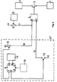
- FIG. 1 is an embodiment with clockwork and calendar shown.
- a light source 1 can be seen which via a switching stage 2 with a power supply stage 3, e.g. a network.
- Switching stage 2 is controlled by an AND gate 4.
- a motion sensor with evaluation level 5 e.g. an infrared detector
- a switching stage 6 which in the closed Status of the logic signal H (high) via a signal line 7 switches through to the input a of the AND gate 4.
- An evaluation circuit 8 with read-only memory 8 are times of the day depending on the calendar day and month Saved sunrises and sunsets.
- To the first input a of the evaluation circuit 8 with read-only memory is a clockwork 9 and a calendar movement at the second input b 10 connected.
- the third input c of the evaluation circuit 8 with read-only memory receives signals one Differential value memory 11, while the first output d the evaluation circuit 8 with read-only memory the first Input a of this memory 11 receives signals.
- the second input b of the differential value memory 11 is connected an input device 12 connected to the input of for programming the motion detector important data serves the installation.
- the second output e of the evaluation circuit 8 with read-only memory controls a switching stage 13 on.
- a third output f of the evaluation circuit 8 is used to control a further switching stage 15.
- time module 17 The arrangement consisting of components 8 to 13 and 15 is also referred to as time module 17.
- the mode of operation of the arrangement is described in more detail below.
- the motion detector is not activated, because of the sufficient current daylight a demand-driven one controlled by the motion sensor Lighting operation is not required.
- the Switch stage 13 is open, causing the AND gate 4 due of the missing signal H at its input b Switching stage 2 always keeps open - regardless of the Switching states of the other switching stages 6 and 15.
- the Light source 1 is never on the motion detector switched on.
- the second activation state is the motion detector activated (watchdog mode) because of the current daytime brightness is no longer sufficient and one controlled by the motion sensor needs-based lighting is required.
- the switching stage 13 is closed and at the input b of the AND gate 4, the signal H is present. Detects the motion sensor 5 a movement during the second activation state, so he closes switching stage 6, which also a signal H is applied to the input a of the AND gate 4 and the AND gate 4 consequently closes the switching stage 2.
- the light source 1 is thus switched on as required.
- the third activation state is the current daytime brightness is also no longer sufficient.
- Switching stage 13 is closed.
- the signal H is present.
- the Switching stage 15 closed by the evaluation circuit 8, whereby the signal H to the input a of the AND gate 4th is activated.
- the AND gate 4 closes the Switching stage 2, whereby the light source is switched on continuously remains (continuous light operation) - regardless of need-oriented Switching operations of the motion sensor 5. Only after Opening of the switching stage 15 by the evaluation circuit 8 operation goes into that controlled by the motion sensor needs-based lighting operation accordingly the second activation state explained above about.
- time module 17 expediently as its own, in the motion detector insertable unit formed.
- the one for programming required controls of the input device 12 and the display of day, month and time are built in Condition covered and not accessible. In this way becomes an intentional or unintentional adjustment prevented.
- the Evaluation circuit 8 a read-only memory in which the Times of the sunrises SA and sunsets SU for are filed every calendar day.
- the calendar 10 activated by means of suitable signals which are stored in this read-only memory stored data, while the clockwork 9 time coordination of the timing element 17 and in particular the time correct control of the switching stages 13, 15 accomplished.
- the difference D1 A - SA between the entered time 6:00 a.m. and sunrise 6:32 a.m. is -32 minutes in the morning.
- the difference D2 U - SU between the entered time 7:00 p.m. and sunset 6:30 p.m. is +30 minutes in the evening.
- the differences D1, D2 are stored by the difference value memory 11.
- the output e of the evaluation circuit 8 is released day after day depending on the sunrise and sunset values SA, SU stored in the read-only memory of the evaluation circuit 8, ie the calendar 10 is activated the sunrise and sunset values SA, SU corresponding to the current date, these values are given via output d of the evaluation circuit 8 to input a of the differential value memory 11 and summed there with D1 and D2.
- the total values SA + D1 and SU + D2 are given back to input c of the evaluation circuit 8, which in conjunction with the current time reported by the clockwork 9 at input a of the evaluation circuit 8 leads to the correct release of the output e of the evaluation circuit 8.
- the release times of the watchdog operation are not every day, but for example every third day (every fifth day, every tenth day etc.) according to the changed Times of sunrise and sunset to correct and update. This will save space saved, i.e. the read-only memory of the evaluation circuit 8 may be of lower capacity.
- guard operation / continuous light operation serve depending on the sunset SU changing times to set the SU + D2 Start of continuous light operation, e.g. a shop window to illuminate.
- start of continuous light operation e.g. a shop window to illuminate.
- the values DE and DA are also the evaluation circuit 8 via the input device 12 when installing the motion detector entered.
- switching stages 13 and 15 controlled via the outputs e and f of the evaluation circuit 8, i.e. closed.
- DE to SA + D1 Guardian operation
- switching stage 13 is via the output e of the evaluation circuit 8 is driven, i.e. closed.
- FIG 2 is an embodiment with a radio clock receiver shown.
- clockwork 9 and calendar work are omitted 10, difference value memory 11 and input device 12.
- the inputs a and b of the evaluation circuit 8 are with a radio-controlled clock receiver 18 which stores the current calendar day, the current calendar month and the current Receives the time and specifies the evaluation circuit 8.
- the time and date must be Installation of the motion detector cannot be entered. keyboard and display and, if necessary, a power failure protection can be omitted.
- the differences D1, D2 - e.g. +30 min./30 min. - can either be fixed or by means of an optional multi-stage selector switch (Code switch) 19 in pre-programmed steps - e.g. ⁇ 15 min., ⁇ 45 min. - to be selected during installation.
- time module 17 according to FIG. 2, there is the time module 17 'accordingly from components 8, 13, 15, 18 and 19.
Landscapes
- Circuit Arrangement For Electric Light Sources In General (AREA)
- Burglar Alarm Systems (AREA)
- Vehicle Body Suspensions (AREA)
- Eye Examination Apparatus (AREA)
- Measurement Of The Respiration, Hearing Ability, Form, And Blood Characteristics Of Living Organisms (AREA)
Claims (8)
- Détecteur de mouvement pour la commutation, en fonction d'un mouvement d'au moins une source de lumière, comprenant un étage de commutation (2) qui relie selon le besoin ladite au moins une source de lumière (1) à un étage d'alimentation en énergie (3) et qui peut être commandé en fonction des signaux d'un capteur de mouvement (5) dès que l'intensité de lumière du moment descend en dessous d'une limite de clarté inférieure qui peut être donnée au préalable, dans lequel l'intensité de lumière du moment est reproduite par un module horaire (17, 17') suivant l'état du soleil, déterminé par le lever du soleil et le coucher du soleil, en fonction du jour de calendrier du moment et du mois de calendrier du moment, dans lequel le module horaire (17, 17') présente un circuit d'évaluation (8) comprenant une mémoire de valeurs fixes dans laquelle sont mémorisés les levers de soleil et couchers de soleil en fonction du jour de calendrier et du mois de calendrier, dans lequel le jour de calendrier du moment et le mois de calendrier du moment sont donnés au préalable, du côté de l'entrée, au circuit d'évaluation (8) comprenant la mémoire de valeurs fixes, dans lequel le circuit d'évaluation (8) commande la source de lumière en fonction des lever du soleil et coucher du soleil du moment en prenant en considération des durées de différences (D1, D2) données au préalable, et dans lequel il est prévu une porte ET (4) qui commande, du côté de la sortie, l'étage de commutation (2), de la source de lumière (1), dont la première sortie (a) est reliée à un étage de commutation (6) commandé par le capteur de mouvement (5) et dont la seconde entrée (b) est raccordée à un étage de commutation (13) commandé par le circuit d'évaluation (8), ce dernier étage (13) étant fermé au moyen du circuit d'évaluation (8) pendant le fonctionnement en dispositif de contrôle.
- Détecteur de mouvement suivant la revendication 1, caractérisé en ce qu'un système de calendrier (10) et un système d'horloge (9) sont raccordés au circuit d'évaluation (8) comportant la mémoire de valeurs fixes.
- Détecteur de mouvement suivant la revendication 1, caractérisé en ce qu'un récepteur d'horloge par radio (18) est raccordé au circuit d'évaluation (8) comportant la mémoire de valeurs fixes.
- Détecteur de mouvement suivant l'une des revendications 1 et 2, caractérisé en ce qu'un dispositif d'introduction (12) sert à l'introduction de données.
- Détecteur de mouvement suivant l'une des revendications 1 et 3, caractérisé en ce qu'un commutateur de présélection (19) sert à l'introduction de données.
- Détecteur de mouvement suivant l'une des revendications 1 à 5, caractérisé en ce qu'une mémoire de valeurs différentielles (11) forme et mémorise les durées de différences (D1, D2) entre une fin introduite du fonctionnement en dispositif de contrôle (a) et un lever de soleil (SA) du moment ainsi qu'entre un commencement introduit du fonctionnement en dispositif de contrôle (U) et le coucher du soleil (SU) du moment.
- Détecteur de mouvement suivant l'une des revendications 1 à 6, caractérisé en ce que des données supplémentaires pour un fonctionnement à allumage ininterrompu de la source de lumière peuvent être introduites, le commencement du fonctionnement à allumage ininterrompu étant déterminé en fonction du coucher de soleil du moment, en prenant en considération une durée de différences prédéterminée en provenance du circuit d'évaluation (8).
- Détecteur de mouvement suivant la revendication 7, caractérisé en ce que la première entrée (a) de la porte ET (4) est raccordée en plus à un autre étage de commutation (15) commandé également par le circuit d'évaluation (8), ce dernier étage (15) étant fermé au moyen du circuit d'évaluation (8) pendant le fonctionnement à allumage ininterrompu.
Applications Claiming Priority (2)
| Application Number | Priority Date | Filing Date | Title |
|---|---|---|---|
| DE4312056A DE4312056A1 (de) | 1993-04-13 | 1993-04-13 | Bewegungsmelder |
| DE4312056 | 1993-04-13 |
Publications (2)
| Publication Number | Publication Date |
|---|---|
| EP0620699A1 EP0620699A1 (fr) | 1994-10-19 |
| EP0620699B1 true EP0620699B1 (fr) | 1998-04-22 |
Family
ID=6485378
Family Applications (1)
| Application Number | Title | Priority Date | Filing Date |
|---|---|---|---|
| EP94105421A Expired - Lifetime EP0620699B1 (fr) | 1993-04-13 | 1994-04-08 | Détecteur de mouvement |
Country Status (3)
| Country | Link |
|---|---|
| EP (1) | EP0620699B1 (fr) |
| AT (1) | ATE165489T1 (fr) |
| DE (2) | DE4312056A1 (fr) |
Families Citing this family (6)
| Publication number | Priority date | Publication date | Assignee | Title |
|---|---|---|---|---|
| DE19633160B4 (de) * | 1996-08-17 | 2007-04-05 | Abb Patent Gmbh | Elektrischer Schalter mit mindestens einem zeitabhängigen Schaltzeitpunkt |
| WO1998038839A1 (fr) * | 1997-02-26 | 1998-09-03 | Siemens Aktiengesellschaft | Systeme de commande de l'installation d'eclairage d'une section d'adaptation d'un tunnel |
| CA2303000A1 (fr) | 2000-03-23 | 2001-09-23 | William M. Snelgrove | Etablissement et gestion de communications sur des reseaux de telecommunications |
| DE10227435A1 (de) * | 2002-06-20 | 2004-01-15 | Abb Patent Gmbh | Bewegungsmelder und Dämmerungsschalter mit einer Einrichtung zur Lichtwelleneinstellung, sowie Verfahren zur Lichtschwelleneinstellung |
| GB2444527B (en) * | 2006-12-05 | 2008-11-26 | Cp Electronics Ltd | Lighting controller |
| ITTR20080002U1 (it) * | 2008-06-06 | 2008-09-06 | Tecnologie E Servizi Innovativ | Lampione a led intelligente finalizzato al risparmio energetico, monitorato e controllato da centro di telecontrollo remoto |
Family Cites Families (9)
| Publication number | Priority date | Publication date | Assignee | Title |
|---|---|---|---|---|
| DE3019279A1 (de) * | 1980-05-21 | 1981-11-26 | Wolfgang Dr.-Ing. 6101 Groß-Bieberau Hilberg | Sonnenzeit-schaltuhr |
| DE3225264A1 (de) * | 1982-07-06 | 1984-01-12 | Heimann Gmbh, 6200 Wiesbaden | Verfahren und vorrichtung zum automatischen schalten einer raumbeleuchtung |
| FR2634093A3 (fr) * | 1988-07-12 | 1990-01-12 | Chen Jack | Lampe electrique amelioree a allumage automatique |
| US5136213A (en) * | 1989-06-26 | 1992-08-04 | C&K Components, Inc. | Motion detecting light controller system |
| DE4008940A1 (de) * | 1990-03-20 | 1991-09-26 | Elero Antrieb Sonnenschutz | Elektronische rolladensteuerung |
| DE9017750U1 (de) * | 1990-11-06 | 1992-02-13 | Inotron System Elektronik GmbH, 8000 München | Vorrichtung zum automatischen Ein- und Ausschalten einer Beleuchtungsanlage |
| US5142199A (en) * | 1990-11-29 | 1992-08-25 | Novitas, Inc. | Energy efficient infrared light switch and method of making same |
| DE4120795A1 (de) * | 1991-06-24 | 1993-01-14 | Sentel Ges Fuer Elektronische | Fernbetaetigbarer schalter fuer elektrische stromkreise |
| DE9109739U1 (de) * | 1991-08-07 | 1991-10-24 | Somfy Feinmechanik und Elektrotechnik GmbH, 7400 Tübingen | Einrichtung zum Betrieb und zur Zeitschaltung von Rolladen u.dgl. |
-
1993
- 1993-04-13 DE DE4312056A patent/DE4312056A1/de not_active Withdrawn
-
1994
- 1994-04-08 AT AT94105421T patent/ATE165489T1/de not_active IP Right Cessation
- 1994-04-08 DE DE59405747T patent/DE59405747D1/de not_active Expired - Lifetime
- 1994-04-08 EP EP94105421A patent/EP0620699B1/fr not_active Expired - Lifetime
Also Published As
| Publication number | Publication date |
|---|---|
| EP0620699A1 (fr) | 1994-10-19 |
| DE59405747D1 (de) | 1998-05-28 |
| ATE165489T1 (de) | 1998-05-15 |
| DE4312056A1 (de) | 1994-10-20 |
Similar Documents
| Publication | Publication Date | Title |
|---|---|---|
| DE3404085C2 (de) | Abschalteinrichtung zum Abschalten überschüssiger Lichtquellen in Innenräumen mit dynamischer Zeitverzögerung | |
| EP0807877B2 (fr) | Système pour contrôler la luminosité d'un espace | |
| EP0447849B1 (fr) | Commande électronique pour volet roulant | |
| EP1762125B1 (fr) | Actionneur a memoire destine a un systeme de gestion d'immeuble | |
| DE2757373A1 (de) | Beleuchtungssteuergeraete zum ausgleich von unzureichendem tageslicht | |
| EP0667440B1 (fr) | Dispositif pour la commande électronique d'un dispositif d'assombrissement | |
| DE4418315A1 (de) | Verfahren und Schaltungsvorrichtung zur Reduzierung des Energieverbrauchs von Straßenbeleuchtungsnetzen u. dgl. | |
| DE4312056A1 (de) | Bewegungsmelder | |
| EP0948242A1 (fr) | Procédé et détecteur de présence pour commander un système d' éclairage | |
| EP0906002B1 (fr) | Luminaire | |
| EP0092211B1 (fr) | Dispositif de commutation de programme de temps électronique | |
| DE19605273C2 (de) | Rollo mit einem auf eine Wickelwelle auf- und von dieser abwickelbaren Wickelmedium | |
| EP0659035B1 (fr) | Procédé de réglage de l'éclairage global dans un local, installation mettant en oeuvre ce procédé | |
| DE3320128C2 (fr) | ||
| DE102004030048A1 (de) | Verfahren und System zum Regeln der Helligkeit in einem mit Innenlicht und Außenlicht beleuchteten Raum | |
| DE19607918A1 (de) | Steuerungseinrichtung für einen motorischen Antrieb einer Tür- oder Fensteranlage | |
| AT7886U1 (de) | Beleuchtungseinheit mit mehreren sensoren | |
| DE4405869A1 (de) | Sicherheitsbeleuchtung | |
| DE4303808A1 (de) | Selbsttätige Beleuchtungssteuerung mit Warneinrichtung und vor Kunstlicht geschützten Detektoren | |
| DE102005062486B4 (de) | Elektrisches/elektronisches Installationsgerät | |
| EP3820256B1 (fr) | Procédé et dispositif pour la mise en marche et l'arrêt automatique d'une installation d'éclairage | |
| DE9410088U1 (de) | Steuergerät für wenigstens eine Lichtquelle | |
| DE19808902C1 (de) | Verfahren und Vorrichtung zum Beleuchten eines tageslichtzugänglichen Raumes | |
| DE29620199U1 (de) | Intelligenter Rolladenschalter | |
| EP0821295A1 (fr) | Dispositif de commutation pour contrÔler un organe de réglage ou une charge |
Legal Events
| Date | Code | Title | Description |
|---|---|---|---|
| PUAI | Public reference made under article 153(3) epc to a published international application that has entered the european phase |
Free format text: ORIGINAL CODE: 0009012 |
|
| AK | Designated contracting states |
Kind code of ref document: A1 Designated state(s): AT BE CH DE LI NL |
|
| 17P | Request for examination filed |
Effective date: 19950225 |
|
| 17Q | First examination report despatched |
Effective date: 19961218 |
|
| GRAG | Despatch of communication of intention to grant |
Free format text: ORIGINAL CODE: EPIDOS AGRA |
|
| GRAG | Despatch of communication of intention to grant |
Free format text: ORIGINAL CODE: EPIDOS AGRA |
|
| GRAH | Despatch of communication of intention to grant a patent |
Free format text: ORIGINAL CODE: EPIDOS IGRA |
|
| GRAH | Despatch of communication of intention to grant a patent |
Free format text: ORIGINAL CODE: EPIDOS IGRA |
|
| GRAA | (expected) grant |
Free format text: ORIGINAL CODE: 0009210 |
|
| AK | Designated contracting states |
Kind code of ref document: B1 Designated state(s): AT BE CH DE LI NL |
|
| REF | Corresponds to: |
Ref document number: 165489 Country of ref document: AT Date of ref document: 19980515 Kind code of ref document: T |
|
| REG | Reference to a national code |
Ref country code: CH Ref legal event code: EP |
|
| REF | Corresponds to: |
Ref document number: 59405747 Country of ref document: DE Date of ref document: 19980528 |
|
| PLBE | No opposition filed within time limit |
Free format text: ORIGINAL CODE: 0009261 |
|
| STAA | Information on the status of an ep patent application or granted ep patent |
Free format text: STATUS: NO OPPOSITION FILED WITHIN TIME LIMIT |
|
| 26N | No opposition filed | ||
| PGFP | Annual fee paid to national office [announced via postgrant information from national office to epo] |
Ref country code: AT Payment date: 20040310 Year of fee payment: 11 |
|
| PG25 | Lapsed in a contracting state [announced via postgrant information from national office to epo] |
Ref country code: AT Free format text: LAPSE BECAUSE OF NON-PAYMENT OF DUE FEES Effective date: 20050408 |
|
| PGFP | Annual fee paid to national office [announced via postgrant information from national office to epo] |
Ref country code: NL Payment date: 20060413 Year of fee payment: 13 |
|
| NLV4 | Nl: lapsed or anulled due to non-payment of the annual fee |
Effective date: 20071101 |
|
| PG25 | Lapsed in a contracting state [announced via postgrant information from national office to epo] |
Ref country code: NL Free format text: LAPSE BECAUSE OF NON-PAYMENT OF DUE FEES Effective date: 20071101 |
|
| PGFP | Annual fee paid to national office [announced via postgrant information from national office to epo] |
Ref country code: CH Payment date: 20120420 Year of fee payment: 19 Ref country code: BE Payment date: 20120418 Year of fee payment: 19 |
|
| PGFP | Annual fee paid to national office [announced via postgrant information from national office to epo] |
Ref country code: DE Payment date: 20130419 Year of fee payment: 20 |
|
| BERE | Be: lapsed |
Owner name: *ABB PATENT G.M.B.H. Effective date: 20130430 |
|
| REG | Reference to a national code |
Ref country code: CH Ref legal event code: PL |
|
| PG25 | Lapsed in a contracting state [announced via postgrant information from national office to epo] |
Ref country code: CH Free format text: LAPSE BECAUSE OF NON-PAYMENT OF DUE FEES Effective date: 20130430 Ref country code: BE Free format text: LAPSE BECAUSE OF NON-PAYMENT OF DUE FEES Effective date: 20130430 Ref country code: LI Free format text: LAPSE BECAUSE OF NON-PAYMENT OF DUE FEES Effective date: 20130430 |
|
| REG | Reference to a national code |
Ref country code: DE Ref legal event code: R071 Ref document number: 59405747 Country of ref document: DE |
|
| PG25 | Lapsed in a contracting state [announced via postgrant information from national office to epo] |
Ref country code: DE Free format text: LAPSE BECAUSE OF EXPIRATION OF PROTECTION Effective date: 20140409 |