EP0620721B1 - Inlay, inlayhalter sowie zahnwiederherstellungsset - Google Patents
Inlay, inlayhalter sowie zahnwiederherstellungsset Download PDFInfo
- Publication number
- EP0620721B1 EP0620721B1 EP93901429A EP93901429A EP0620721B1 EP 0620721 B1 EP0620721 B1 EP 0620721B1 EP 93901429 A EP93901429 A EP 93901429A EP 93901429 A EP93901429 A EP 93901429A EP 0620721 B1 EP0620721 B1 EP 0620721B1
- Authority
- EP
- European Patent Office
- Prior art keywords
- inlay
- light
- cavity
- holder
- tooth
- Prior art date
- Legal status (The legal status is an assumption and is not a legal conclusion. Google has not performed a legal analysis and makes no representation as to the accuracy of the status listed.)
- Expired - Lifetime
Links
- 239000000463 material Substances 0.000 claims abstract description 24
- 238000003780 insertion Methods 0.000 claims abstract description 15
- 230000037431 insertion Effects 0.000 claims abstract description 15
- 229910003460 diamond Inorganic materials 0.000 claims description 5
- 239000010432 diamond Substances 0.000 claims description 5
- 230000014759 maintenance of location Effects 0.000 claims description 4
- 239000000919 ceramic Substances 0.000 claims description 3
- 208000002925 dental caries Diseases 0.000 claims description 3
- 239000006112 glass ceramic composition Substances 0.000 claims description 3
- 239000002131 composite material Substances 0.000 description 7
- 238000000034 method Methods 0.000 description 5
- 229910000497 Amalgam Inorganic materials 0.000 description 3
- 208000035874 Excoriation Diseases 0.000 description 3
- 238000005299 abrasion Methods 0.000 description 3
- 230000015572 biosynthetic process Effects 0.000 description 3
- NBIIXXVUZAFLBC-UHFFFAOYSA-N Phosphoric acid Chemical compound OP(O)(O)=O NBIIXXVUZAFLBC-UHFFFAOYSA-N 0.000 description 2
- 210000003298 dental enamel Anatomy 0.000 description 2
- 238000005553 drilling Methods 0.000 description 2
- 229910052736 halogen Inorganic materials 0.000 description 2
- 150000002367 halogens Chemical class 0.000 description 2
- 230000001154 acute effect Effects 0.000 description 1
- 229910000147 aluminium phosphate Inorganic materials 0.000 description 1
- 238000010420 art technique Methods 0.000 description 1
- 230000005540 biological transmission Effects 0.000 description 1
- 229910010293 ceramic material Inorganic materials 0.000 description 1
- 239000011248 coating agent Substances 0.000 description 1
- 238000000576 coating method Methods 0.000 description 1
- 210000004268 dentin Anatomy 0.000 description 1
- 238000001035 drying Methods 0.000 description 1
- 230000009977 dual effect Effects 0.000 description 1
- 230000000694 effects Effects 0.000 description 1
- 239000003178 glass ionomer cement Substances 0.000 description 1
- PCHJSUWPFVWCPO-UHFFFAOYSA-N gold Chemical compound [Au] PCHJSUWPFVWCPO-UHFFFAOYSA-N 0.000 description 1
- 229910052737 gold Inorganic materials 0.000 description 1
- 239000010931 gold Substances 0.000 description 1
- 238000000227 grinding Methods 0.000 description 1
- 239000011810 insulating material Substances 0.000 description 1
- 230000013011 mating Effects 0.000 description 1
- 238000012986 modification Methods 0.000 description 1
- 230000004048 modification Effects 0.000 description 1
- 238000005498 polishing Methods 0.000 description 1
- 229910052573 porcelain Inorganic materials 0.000 description 1
- 239000011347 resin Substances 0.000 description 1
- 229920005989 resin Polymers 0.000 description 1
- 230000000717 retained effect Effects 0.000 description 1
- 238000004659 sterilization and disinfection Methods 0.000 description 1
Images
Classifications
-
- A—HUMAN NECESSITIES
- A61—MEDICAL OR VETERINARY SCIENCE; HYGIENE
- A61C—DENTISTRY; APPARATUS OR METHODS FOR ORAL OR DENTAL HYGIENE
- A61C19/00—Dental auxiliary appliances
- A61C19/003—Apparatus for curing resins by radiation
- A61C19/004—Hand-held apparatus, e.g. guns
-
- A—HUMAN NECESSITIES
- A61—MEDICAL OR VETERINARY SCIENCE; HYGIENE
- A61C—DENTISTRY; APPARATUS OR METHODS FOR ORAL OR DENTAL HYGIENE
- A61C5/00—Filling or capping teeth
- A61C5/30—Securing inlays, onlays or crowns
Definitions
- the present invention relates to tooth restoration.
- the invention concerns a prefabricated inlay for restoring a tooth by application and fixation in a cavity prepared in the tooth and having essentially the same shape as the inlay part adapted for insertion.
- the invention also bears upon an inlay holder for the application of a prefabricated inlay in a cavity prepared in a tooth and having essentially the same shape as the inlay part adapted for insertion.
- the invention relates to a tooth restoration set for implementing the method.
- Tooth restorations can be divided into indirect and direct restorations.
- indirect restorations an impression of a prepared cavity is made and employed for producing an inlay of e.g. porcelain or gold.
- Such restorations have, inter alia, the disadvantage of being time-consuming, and thus necessitate at least two visits to the dentist.
- these restorations which are fairly expensive, require the use of a temporary filling while the final inlay is being produced.
- amalgam or composite materials In direct restorations, use is commonly made of amalgam or composite materials.
- the composite materials have been developed to replace amalgam, but they are not suitable for large fillings, since they shrink when cured, have a relatively low abrasion resistance and strength, and involve the risk of gaps arising in the interface between the filling and the tooth.
- Prefabricated inlays preferably of ceramic material
- a prepared cavity can be filled more or less completely with the inlay which is fixed therein, e.g. by a composite material.
- the effect of the shrinkage of the composite material is considerably reduced.
- a certain risk of gap formation remains, unless the inlay covers the entire cavity opening. This also goes for the abrasion risk.
- prior-art techniques for applying and fixing a prefabricated inlay in a cavity are imperfect, in that they do not enable accurate positioning and rapid fixation of the inlay in the cavity.
- the object of the present invention is, therefore, to provide an improved prefabricated inlay, as well as an improved apparatus for applying and fixing such an inlay in a prepared cavity.
- this object is achieved by a prefabricated inlay which is of the type mentioned by way of introduction, and which is characterised in that it has a pin which projects from the inlay part not adapted for insertion and which is arranged to be received in an inlay holder, and that the whole inlay is made of a material translucent to light that is suitable for curing a light-curing material used for fixing the inlay in the cavity. Since the pin can be received in an inlay holder, it is possible to have total control of the positioning of the inlay in the cavity. Owing to the fact that the inlay is made of the above translucent material and the fact that a light-curing material is used for fixing the inlay in the cavity, fixation can be rapidly performed by guiding light via the inlay to the surrounding fixation material in the cavity.
- the pin conveniently has a round cross-sectional shape to be received in an optional rotational position in a corresponding recess in the inlay holder.
- the inlay according to the invention is conical and has the same cone angle as a burr used for preparing the cavity opening.
- the inlay can be made to completely fill at least the cavity opening, thereby eliminating the risk of gap formation.
- the material of the inlay then determines abrasion resistance.
- part of the opening may be round, in which case use is advantageously made of an at least partly conical inlay with the same cone angle as a conical burr used for preparing the cavity opening.
- the inlay is made of a ceramic or glass-ceramic material, suitably one that can be cast.
- a conical inlay cannot be used, prefabricated inlays of other shapes, preferably a partly conical shape, may of course be used.
- the prefabricated inlays primarily serve to replace missing dental enamel in the cavity, but they may also replace dentine to some extent.
- the conical inlay as well as the corresponding burr, preferably has the shape of a truncated cone.
- the inlay may, preferably closest to the narrow end, be provided with one or more raised portions and/or depressions serving to improve mechanical retention.
- an inlay holder of the type mentioned by way of introduction has a light source for generating light suitable for curing a light-curing material for fixing the inlay in the cavity, and a light guide receiving the light from the light source and having a tip with a recess adapted to receive a pin which projects from the inlay part not adapted for insertion, such that the light generated by the light source can be guided through the light guide and the inlay to the light-curing material.
- the inventive inlay holder enables secure positioning of the inlay in the cavity. Since the inlay holder is integrated with the light guide for the curing light, extremely rapid fixation of the inlay in the cavity can be attained. Among other things, this is necessary in order to prevent the formation of gaps at the interfaces between the fixation material and, respectively, the inlay and the tooth.
- the inlay holder may easily be produced by modifying a conventional curing lamp.
- the rotational position of the inlay in relation to the inlay holder can be varied by giving the recess in the light-guide tip a round cross-sectional shape. Then, the pin of the inlay should have the same round cross-sectional shape.
- the light source of the inlay holder generates blue light in the wave range of 400-500 nm.
- the light source may be a halogen light source or a laser light source.
- a tooth restoration set for implementing the above method is characterised by a plurality of prefabricated frustoconical inlays, preferably having the same cone angle as well as several different narrow-end diameters, and a plurality of frustoconical burrs having the same cone angle as the inlays as well as corresponding different narrow-end diameters.
- the number of burrs in the set is smaller than the number of conical inlays but yet sufficient for a burr of each type always to be available, regardless of the sterilisation of used burrs required.
- Each inlay in the set has a pin which projects from the thick end and is adapted to be received in an inlay holder provided with a recess designed to receive the pin. Further, the inlays are translucent to light that is suitable for curing a light-curing material used for fixing an inlay in a tooth cavity.
- the inlays are suitably fixed in a container in such a position that they can be removed therefrom by means of the inlay holder alone.
- the burrs are diamond burrs which are diamond-coated also on the end surface of the narrow end.
- the present invention encompassing the prefabricated inlay, the inlay holder, and the restoration set involves considerable improvements in direct tooth restorations.
- the invention enables tooth restoration to be performed in a very short time.
- the restoration according to the invention is of high quality as to appearance as well as durability. As a result of the short time required and the materials used, the costs for performing a tooth restoration with the aid of the invention can be kept quite low.
- the cavity should have essentially the same shape as the inlay part adapted for insertion is to be understood to mean that at least the opening part of the cavity and the corresponding inlay part should have a substantially mating shape.
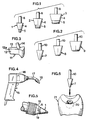
- Fig. 1 shows prefabricated, inventive inlays 1-3 which are made of a ceramic or glass-ceramic material whose properties are as similar to those of dental enamel as possible. This material should preferably be castable or industrially sintered, so that the inlays 1-3 may easily be produced in large series of high dimensional accuracy.
- the inlays 1-3 have a frustoconical part 4 having a circular cross-section and being adapted for insertion into a cavity in a tooth. At the narrow end of the frustoconical part 4, the inlays 1-3 have a recess in the form of a circumferential groove 5 serving to improve the mechanical retention of the inlay when this has been applied in the tooth cavity.
- the inlays 1-3 may, for the same purpose, be provided with raised portions which, however, must not project radially to such an extent that the inlays 1-3 cannot be inserted in the cavity at issue. Neither the depressions nor the raised portions are compulsory, since the retention needed can often be achieved all the same, especially if the inlays are etched.
- the thick end of the conical inlays 1-3 i.e. the inlay part not adapted for insertion, has an axially projecting pin 6 of preferably round cross-section.
- the narrow end of the conical part 4 preferably has a rounded shape.
- the cone angle of the frustoconical part 4 is approximately 28°.
- the invention is not restricted to this angle, but encompasses other cone angles as well.
- the inlays 1-3 can have different diameters at the narrow end but essentially the same height at the frustoconical part 4, as illustrated in Fig. 1.
- Fig. 2 is a side view of three different, frustoconical burrs 7-9.
- the burrs 7-9 have a diamond coating both on the circumferential surface of the frustoconical part and on the end surface of the narrow end.
- the burrs 7-9 have a shank 10 projecting axially from the thick end.
- the cone angle of the burrs 7-9 should be identical with that of the corresponding inlays 1-3 that are to be applied in cavities prepared by the burrs.
- Fig. 3 shows another embodiment of an inlay 11 according to the invention.
- This inlay 11 is substantially L-shaped and has, in accordance with the invention, two lateral surfaces 12, 13, which either are parallel or converge slightly downwards, on one branch of the L.
- This branch which is to be contained in the occlusal part of the cavity, has, in accordance with the invention, a conical end 12a, i.e. a partly conical portion.
- the end 12a may be partly cylindrical and be inclined obliquely inwards-downwards.
- the inlay 11 is intended to for making a "class II" filling, in which case the above branch is to be accommodated in an occlusal part of the cavity, while the other branch of the L is to be accommodated in a proximal part of the cavity.
- a pin 14 projects upwards from the future outer part of the occlusal surface of the inlay 11 at an acute angle to the branch with the lateral surfaces 12, 13.
- the pin 14 has the same shape as the pin 6 in Fig. 1, and the inlay 11 is made of the same material as the inlays 1-3 in Fig. 1.
- the inlay 11 may, when applied, be simply pressed against both the occlusal opening edges of the cavity and the adjoining tooth, thereby optimising positioning of the inlay 11 in the cavity, by the forces that act on the inlay 11 after restoration being directly transferred to the underlying original tooth material.
- the inlay can, when applied, be axially displaced, and consequently in mesiodistal direction, to optimise positioning in the cavity.
- an inlay holder 15 consists of a conventional curing lamp containing a light source 16, e.g. a halogen or laser light source, for generating light suitable for curing a light-curing material in order to fix e.g. the inlay 1 in a cavity prepared therefor.
- the curing lamp has a light guide 17 extending from the light source 16 out into a tip 18.
- a recess or hole 19 is, in accordance with the invention, provided in the free end of the light-guide tip 18 and has a cross-sectional shape corresponding to that of the pins 6, 14. This recess may be slightly conical, so that, after e.g.
- the pin 6 has been inserted therein, e.g. the inlay 1 is retained in a fixed position in the light-guide tip 18, there being good transmission from the light-guide tip 18 of the light generated by the light source 16 into the pin 6 and through the whole inlay 1.
- the cavity 20 is prepared by drilling its interior to a sufficient extent. Then, the opening of the cavity 20 is prepared by means of a burr of the type shown in Fig. 2. These steps may also be performed in the reverse order. Then, the internal surface of the cavity is insulated by a suitable insulating material, e.g. a glass ionomer. If a non-conical inlay, e.g. an inlay of the type shown in Fig.
- a gauge can be used for determining the size and the shape of the inlay.
- a conical inlay 1 with a size corresponding to the burr used.
- this inlay is pre-etched, and is cleaned, dried and silanised after being fixed in the inlay holder.
- the latter Prior to the application of the inlay 1 in the cavity 20, the latter may be etched with phosphoric acid and, after drying, be filled with a fixing material, e.g. a light-curing composite material.
- a dual composite which is not only slowly chemically curing but also rapidly light-curing.
- the inlay part adapted for insertion can be wetted with a resin. Then, the inlay 1 is pressed down into the cavity 20 until its circumferential surface makes firm contact with the opening of the cavity 20, whereupon the light source 16 of the inlay holder 15 is lit for rapid curing of the composite material, thereby fixing the inlay 1 in the cavity 20.
- the inlay holder 15 may then be removed by pulling the tip 18 off the pin 6. Alternatively, the pin 6 can be broken by means of the inlay holder 15. Finally, restoration is completed by grinding and polishing the exposed part of the inlay 1 to the desired shape and finish.
Landscapes
- Health & Medical Sciences (AREA)
- Oral & Maxillofacial Surgery (AREA)
- Dentistry (AREA)
- Epidemiology (AREA)
- Life Sciences & Earth Sciences (AREA)
- Animal Behavior & Ethology (AREA)
- General Health & Medical Sciences (AREA)
- Public Health (AREA)
- Veterinary Medicine (AREA)
- Dental Tools And Instruments Or Auxiliary Dental Instruments (AREA)
- Dental Preparations (AREA)
- Non-Portable Lighting Devices Or Systems Thereof (AREA)
Claims (13)
- Vorgefertigtes Inlay zur Wiederherstellung eines Zahnes durch Einfügen in eine präparierte Zahnkavität und Befestigen in selbiger, welche im wesentlichen die gleiche Form wie der einzusetzende Teil des Inlays aufweist,
dadurch gekennzeichnet, daß es einen Stift (6; 14) hat, der aus dem Teil des Inlays hervorsteht, welcher nicht eingesetzt wird, und der in einem Inlayhalter (15) aufgenommen werden kann, und dadurch, daß das gesamte Inlay (1; 11) aus einem Werkstoff besteht, der solches Licht durchläßt, welches sich zum Aushärten eines mittels Licht aushärtbaren Werkstoffs eignet, welcher zum Befestigen des Inlays in der Kavität verwendet wird. - Inlay gemäß Anspruch 1, dadurch gekennzeichnet, daß der Stift (6; 14) zum Fixieren in einer entsprechenden Aussparung (19) im Inlayhalter (15) einen runden Querschnitt aufweist.
- Inlay gemäß Anspruch 1 oder 2, dadurch gekennzeichnet, daß das Inlay (1) zumindest teilweise zylindrisch bzw. zumindest teilweise konisch ist.
- Inlay gemäß Anspruch 3, dadurch gekennzeichnet, daß das Inlay (1) zumindest in dem Teil, der zum Ausfüllen der Kavität vorgesehen ist, vollkommen konisch ist.
- Inlay gemäß einem der Ansprüche 1-4, dadurch gekennzeichnet, daß es aus einem keramischen oder einem glaskeramischen Werkstoff hergestellt ist.
- Inlay gemäß einem der Ansprüche 1-5, dadurch gekennzeichnet, daß der Teil des Inlays, der eingesetzt wird (z.B. 4), erhöhte Abschnitte und/oder Vertiefungen (5) aufweist, mit denen der mechanische Halt verbessert wird.
- Inlay gemäß einem der Ansprüche 1-6, dadurch gekennzeichnet, daß es vorgeätzt ist.
- Inlayhalter zum Einbringen eines vorgefertigten Inlays (1; 11) in eine präparierte Zahnkavität, welche im wesentlichen die gleiche Form wie der Teil des Inlays hat, der eingesetzt wird, gekennzeichnet durch eine Lichtquelle (16) zum Erzeugen von Licht, das sich zum Aushärten eines Lichtaushärtwerkstoffs zwecks Befestigung des Inlays (1) in der Kavität eignet, und eine Lichtführung (17), welche das Licht aus der Lichtquelle empfängt und eine Spitze (18) mit einer Aussparung (19) zur Aufnahme des Stifts (6; 14) hat, der aus dem Teil des Inlays hervorsteht, der nicht eingesetzt wird, so daß das von der Lichtquelle (16) erzeugte Licht durch die Lichtführung (17) und das Inlay (1; 11) zu dem Lichtaushärtwerkstoff gelangen kann.
- Inlayhalter gemäß Anspruch 8, dadurch gekennzeichnet, daß die Aussparung (19) einen runden Querschnitt hat.
- Inlayhalter gemäß Anspruch 8 oder 9, dadurch gekennzeichnet, daß die Lichtquelle (16) blaues Licht mit einer Wellenlänge zwischen 400 und 500 nm erzeugt.
- Zahnwiederherstellungsset, gekennzeichnet durch eine Vielzahl vorgefertigter kegelstumpfförmiger Inlays (1), die vorzugsweise den gleichen Kegelwinkel sowie verschiedene Durchmesser am schmalen Ende haben, und durch eine Vielzahl kegelstumpfförmiger Bohrer (7-9) mit dem gleichen Kegelwinkel wie die Inlays (1) und den entsprechenden unterschiedlichen Durchmessern am schmalen Ende, wobei jedes Inlay (1) einen Stift (6) hat, der vom breiten Ende hervorsteht und in einem Inlayhalter aufgenommen werden kann, und die Inlays (1) solches Licht durchlassen, welches sich zum Aushärten eines Lichtaushärtwerkstoffs eignet, der zum Befestigen eines Inlays in einer Zahnkavität verwendet wird.
- Set gemäß Anspruch 11, dadurch gekennzeichnet, daß die Inlays (1) derart in einem Behälter fixiert sind, daß sie allein mit Hilfe eines Inlayhalters (15) aus dem Behälter entnommen werden können.
- Set gemäß Anspruch 11 oder 12, dadurch gekennzeichnet, daß die Bohrer (7-9) Diamantbohrer sind, die auch auf der Stirnseite des schmalen Endes diamantbeschichtet sind.
Applications Claiming Priority (5)
| Application Number | Priority Date | Filing Date | Title |
|---|---|---|---|
| SE9200020 | 1992-01-07 | ||
| SE9200020A SE9200020D0 (sv) | 1992-01-07 | 1992-01-07 | Prefabricerade keramiska inlaegg foer anvaendning inom tandvaarden |
| SE9202428A SE470250B (sv) | 1992-01-07 | 1992-08-25 | Inlägg, inläggsbärare samt tandrestaureringsset |
| SE9202428 | 1992-08-25 | ||
| PCT/SE1993/000002 WO1993013726A1 (en) | 1992-01-07 | 1993-01-04 | Inlay, inlay holder, method for tooth restoration, and tooth restoration set for carrying out the method |
Publications (2)
| Publication Number | Publication Date |
|---|---|
| EP0620721A1 EP0620721A1 (de) | 1994-10-26 |
| EP0620721B1 true EP0620721B1 (de) | 1998-05-20 |
Family
ID=26661290
Family Applications (1)
| Application Number | Title | Priority Date | Filing Date |
|---|---|---|---|
| EP93901429A Expired - Lifetime EP0620721B1 (de) | 1992-01-07 | 1993-01-04 | Inlay, inlayhalter sowie zahnwiederherstellungsset |
Country Status (7)
| Country | Link |
|---|---|
| US (1) | US5567156A (de) |
| EP (1) | EP0620721B1 (de) |
| AU (1) | AU3271593A (de) |
| DE (1) | DE69318697T2 (de) |
| ES (1) | ES2115751T3 (de) |
| SE (1) | SE470250B (de) |
| WO (1) | WO1993013726A1 (de) |
Families Citing this family (15)
| Publication number | Priority date | Publication date | Assignee | Title |
|---|---|---|---|---|
| DE4339399A1 (de) * | 1993-11-18 | 1995-05-24 | Thera Ges Fuer Patente | Durch Polymerisation einer ethylenisch polymerisierbaren Masse in Formen hergestellte Formkörper (Inserts) |
| DE4439410A1 (de) * | 1994-11-04 | 1996-05-09 | Kaltenbach & Voigt | System zur Beseitigung eines Defektes an einem Zahn |
| US5695340A (en) * | 1995-06-26 | 1997-12-09 | Lee Pharmaceuticals | Dental restoration system and method |
| SE9503299L (sv) * | 1995-09-25 | 1996-09-23 | Nordiska Dental Ab | Tandborr |
| DE19602500C2 (de) * | 1996-01-24 | 2003-02-13 | Ivoclar Vivadent Ag | Formkörper |
| DK92896A (da) * | 1996-08-30 | 1998-03-01 | Gregers Lystager | Lysleder til hærdning af tandfyldningskomposit |
| DE19736238A1 (de) | 1997-08-20 | 1999-02-25 | Kaltenbach & Voigt | Dentalmedizinisches Werkzeug zur Präparation eines Zahnes für eine Zahn-Krone |
| RU2171653C1 (ru) * | 1999-11-30 | 2001-08-10 | Савинов Игорь Владимирович | Способ изготовления пломбировочных вкладок |
| EP1333768B1 (de) * | 2000-10-26 | 2006-08-16 | Globodent EHF. | VorrichtUNG ZUR ZAHNBEHANDLUNG |
| IS6777A (is) * | 2003-04-10 | 2004-03-15 | Globodent Ehf. | Mótaðar tannfyllingar |
| RU2252728C1 (ru) * | 2003-11-24 | 2005-05-27 | Садыков Мукатдес Ибрагимович | Способ изготовления цельнолитой культевой штифтовой вкладки |
| DE602005012544D1 (de) * | 2004-12-14 | 2009-03-12 | Aproxi Aps | Vorgefertigtes zahnärztliches insert |
| ES2526547T3 (es) * | 2005-08-10 | 2015-01-13 | Dentsply International Inc. | Procedimientos para preparar coronas dentales en la consulta |
| WO2016116951A1 (en) | 2015-01-22 | 2016-07-28 | Egill Jonsson | Methods and devices for repairing tooth cavities |
| US20240016575A1 (en) * | 2022-07-12 | 2024-01-18 | Perfect Fit Crowns Llc | Method and apparatus for dental crown restorations using prefabricated sleeve-crown pairs |
Family Cites Families (11)
| Publication number | Priority date | Publication date | Assignee | Title |
|---|---|---|---|---|
| CH608957A5 (de) * | 1977-02-25 | 1979-02-15 | Leuthard Paul E | |
| SE435447B (sv) * | 1983-02-21 | 1984-10-01 | Dan Ericson | Sett och anordning for framstellning av en tandfyllning av ljusherdande material |
| US4666406A (en) * | 1984-01-13 | 1987-05-19 | Kanca Iii John | Photocuring device and method |
| US4726770A (en) * | 1985-01-12 | 1988-02-23 | Kurer Hans G | Tooth restoration and means for use therein |
| FR2577796B1 (fr) * | 1985-02-28 | 1987-06-19 | Touati Bernard | Fixation de pieces rigides telle qu'une prothese dentaire |
| DE3743433C1 (de) * | 1987-12-21 | 1989-05-24 | Dieter Dr Schuhmacher | Keramik-Formkoerper |
| US4971558A (en) * | 1988-03-30 | 1990-11-20 | Board Of Regents Of The University Of Oklahoma | Porcelain inlay formed directly in a cavity and method for making same |
| US5030093A (en) * | 1988-06-10 | 1991-07-09 | Aaron Teitelbaum | Method and apparatus for dental restorative material |
| US5017140A (en) * | 1989-05-15 | 1991-05-21 | Jay Ascher | Removable and disposable extension for a light guide of a dental curing light and its method of use |
| NO172373C (no) * | 1990-11-26 | 1993-07-14 | Baard Bjerknes | Fremgangsmaate for tilpasning og implantering av dental porselensbrikke |
| US5272184A (en) * | 1992-09-28 | 1993-12-21 | Itzhak Shoher | Metal composite and method for filling a dental cavity in the preparation of a dental restoration |
-
1992
- 1992-08-25 SE SE9202428A patent/SE470250B/sv not_active IP Right Cessation
-
1993
- 1993-01-04 EP EP93901429A patent/EP0620721B1/de not_active Expired - Lifetime
- 1993-01-04 AU AU32715/93A patent/AU3271593A/en not_active Abandoned
- 1993-01-04 DE DE69318697T patent/DE69318697T2/de not_active Expired - Fee Related
- 1993-01-04 WO PCT/SE1993/000002 patent/WO1993013726A1/en not_active Ceased
- 1993-01-04 US US08/256,277 patent/US5567156A/en not_active Expired - Fee Related
- 1993-01-04 ES ES93901429T patent/ES2115751T3/es not_active Expired - Lifetime
Also Published As
| Publication number | Publication date |
|---|---|
| AU3271593A (en) | 1993-08-03 |
| DE69318697T2 (de) | 1998-12-03 |
| ES2115751T3 (es) | 1998-07-01 |
| EP0620721A1 (de) | 1994-10-26 |
| US5567156A (en) | 1996-10-22 |
| SE9202428D0 (sv) | 1992-08-25 |
| WO1993013726A1 (en) | 1993-07-22 |
| DE69318697D1 (de) | 1998-06-25 |
| SE470250B (sv) | 1993-12-20 |
| SE9202428L (sv) | 1993-07-08 |
Similar Documents
| Publication | Publication Date | Title |
|---|---|---|
| EP0620721B1 (de) | Inlay, inlayhalter sowie zahnwiederherstellungsset | |
| US11116613B2 (en) | Molds for custom dental implant abutments and impression posts | |
| US4575340A (en) | Precision dental restorative system | |
| US5989029A (en) | Customized dental abutments and methods of preparing or selecting the same | |
| US6641340B1 (en) | Apparatus and method for machining a prosthetic tooth restoration | |
| US5192207A (en) | Composite resin crown, replacement tooth and method | |
| KR100676096B1 (ko) | 임플란트 지지된 의치 및 이의 제조방법 | |
| WO2001034056A1 (en) | One-part dental implant | |
| JPH11502136A (ja) | 歯科用インプラントの円錐状副部材への結合構造 | |
| US4971558A (en) | Porcelain inlay formed directly in a cavity and method for making same | |
| CA2534455C (en) | Dental implant system | |
| US20060147881A1 (en) | Multi-functional dental post | |
| US5697787A (en) | Dental inserts | |
| US4934936A (en) | Dental anchor for retention of dental restoration | |
| US5507643A (en) | Kit, tool and method of use for securing a dental restoration on a prepared tooth stub | |
| JP2025078035A (ja) | 人工歯冠及びその製造方法 | |
| JPH0323856A (ja) | 人工歯根 | |
| CN214231577U (zh) | 适用于牙种植体及天然牙的预制嵌体 | |
| US6953339B1 (en) | Tip for dental curing light | |
| RU19681U1 (ru) | Пломба-вкладка | |
| US20240423766A1 (en) | Dental Analog | |
| JP2008506485A (ja) | 歯冠上部構造システム用上部構造体 | |
| KR200338093Y1 (ko) | 세라믹층을 가진 티타늄 어버트먼트 | |
| KR20230168327A (ko) | 픽스쳐로부터 어버트먼트 스크류를 제거할 수 있는 어버트먼트 스크류 제거 장치 | |
| CN115919491A (zh) | 一种非同轴种植系统及其设计方法 |
Legal Events
| Date | Code | Title | Description |
|---|---|---|---|
| PUAI | Public reference made under article 153(3) epc to a published international application that has entered the european phase |
Free format text: ORIGINAL CODE: 0009012 |
|
| 17P | Request for examination filed |
Effective date: 19940628 |
|
| AK | Designated contracting states |
Kind code of ref document: A1 Designated state(s): DE ES FR GB IT |
|
| 17Q | First examination report despatched |
Effective date: 19961211 |
|
| GRAG | Despatch of communication of intention to grant |
Free format text: ORIGINAL CODE: EPIDOS AGRA |
|
| GRAG | Despatch of communication of intention to grant |
Free format text: ORIGINAL CODE: EPIDOS AGRA |
|
| GRAH | Despatch of communication of intention to grant a patent |
Free format text: ORIGINAL CODE: EPIDOS IGRA |
|
| GRAH | Despatch of communication of intention to grant a patent |
Free format text: ORIGINAL CODE: EPIDOS IGRA |
|
| GRAA | (expected) grant |
Free format text: ORIGINAL CODE: 0009210 |
|
| AK | Designated contracting states |
Kind code of ref document: B1 Designated state(s): DE ES FR GB IT |
|
| ITF | It: translation for a ep patent filed | ||
| REF | Corresponds to: |
Ref document number: 69318697 Country of ref document: DE Date of ref document: 19980625 |
|
| REG | Reference to a national code |
Ref country code: ES Ref legal event code: FG2A Ref document number: 2115751 Country of ref document: ES Kind code of ref document: T3 |
|
| ET | Fr: translation filed | ||
| PLBE | No opposition filed within time limit |
Free format text: ORIGINAL CODE: 0009261 |
|
| STAA | Information on the status of an ep patent application or granted ep patent |
Free format text: STATUS: NO OPPOSITION FILED WITHIN TIME LIMIT |
|
| 26N | No opposition filed | ||
| REG | Reference to a national code |
Ref country code: GB Ref legal event code: IF02 |
|
| PG25 | Lapsed in a contracting state [announced via postgrant information from national office to epo] |
Ref country code: IT Free format text: LAPSE BECAUSE OF NON-PAYMENT OF DUE FEES Effective date: 20050104 |
|
| PGFP | Annual fee paid to national office [announced via postgrant information from national office to epo] |
Ref country code: FR Payment date: 20050125 Year of fee payment: 13 Ref country code: ES Payment date: 20050125 Year of fee payment: 13 |
|
| PGFP | Annual fee paid to national office [announced via postgrant information from national office to epo] |
Ref country code: GB Payment date: 20051213 Year of fee payment: 14 |
|
| PG25 | Lapsed in a contracting state [announced via postgrant information from national office to epo] |
Ref country code: ES Free format text: LAPSE BECAUSE OF NON-PAYMENT OF DUE FEES Effective date: 20060105 |
|
| PGFP | Annual fee paid to national office [announced via postgrant information from national office to epo] |
Ref country code: DE Payment date: 20060119 Year of fee payment: 14 |
|
| PG25 | Lapsed in a contracting state [announced via postgrant information from national office to epo] |
Ref country code: FR Free format text: LAPSE BECAUSE OF NON-PAYMENT OF DUE FEES Effective date: 20060131 |
|
| REG | Reference to a national code |
Ref country code: FR Ref legal event code: ST Effective date: 20060929 |
|
| REG | Reference to a national code |
Ref country code: ES Ref legal event code: FD2A Effective date: 20060105 |
|
| PG25 | Lapsed in a contracting state [announced via postgrant information from national office to epo] |
Ref country code: DE Free format text: LAPSE BECAUSE OF NON-PAYMENT OF DUE FEES Effective date: 20070801 |
|
| GBPC | Gb: european patent ceased through non-payment of renewal fee |
Effective date: 20070104 |
|
| PG25 | Lapsed in a contracting state [announced via postgrant information from national office to epo] |
Ref country code: GB Free format text: LAPSE BECAUSE OF NON-PAYMENT OF DUE FEES Effective date: 20070104 |
|
| PGFP | Annual fee paid to national office [announced via postgrant information from national office to epo] |
Ref country code: IT Payment date: 20060131 Year of fee payment: 14 |
|
| PGRI | Patent reinstated in contracting state [announced from national office to epo] |
Ref country code: IT Effective date: 20080301 |
|
| PGRI | Patent reinstated in contracting state [announced from national office to epo] |
Ref country code: IT Effective date: 20080301 |