EP0620792B1 - Schubumkehr mit einer integrierten düse mit veränderlichem strahlquerschnitt - Google Patents
Schubumkehr mit einer integrierten düse mit veränderlichem strahlquerschnitt Download PDFInfo
- Publication number
- EP0620792B1 EP0620792B1 EP93903557A EP93903557A EP0620792B1 EP 0620792 B1 EP0620792 B1 EP 0620792B1 EP 93903557 A EP93903557 A EP 93903557A EP 93903557 A EP93903557 A EP 93903557A EP 0620792 B1 EP0620792 B1 EP 0620792B1
- Authority
- EP
- European Patent Office
- Prior art keywords
- doors
- thrust reverser
- jet engines
- exhaust
- shells
- Prior art date
- Legal status (The legal status is an assumption and is not a legal conclusion. Google has not performed a legal analysis and makes no representation as to the accuracy of the status listed.)
- Expired - Lifetime
Links
- 238000011144 upstream manufacturing Methods 0.000 description 7
- 239000012530 fluid Substances 0.000 description 4
- 230000008901 benefit Effects 0.000 description 3
- 230000015556 catabolic process Effects 0.000 description 3
- 238000006731 degradation reaction Methods 0.000 description 3
- 239000003570 air Substances 0.000 description 2
- 238000009434 installation Methods 0.000 description 2
- 238000007789 sealing Methods 0.000 description 2
- 239000012080 ambient air Substances 0.000 description 1
- 238000010276 construction Methods 0.000 description 1
- 238000006073 displacement reaction Methods 0.000 description 1
- 230000000694 effects Effects 0.000 description 1
Images




Classifications
-
- F—MECHANICAL ENGINEERING; LIGHTING; HEATING; WEAPONS; BLASTING
- F02—COMBUSTION ENGINES; HOT-GAS OR COMBUSTION-PRODUCT ENGINE PLANTS
- F02K—JET-PROPULSION PLANTS
- F02K1/00—Plants characterised by the form or arrangement of the jet pipe or nozzle; Jet pipes or nozzles peculiar thereto
- F02K1/54—Nozzles having means for reversing jet thrust
- F02K1/56—Reversing jet main flow
- F02K1/60—Reversing jet main flow by blocking the rearward discharge by means of pivoted eyelids or clamshells, e.g. target-type reversers
Definitions
- This invention relates to a thrust reverser for jet engines, especially the type used on aircraft. More particularly, the invention relates to a thrust reverser which integrates a variable exhaust area nozzle.
- thrust reversers are utilized on the jet engines in order to provide a braking thrust for the aircraft.
- thrust reversers are formed by thrust reverser "doors" which are capable of pivoting between two positions about an axis which is transverse and substantially diametrical with respect to the jet of the engine.
- the first position finds the doors in a stowed position, out of the direct path of the exhaust blast of the engine.
- the doors form the exhaust nozzle of the gas turbine engine so that the thrust of the engine is directly rearward, thereby producing the forward thrust of the aircraft.
- the doors are pivoted about the pivot axis to a transverse, blast deflecting or deployed position, to intercept and redirect the jet blast and produce the braking thrust for the aircraft when needed.
- the trailing edge of the reverser doors must be fully scarfed to enable the deployment of the doors and the butting of the trailing edges of the two doors against one another in the deployed position. This scarfing produces what is known as a "fishmouth" shape at the exhaust outlet because of its appearance when viewed from the side.
- variable area exhaust nozzles for thrust reversers are shown in U.S. Patent 4,966,327 and French Patent 2,614,939.
- a variable area exhaust provides certain benefits for the jet engines, in enabling them to adapt to different conditions of the flight. For example, different characteristics of the engines are desirable for take off, climb and cruise modes of operation, and varying the exhaust area enables the engine to better achieve the optimum characteristics.
- the thrust reverser doors do not (and cannot) in any of the controllable positions of the reverser doors define the throat of the exhaust nozzle to be at the trailing edge of the nozzle/reverser doors.
- the inner flow line of the thrust reverser doors is convergent to the throat, with a cylindrical extension aft of the throat. This means that at any position of the thrust reverser nozzle, the throat of the nozzle always remains significantly upstream of the reverser nozzle trailing edge. This is an inherent characteristic in the design of the prior art as it is described in French patent 2,382,594.
- a primary object of the present invention is to provide a thrust reverser which overcomes the aforementioned disadvantages of prior art thrust reversers.
- a further object of the invention is to provide an improved thrust reverser which integrates a variable area exhaust nozzle.
- Yet another object of the invention is to provide a thrust reverse in which variation in the area of the exhaust throat takes place at the trailing edge of the planar nozzle.
- Still a further object of the invention is to provide a thrust reverser construction wherein the reverser doors are the operating means for the exhaust nozzle in order to optimize the engine operating characteristics for different phases of the flight.
- the present invention provides a thrust reverser formed by a pair of doors, each door being pivotally mounted on a substantially diametrically arranged pivot axis.
- the inner skins of the doors are scarfed to enable their deployment by pivoting about the pivot axis.
- a pair of half shells surround the thrust reverser doors, and the exhaust nozzle is formed by the shells rather than the thrust reverser doors.
- the throat is preferably coincident with the trailing edge of the shells in either of the positions of the shells.
- the shells are mounted so that they are actuated by an actuator between the various positions of the exhaust nozzle, and controlled according to the flight condition of the aircraft.
- a further actuator is provided for the thrust reverser function, for pivoting the doors to the reversing position, and preferably a latching mechanism is also provided for the reverser doors.
- FIGURE 1 illustrates schematically the prior art thrust reversers, for example the type disclosed in French patents 2,382,594 and 2,614,939, or in U.S. patent 4,966,327.
- the small exit area (or cruise) configuration is represented by the solid line position, while the take-off or large exit area configuration is represented in the dashed line position.
- the throat 10 of the nozzle is upstream of the trailing edge 12 of the thrust reverser door at a distance 'd' which is equal to the length of the cylindrical extension 14.
- the profile of the inner flow contour defined by portions 14 and 16 is necessarily either convergent-cylindrical or convergent-divergent, as the extension 14 may be designed to be either cylindrical or divergent. But, the nozzle cannot be purely convergent.
- FIGURE 2 shows a similar schematic representation for the present invention.
- the fishmouth portion of the exhaust nozzle is effectively eliminated for all positions of the exhaust nozzle, and therefor does not cause the same degradation of engine performance, since no efflux spillage can occur. This is a consequence of the planar exit of the nozzle.
- the throat 20 of the exhaust nozzle is defined by the trailing edge of a pair of half-shells 22 which surround the thrust reverser doors 24, and not by the thrust reverser doors 24 themselves.
- the new throat 20' is still defined by the trailing edge of the half-shells 22.
- the inner flow line of the exhaust nozzle can be purely convergent, which is a test configuration for optimum cruise performance.
- the inner profile can be either purely convergent, or can become divergent.
- the exhaust system according to the invention is seen to comprise two identical thrust reverser doors 30 having outer skins 32 which insure the continuity of the outer flow with the fixed upstream structure or jet pipe 34 of the nacelle.
- the inner skins 36 of the doors 30 are fully scarfed in order to enable pivotal deploying of the reverser doors.
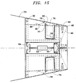
- each thrust reverser door 30 can either be fixed as shown in FIGURE 3, or can be movable as shown in FIGURE 15. In either case, the inner skin 36 is essentially of a hemi-truncated shape, ensuring the continuity of the jet flow with that of the jet pipe 34.
- a flange 38 extends from each thrust reverser door and serves to mount the doors 30 for pivotal movement about the axis 40. Since the inner skins 36 are fully scarfed, the thrust reverser doors may pivot to their deployed position by pivoting about the axes 40, so that the trailing edges 42 of each door 30 come into abutting contact, either directly or through abutment fittings (not shown).
- Two half-shells 44 surround the rear portion of the doors 30 and form the exhaust nozzle by ensuring the inner flow continuity of the inner skins 36 of the thrust reverser doors 30.
- the half-shells 44 have a planar exit with the throat 46 being defined by their trailing edge.
- the half-shells are also pivotally mounted to two mounting arms 56. As will be seen below, these arms 56 permit varying the throat area for any desired positions of the thrust reverser doors, when the doors are in the stowed position, and also permit pivoting of the half-shells when the doors are pivoted to their deployed position.
- the system include a first actuator system 50 (FIGURE 15) for varying the area of the exhaust nozzle, a second actuator system 52 for actuating the thrust reverser doors, and a latching mechanism 54 for securing the doors 30.
- a sealing arrangement is provided to insure a lea]c free installation.
- the nozzle In the position shown for the thrust reverser doors in FIGURES 3 and 15, the nozzle is in the small exit area configuration which corresponds to the cruise position, and it is important to note that in this configuration, there are no flow discontinuities, either for the inner jet flow or for the outer ambient air flow. Since most of the flight duration is in the cruise mode, it is essential that this condition be observed in order to achieve optimum performance in the cruise mode.
- each of the doors 30 is hinged about an axis 40 arranged substantially diametrically of the jet pipe 34.
- the axis 40 for each door can be moved to different positions when the arms 48 are moved to different angular positions by the actuating system 50.
- the half-shells 44 are pivotally mounted to the arms 56 at pivot axes 58, and the arms 48 and 56 are pivotally connected as well at the pivot axes 40 of the thrust reverser doors 30.
- the arms 48 are pivotally mounted at 49 to the jet pipe.
- the linkage connecting these half-shells to the doors essentially comprises a link 59 hinged to the thrust reverser door at one end and hinged to the half-shell at the other end.
- FIGURE 13 shows a schematic representation of the three positions of the exhaust nozzle, i.e. cruise, unlatch, and take-off.
- movement may be to either of the extreme positions (i.e. cruise or take-off) or may be to infinitely variable or predetermined positions between the two extremes.
- the actuator for example, should be a linear type actuator so as to provide linear motion of the rod 62.
- the actuator may be a hydraulic or pneumatic piston and cylinder, or may be a solenoid, or may be a screw or rack and pinion type actuator.
- the present invention is not restricted to the detailed configuration of the particular type of actuator used, however, the principles of the invention may nonetheless be fully understood without further description of the details of the actuator.
- the pivot point 40 for the reverser doors moves in an arcuate path as the actuator 50 is actuated, and this in turn causes pivoting of the arm 48 about the pivot point 49 and movement of the pivot point 40 in an arcuate path.
- the latch receptacle 66 moves with respect to the latch arm 54.
- the adjustment of the exhaust nozzle size is accommodated by this allowed movement of the latch receptacle, while the door, and the latch arm, remain in the stowed position.
- the latch arm 54 has a ramp portion 68 which serves to lower the upper portion 70 of the leading edge 72 of the thrust reverser doors 40, when the axis 40 is moved to the take-off position.
- each upper corner 70 to penetrate inside the fixed structure 34. It also allows the small rotation of each reverser door around its respective latch receptacle during the opening of the exhaust nozzle defined by the half-shells 44 from cruise to take-off positions. Further, as best seen in FIGURE 6, there is no discontinuity between the outer envelope of the structure 34 and the outer skin 32 of the thrust reverser doors 30.
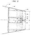
- the driving mechanism or actuator 50 drives the arms 48 through links 60 in order to unlatch the rotation axis 40 of the thrust reverser doors 30.
- the thrust reverser doors are stowed (FIGURE 13).
- the doors 30 close the exhaust area of the variable nozzle, defined by the half-shells 44, in the manner described above. Again, these half-shells which form the nozzle, are supported at 58 by the arms 48 which rotate around the thrust reverser door rotation axis 40.
- the doors maintain the fluid tightness between the fixed structure 34 and the inner skin 36 by means of seal 75.
- the actuator rod connected to the links 60 is guided by any suitable track or guide (not shown).
- the exhaust area of the variable nozzle is the same as that of FIGURE 3, i.e. in the cruise mode with the minimum dimension S1. However, in FIGURE 5, the variable nozzle is unlatched, ready to be moved to the fully opened or take-off position.
- variable exhaust area nozzle is shown in the fully opened or take-off position (S2).
- the half-shells 44 have been driven about their upstream pivot axis 40 by the reverser doors 30 and links 59 as well as by arms 56.
- the thrust reverser doors 30 which have pivoted about the axis 40 as well as their latch arm 54, still maintain the airtight relationship with the fixed structure 34 and the inner skin 36 of the reverser doors by means of the seal 75. It is important to note that this configuration also ensures internal flow continuity of the profile.
- the shells 44 are comprised of outer skins 90, which ensure continuity with the outer skins 32 of the doors 30, and inner skins 92 which envelope the inner skins 36 of the doors 30 and also form the exhaust nozzle of the jet engine.
- outer skins 90 which ensure continuity with the outer skins 32 of the doors 30, and inner skins 92 which envelope the inner skins 36 of the doors 30 and also form the exhaust nozzle of the jet engine.
- inner skins 92 which envelope the inner skins 36 of the doors 30 and also form the exhaust nozzle of the jet engine.
- Air tightness is ensured by a longitudinal seal installed between the inner skins 92 on the two half-shells.
- FIGURES 9 and 10 show another arrangement of the cross-section of the shells 44.
- this arrangement there is a fixed center beam 94 which ensures the continuity of the inner and outer profiles of the nozzle and also fluid tightness.
- This center beam is attached to the fixed structure 34, thus forming an extended arm.
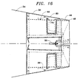
- the thrust reverser doors 30 are shown in their deployed positions.
- the doors 30 have been moved into this position by the actuation system 52 with the actuation system 50 of the variable nozzle in the cruise configuration.
- the thrust reverser doors 30 drive through their respective linkage 59 the half-shells 44, which in turn pivot about their axis 58.
- the shells 44 which formed the variable exhaust nozzle when the doors were in the stowed configuration are surrounding their respective door 30, allowing the inner skin 36 to penetrate inside the shells and thus abut on their trailing edge (or abutment fittings) along the centerline of the thrust reverser exhaust nozzle.
- the inner skins 36 are trimmed, although this has no effect on the continuity of the inner profile of the variable nozzle, since this occurs outboard of the inner skins 36, at 90° from the pivot axis 40 of the doors, i.e. where the fishmouth extension of the inner skin is at a maximum.
- FIGURE 11 air tightness between the fixed structure 34 and the movable skin 74 is also ensured.
- FIGURE 12 when the variable exhaust nozzle has been opened to its take-off position.
- the longitudinal seal is shown on the outboard face of member 34, in an alternative embodiment the seal could be applied on the inboard face of the member 88.
- the airtightness of the upstream radial portions of the seal is ensured by the V-shaped lever 78, as the extremity 82 has rolled on the fixed ramp 86 attached to the fixed structure 34.
- FIGURE 14 shows the thrust reverser deployed with the control system 50 of the reverser door axis 40 in the cruise configuration
- the system can be designed to deploy when the control system 50 is in the fully opened position (corresponding to the take-off position.)
Landscapes
- Engineering & Computer Science (AREA)
- Chemical & Material Sciences (AREA)
- Combustion & Propulsion (AREA)
- Mechanical Engineering (AREA)
- General Engineering & Computer Science (AREA)
- Supercharger (AREA)
- Control Of Turbines (AREA)
Claims (17)
- Schubumkehrer für Düsentriebwerke, umfassend ein Paar symmetrischer Schubumkehrer-Öffnungsklappenelemente (24, 30), wobei jedes der genannten Öffnungsklappenelemente schwenkbar auf einer Achse (40) montiert ist, die im wesentlichen diametrisch in bezug auf die Schubdüse eines Triebwerkes positioniert ist, um zwischen einer Stauposition, in der sich die genannten Öffnungsklappen außerhalb des direkten Abgasweges aus dem Triebwerk befinden, und einer Betriebsposition geschwenkt werden können, in der sich die genannten Öffnungsklappen im Pfad des Triebwerksabgases befinden, um das Abgas abzulenken und einen Bremsschub zu erzeugen, wobei die genannten Öffnungsklappen eine ausgeschärfte Hinterkante (42) aufweisen, gekennzeichnet durch ein Paar Halbschalen (22, 44), die wenigstens die Hinterkanten der genannten Öffnungsklappen umgeben und einen planaren Abgasauslaß für das Triebwerk bilden und schwenkbar an einem Montagearm (56) montiert sind, wobei der genannte Montagearm schwenkbar auf den genannten Achsen (40) montiert ist, ein erstes Stellglied (50) zum Bewegen der genannten Öffnungsklappenmontageachsen und somit zum Bewegen der genannten Umkehreröffnungsklappen und der genannten Halbschalen zum Verändern des Bereiches des genannten planaren Abgasauslasses zwischen den Mindest- und Höchst-Abgasbereichspositionen, und ein zweites Stellglied (52) zum Schwenken der genannten Öffnungsklappen zwischen der genannten Stau- und der genannten Betriebsposition.
- Schubumkehrer für Düsentriebwerke nach Anspruch 1, bei dem die genannten Halbschalen (44) schwenkbar an ersten Verbindungsarmen (56) unterhalb der genannten Achsen (40) und die genannten Schwenkarme schwenkbar an den genannten Achsen (40) montiert sind.
- Schubumkehrer für Düsentriebwerke nach Anspruch 2, umfassend Übertot-Gestängemittel (48, 60) zwischen dem genannten ersten Stellglied (50) und den genannten Achsen (40).
- Schubumkehrer für Düsentriebwerke nach Anspruch 3, umfassend ein Verbindungselement (59), das die genannten Schubumkehrer-Öffnungsklappen und die genannten Halbschalen an Punkten verbindet, die etwa 90° von den genannten Achsen beabstandet sind.
- Schubumkehrer für Düsentriebwerke nach Anspruch 4, bei dem das genannte erste und das genannte zweite Stellglied (50, 52) lineare Stellglieder umfaßt.
- Schubumkehrer für Düsentriebwerke nach Anspruch 3, bei dem das genannte Übertot-Gestängemittel an jedem Schwenkpunkt einen zweiten Verbindungsarm (48) umfaßt, der schwenkbar an einem Ende an den genannten Achsen (40) montiert und am anderen Ende mit einem dritten Verbindungsarm (60) verbunden ist, wobei der genannte zweite Verbindungsarm schwenkbar an einer festen Struktur zwischen den genannten Enden montiert ist, wobei die genannten dritten Verbindungsarme mit dem genannten zweiten Stellglied verbunden sind.
- Schubumkehrer für Düsentriebwerke nach Anspruch 6, bei dem das genannte erste Stellglied die Schwenkpunkte (40) der genannten Umkehreröffnungsklappen in eine bogenförmige Bahn bewegt.
- Schubumkehrer für Düsentriebwerke nach Anspruch 1, umfassend ein Dichtungsmittel (75, 77) zum Verhindern eines Abgaslecks im Bereich zwischen den genannten Öffnungsklappen und der Triebwerksstruktur.
- Schubumkehrer für Düsentriebwerke nach Anspruch 8, bei dem das genannte Dichtungsmittel eine bewegliche Innenhaut (74) aufweist, um die Dichtung aufrecht zu erhalten, wenn der Bereich des genannten Abgasauslasses verändert wird.
- Schubumkehrer für Düsentriebwerke nach Anspruch 1, umfassend eine Rastklinke (54) zum Befestigen des hinteren Abschnitts der genannten Öffnungsklappen in der Stauposition.
- Schubumkehrer für Düsentriebwerke nach Anspruch 10, bei dem die genannte Raste ein Mittel (66) zur Aufnahme der Bewegung der genannten Schubumkehrer-Öffnungsklappen umfaßt, wenn der Bereich des genannten Abgasauslasses verändert wird, ohne die Raste zu lösen.
- Schubumkehrer für Düsentriebwerke nach Anspruch 1, bei dem die genannten Schubumkehrer-Öffnungsklappen keine Durchflußunterbrechungen verursachen, wenn sich die genannten Öffnungsklappen in der genannten Stauposition befinden.
- Schubumkehrer für Düsentriebwerke nach Anspruch 1, bei dem die Schubdüsen in der genannten Stauposition eine konvergierende Düse ist.
- Schubumkehrer für Düsentriebwerke nach Anspruch 1, bei dem sich der Kehlbereich der Schubdüse an der Hinterkante der Düse befindet.
- Schubumkehrer für Düsentriebwerke nach Anspruch 1, bei dem die Bewegung der genannten Schubumkehrer-Öffnungsklappen eine entsprechende Bewegung der genannten Halbschalen bewirkt.
- Schubumkehrer für Düsentriebwerke nach Anspruch 15, umfassend ein Verbindungselement (59) zum Verbinden der genannten Öffnungsklappen und der genannten Halbschalen zum Bewegen der genannten Halbschalen von den genannten Öffnungsklappen weg in der Betriebsposition der genannten Öffnungsklappen.
- Schubumkehrer für Düsentriebwerke, umfassend ein Paar symmetrischer Schubumkehrer-Öffnungsklappenelemente (24, 30), wobei jedes der genannten Öffnungsklappenelemente schwenkbar auf einer Achse (40) montiert werden kann, die in bezug auf die Schubdüse eines Triebwerkes im wesentlichen diametrisch positioniert ist, um zwischen einer Stauposition, die keine inneren oder äußeren Durchflußunterbrechungen verursacht, und einer Betriebsposition zu schwenken, wobei die genannten Öffnungsklappen ausgeschärfte Hinterkanten (42) aufweisen, um die genannte Schwenkbewegung zu ermöglichen, gekennzeichnet durch ein Paar Halbschalen (22, 44), die wenigstens die Hinterkanten der genannten Öffnungsklappen umgeben, um einen planaren Abgasauslaß für das Triebwerk zu bilden, und die schwenkbar montiert sind, ein erstes Stellglied (50) zum Bewegen der genannten Öffnungsklappenmontageachsen und somit zum Bewegen der genannten Umkehreröffnungsklappen und der genannten Halbschalen zum Verändern des Bereiches des genannten planaren Abgasauslasses zwischen einer Mindest- und einer Höchst-Abgasbereichsposition, und ein zweites Stellglied (52) zum Schwenken der genannten Öffnungsklappen zwischen der genannten Stau- und der genannten Betriebsposition.
Applications Claiming Priority (3)
| Application Number | Priority Date | Filing Date | Title |
|---|---|---|---|
| US817278 | 1992-01-06 | ||
| US07/817,278 US5181676A (en) | 1992-01-06 | 1992-01-06 | Thrust reverser integrating a variable exhaust area nozzle |
| PCT/US1993/000432 WO1993013980A1 (en) | 1992-01-06 | 1993-01-04 | Thrust reverser integrating a variable exhaust area nozzle |
Publications (3)
| Publication Number | Publication Date |
|---|---|
| EP0620792A1 EP0620792A1 (de) | 1994-10-26 |
| EP0620792A4 EP0620792A4 (de) | 1995-07-19 |
| EP0620792B1 true EP0620792B1 (de) | 1998-10-14 |
Family
ID=25222721
Family Applications (1)
| Application Number | Title | Priority Date | Filing Date |
|---|---|---|---|
| EP93903557A Expired - Lifetime EP0620792B1 (de) | 1992-01-06 | 1993-01-04 | Schubumkehr mit einer integrierten düse mit veränderlichem strahlquerschnitt |
Country Status (5)
| Country | Link |
|---|---|
| US (1) | US5181676A (de) |
| EP (1) | EP0620792B1 (de) |
| CA (1) | CA2126313C (de) |
| IL (1) | IL104301A (de) |
| WO (1) | WO1993013980A1 (de) |
Cited By (2)
| Publication number | Priority date | Publication date | Assignee | Title |
|---|---|---|---|---|
| DE102013225043A1 (de) | 2013-12-05 | 2015-06-11 | Technische Universität Dresden | Ringschließsystem für ein Strahltriebwerk |
| DE102013225045A1 (de) | 2013-12-05 | 2015-06-11 | Technische Universität Dresden | Schubumkehreinheit für ein Strahltriebwerk |
Families Citing this family (46)
| Publication number | Priority date | Publication date | Assignee | Title |
|---|---|---|---|---|
| US5372006A (en) * | 1993-02-08 | 1994-12-13 | Aeronautical Concept Of Exhaust, Ltd. | Turbine engine equipped with thrust reverser |
| US5778659A (en) * | 1994-10-20 | 1998-07-14 | United Technologies Corporation | Variable area fan exhaust nozzle having mechanically separate sleeve and thrust reverser actuation systems |
| DE69512616T2 (de) * | 1994-12-15 | 2000-06-29 | The Dee Howard Co., San Antonio | Schubumkehrvorrichtung mit in Längsrichtung verschiebbaren Klappen |
| FR2728306A1 (fr) * | 1994-12-15 | 1996-06-21 | Fage Etienne | Moteur a reaction equipe d'un inverseur de poussee perfectionne |
| FR2738290B1 (fr) * | 1995-09-04 | 1997-10-31 | Fage Etienne | Inverseur de poussee a portes pivotantes mobiles en translation |
| FR2736390B1 (fr) * | 1995-07-05 | 1997-08-08 | Hispano Suiza Sa | Inverseur de poussee de turboreacteur a une coquille |
| US5730392A (en) * | 1995-09-22 | 1998-03-24 | Aeronautical Concept Of Exhaust, Ltd. | Adjustable fairing for thrust reversers |
| FR2755729B1 (fr) * | 1996-11-12 | 1999-01-08 | Fage Etienne | Turbomoteur a double flux pourvu d'une tuyere confluente et d'un inverseur de poussee |
| US5833140A (en) * | 1996-12-12 | 1998-11-10 | United Technologies Corporation | Variable geometry exhaust nozzle for a turbine engine |
| FR2768773B1 (fr) * | 1997-09-25 | 1999-11-05 | Hispano Suiza Sa | Inverseur de poussee de turboreacteur a coquilles internes |
| US6027071A (en) * | 1998-08-31 | 2000-02-22 | Lair; Jean-Pierre | Thrust reverser with throat trimming capability |
| AU2002221634B2 (en) * | 2000-09-28 | 2007-04-26 | Dematic Corp. | Positive displacement shoe and slat sorter apparatus and method |
| US6938408B2 (en) * | 2001-04-26 | 2005-09-06 | Propulsion Vectoring, L.P. | Thrust vectoring and variable exhaust area for jet engine nozzle |
| US6751944B2 (en) | 2001-10-23 | 2004-06-22 | The Nordam Group, Inc. | Confluent variable exhaust nozzle |
| BR0311163B1 (pt) | 2002-05-21 | 2012-06-12 | bocal inversor de impulsço de Área variÁvel. | |
| US6945031B2 (en) | 2003-02-21 | 2005-09-20 | The Nordam Group, Inc. | Recessed engine nacelle |
| US7010905B2 (en) | 2003-02-21 | 2006-03-14 | The Nordam Group, Inc. | Ventilated confluent exhaust nozzle |
| US6971229B2 (en) * | 2003-02-26 | 2005-12-06 | The Nordam Group, Inc. | Confluent exhaust nozzle |
| US6966175B2 (en) * | 2003-05-09 | 2005-11-22 | The Nordam Group, Inc. | Rotary adjustable exhaust nozzle |
| US7093793B2 (en) * | 2003-08-29 | 2006-08-22 | The Nordam Group, Inc. | Variable cam exhaust nozzle |
| US7127880B2 (en) * | 2003-08-29 | 2006-10-31 | The Nordam Group, Inc. | Induction coupled variable nozzle |
| GB0418454D0 (en) * | 2004-08-19 | 2004-09-22 | Rolls Royce Plc | An engine mounting assembly |
| US7475548B2 (en) * | 2005-09-09 | 2009-01-13 | General Electric Company | Vectorable nozzle with pivotable triangular panels |
| US8015797B2 (en) * | 2006-09-21 | 2011-09-13 | Jean-Pierre Lair | Thrust reverser nozzle for a turbofan gas turbine engine |
| US20080134664A1 (en) * | 2006-12-06 | 2008-06-12 | Spirit Aerosystems, Inc. | Thrust reverser pin lock |
| CN101939528B (zh) * | 2007-08-08 | 2013-07-24 | 罗尔股份有限公司 | 具有旁通流的面积可调风扇喷嘴 |
| US9759087B2 (en) | 2007-08-08 | 2017-09-12 | Rohr, Inc. | Translating variable area fan nozzle providing an upstream bypass flow exit |
| US8052085B2 (en) * | 2007-11-16 | 2011-11-08 | The Nordam Group, Inc. | Thrust reverser for a turbofan gas turbine engine |
| US8052086B2 (en) | 2007-11-16 | 2011-11-08 | The Nordam Group, Inc. | Thrust reverser door |
| US8172175B2 (en) | 2007-11-16 | 2012-05-08 | The Nordam Group, Inc. | Pivoting door thrust reverser for a turbofan gas turbine engine |
| US7735778B2 (en) * | 2007-11-16 | 2010-06-15 | Pratt & Whitney Canada Corp. | Pivoting fairings for a thrust reverser |
| US8091827B2 (en) * | 2007-11-16 | 2012-01-10 | The Nordam Group, Inc. | Thrust reverser door |
| US8051639B2 (en) * | 2007-11-16 | 2011-11-08 | The Nordam Group, Inc. | Thrust reverser |
| US8127530B2 (en) | 2008-06-19 | 2012-03-06 | The Nordam Group, Inc. | Thrust reverser for a turbofan gas turbine engine |
| NL2002064C (nl) * | 2008-10-07 | 2010-04-08 | Robertus Gerardus De Boer | Gedifferentieerde stuwkracht startmethode voor een vliegtuig. |
| US8127532B2 (en) * | 2008-11-26 | 2012-03-06 | The Boeing Company | Pivoting fan nozzle nacelle |
| US8959889B2 (en) | 2008-11-26 | 2015-02-24 | The Boeing Company | Method of varying a fan duct nozzle throat area of a gas turbine engine |
| US8549834B2 (en) | 2010-10-21 | 2013-10-08 | United Technologies Corporation | Gas turbine engine with variable area fan nozzle |
| US8615982B2 (en) | 2011-07-05 | 2013-12-31 | Hamilton Sundstrand Corporation | Integrated electric variable area fan nozzle thrust reversal actuation system |
| US9435293B2 (en) * | 2013-02-22 | 2016-09-06 | United Technologies Corporation | Full ring sliding nacelle with thrust reverser |
| US9828943B2 (en) | 2014-06-09 | 2017-11-28 | United Technologies Corporation | Variable area nozzle for gas turbine engine |
| US10724474B2 (en) | 2018-05-01 | 2020-07-28 | Rohr, Inc. | Hybrid articulating/translating trailing edge reverser |
| US11994087B2 (en) * | 2021-12-06 | 2024-05-28 | Rohr, Inc. | Variable area nozzle and method for operating same |
| US11713731B2 (en) * | 2021-12-30 | 2023-08-01 | Rohr, Inc. | Variable area nozzle and method for operating same |
| US20260055732A1 (en) * | 2024-08-22 | 2026-02-26 | Pratt & Whitney Canada Corp. | Jet nozzle effective area control system for gas turbine engine |
| US20260055743A1 (en) * | 2024-08-22 | 2026-02-26 | Pratt & Whitney Canada Corp. | Jet nozzle effective area control system for gas turbine engine |
Family Cites Families (9)
| Publication number | Priority date | Publication date | Assignee | Title |
|---|---|---|---|---|
| BE466778A (de) * | 1945-07-21 | 1900-01-01 | ||
| US3601340A (en) * | 1969-05-28 | 1971-08-24 | Rohr Corp | Method and apparatus for augmenting and reversing thrust and reducing nozzle base drag and noise of an aircraft jet engine |
| US3568792A (en) * | 1969-06-18 | 1971-03-09 | Rohr Corp | Sound-suppressing and thrust-reversing apparatus |
| FR2348371A1 (fr) * | 1976-04-14 | 1977-11-10 | Astech | Inverseur de poussee pour moteur a reaction |
| US4519561A (en) * | 1983-05-23 | 1985-05-28 | Rohr Industries, Inc. | Aircraft thrust reverser mechanism |
| FR2568315B1 (fr) * | 1984-07-24 | 1986-12-26 | Hurel Dubois Avions | Inverseur de poussee a portes pour moteur a reaction |
| US4966327A (en) * | 1988-10-27 | 1990-10-30 | The Dee Howard Company | Jet engine provided with a thrust reverser |
| FR2638783B1 (fr) * | 1988-11-10 | 1991-04-05 | Astech | Inverseur de poussee notamment pour moteur a reaction d'aeronef |
| GB2252279A (en) * | 1991-02-01 | 1992-08-05 | Rolls Royce Plc | Thrust reverser |
-
1992
- 1992-01-06 US US07/817,278 patent/US5181676A/en not_active Expired - Lifetime
-
1993
- 1993-01-04 WO PCT/US1993/000432 patent/WO1993013980A1/en not_active Ceased
- 1993-01-04 CA CA002126313A patent/CA2126313C/en not_active Expired - Fee Related
- 1993-01-04 EP EP93903557A patent/EP0620792B1/de not_active Expired - Lifetime
- 1993-01-04 IL IL104301A patent/IL104301A/xx not_active IP Right Cessation
Cited By (2)
| Publication number | Priority date | Publication date | Assignee | Title |
|---|---|---|---|---|
| DE102013225043A1 (de) | 2013-12-05 | 2015-06-11 | Technische Universität Dresden | Ringschließsystem für ein Strahltriebwerk |
| DE102013225045A1 (de) | 2013-12-05 | 2015-06-11 | Technische Universität Dresden | Schubumkehreinheit für ein Strahltriebwerk |
Also Published As
| Publication number | Publication date |
|---|---|
| EP0620792A1 (de) | 1994-10-26 |
| CA2126313A1 (en) | 1993-07-22 |
| CA2126313C (en) | 2003-05-20 |
| WO1993013980A1 (en) | 1993-07-22 |
| US5181676A (en) | 1993-01-26 |
| EP0620792A4 (de) | 1995-07-19 |
| IL104301A (en) | 1997-06-10 |
Similar Documents
| Publication | Publication Date | Title |
|---|---|---|
| US5181676A (en) | Thrust reverser integrating a variable exhaust area nozzle | |
| US5176340A (en) | Thrust reverser with a planar exit opening | |
| US5666802A (en) | Turbine engine equipped with thrust reverser | |
| US8915060B2 (en) | Method of varying a fan duct throat area | |
| US5875995A (en) | Pivoting door type thrust reverser with deployable members for efflux control and flow separation | |
| US8127532B2 (en) | Pivoting fan nozzle nacelle | |
| RU2145389C1 (ru) | Устройство реверсирования тяги турбореактивного двигателя со створками в виде ковшей (варианты) | |
| US5765362A (en) | Pivoting door thrust reverser with cowling mounted auxiliary panel | |
| US6895742B2 (en) | Bifold door thrust reverser | |
| US5224342A (en) | Latching and sealing arrangement for jet engine thrust reverser | |
| US4183478A (en) | Jet thrust reverser | |
| US8959889B2 (en) | Method of varying a fan duct nozzle throat area of a gas turbine engine | |
| US5243817A (en) | Thrust reverser for fan jet aircraft engines | |
| US9127623B2 (en) | Thrust reverser device | |
| RU2156872C2 (ru) | Устройство реверсирования тяги с поворотными створками с контролируемым расходом утечки | |
| US5097661A (en) | Jet engine having a planar exit opening | |
| US4241876A (en) | Variable area exhaust nozzle | |
| CA2204823C (fr) | Inverseur de poussee de turboreacteur a double flux, a obstacles lies au capot primaire | |
| US6151884A (en) | Turbojet engine thrust reverser door spoilers with motion controlling drive system | |
| US5730392A (en) | Adjustable fairing for thrust reversers | |
| RU2134811C1 (ru) | Устройство реверсирования тяги турбореактивного двигателя с расположенными сзади по потоку отклоняющими препятствиями, стремящимися к уравновешиванию | |
| US5390879A (en) | Jet pipe for supporting a thrust reverser for aircraft jet engines | |
| US5419515A (en) | Thrust reverser for jet engines | |
| US4382551A (en) | Flap-type nozzle with built-in reverser | |
| EP1026388B1 (de) | Heckejektorteil mit Schubumkehrvorrichtung für ein Strahltriebwerk |
Legal Events
| Date | Code | Title | Description |
|---|---|---|---|
| PUAI | Public reference made under article 153(3) epc to a published international application that has entered the european phase |
Free format text: ORIGINAL CODE: 0009012 |
|
| 17P | Request for examination filed |
Effective date: 19940629 |
|
| AK | Designated contracting states |
Kind code of ref document: A1 Designated state(s): FR GB |
|
| RAP1 | Party data changed (applicant data changed or rights of an application transferred) |
Owner name: AERONAUTICAL CONCEPT OF EXHAUST LTD |
|
| RIN1 | Information on inventor provided before grant (corrected) |
Inventor name: LAIR, JEAN-PIERRE |
|
| A4 | Supplementary search report drawn up and despatched |
Effective date: 19950530 |
|
| AK | Designated contracting states |
Kind code of ref document: A4 Designated state(s): FR GB |
|
| 17Q | First examination report despatched |
Effective date: 19961010 |
|
| GRAG | Despatch of communication of intention to grant |
Free format text: ORIGINAL CODE: EPIDOS AGRA |
|
| GRAG | Despatch of communication of intention to grant |
Free format text: ORIGINAL CODE: EPIDOS AGRA |
|
| GRAH | Despatch of communication of intention to grant a patent |
Free format text: ORIGINAL CODE: EPIDOS IGRA |
|
| GRAH | Despatch of communication of intention to grant a patent |
Free format text: ORIGINAL CODE: EPIDOS IGRA |
|
| GRAA | (expected) grant |
Free format text: ORIGINAL CODE: 0009210 |
|
| AK | Designated contracting states |
Kind code of ref document: B1 Designated state(s): FR GB |
|
| ET | Fr: translation filed | ||
| PLBE | No opposition filed within time limit |
Free format text: ORIGINAL CODE: 0009261 |
|
| STAA | Information on the status of an ep patent application or granted ep patent |
Free format text: STATUS: NO OPPOSITION FILED WITHIN TIME LIMIT |
|
| 26N | No opposition filed | ||
| REG | Reference to a national code |
Ref country code: GB Ref legal event code: IF02 |
|
| PGFP | Annual fee paid to national office [announced via postgrant information from national office to epo] |
Ref country code: GB Payment date: 20060117 Year of fee payment: 14 |
|
| PGFP | Annual fee paid to national office [announced via postgrant information from national office to epo] |
Ref country code: FR Payment date: 20060328 Year of fee payment: 14 |
|
| GBPC | Gb: european patent ceased through non-payment of renewal fee |
Effective date: 20070104 |
|
| REG | Reference to a national code |
Ref country code: FR Ref legal event code: ST Effective date: 20070930 |
|
| PG25 | Lapsed in a contracting state [announced via postgrant information from national office to epo] |
Ref country code: GB Free format text: LAPSE BECAUSE OF NON-PAYMENT OF DUE FEES Effective date: 20070104 |
|
| PG25 | Lapsed in a contracting state [announced via postgrant information from national office to epo] |
Ref country code: FR Free format text: LAPSE BECAUSE OF NON-PAYMENT OF DUE FEES Effective date: 20070131 |