EP0620977A1 - Verfahren und Vorrichtung zur Wärmebehandlung von flüssigen Nahrungsmitteln, insbesondere zum Erhitzen der Milch bei der Herstellung von Milchprodukten - Google Patents
Verfahren und Vorrichtung zur Wärmebehandlung von flüssigen Nahrungsmitteln, insbesondere zum Erhitzen der Milch bei der Herstellung von Milchprodukten Download PDFInfo
- Publication number
- EP0620977A1 EP0620977A1 EP94100942A EP94100942A EP0620977A1 EP 0620977 A1 EP0620977 A1 EP 0620977A1 EP 94100942 A EP94100942 A EP 94100942A EP 94100942 A EP94100942 A EP 94100942A EP 0620977 A1 EP0620977 A1 EP 0620977A1
- Authority
- EP
- European Patent Office
- Prior art keywords
- liquid
- heat
- treated
- tubes
- heat exchanger
- Prior art date
- Legal status (The legal status is an assumption and is not a legal conclusion. Google has not performed a legal analysis and makes no representation as to the accuracy of the status listed.)
- Withdrawn
Links
- 238000010438 heat treatment Methods 0.000 title claims abstract description 32
- 238000000034 method Methods 0.000 title claims abstract description 26
- 230000008569 process Effects 0.000 title claims abstract description 26
- 239000008267 milk Substances 0.000 title claims abstract description 16
- 235000013336 milk Nutrition 0.000 title claims abstract description 16
- 210000004080 milk Anatomy 0.000 title claims abstract description 16
- 235000021056 liquid food Nutrition 0.000 title claims abstract description 11
- 235000013365 dairy product Nutrition 0.000 title claims abstract description 10
- 239000007788 liquid Substances 0.000 claims abstract description 43
- 239000012530 fluid Substances 0.000 claims description 15
- 230000033001 locomotion Effects 0.000 claims description 9
- 230000001174 ascending effect Effects 0.000 claims description 4
- 238000005192 partition Methods 0.000 claims description 3
- 230000005540 biological transmission Effects 0.000 claims description 2
- 235000013351 cheese Nutrition 0.000 description 7
- 238000011282 treatment Methods 0.000 description 6
- 238000004519 manufacturing process Methods 0.000 description 4
- 230000015271 coagulation Effects 0.000 description 3
- 238000005345 coagulation Methods 0.000 description 3
- 238000010411 cooking Methods 0.000 description 3
- RYGMFSIKBFXOCR-UHFFFAOYSA-N Copper Chemical compound [Cu] RYGMFSIKBFXOCR-UHFFFAOYSA-N 0.000 description 2
- 229910052802 copper Inorganic materials 0.000 description 2
- 239000010949 copper Substances 0.000 description 2
- 230000008878 coupling Effects 0.000 description 2
- 238000010168 coupling process Methods 0.000 description 2
- 238000005859 coupling reaction Methods 0.000 description 2
- 240000002129 Malva sylvestris Species 0.000 description 1
- 235000006770 Malva sylvestris Nutrition 0.000 description 1
- 239000005862 Whey Substances 0.000 description 1
- 102000007544 Whey Proteins Human genes 0.000 description 1
- 108010046377 Whey Proteins Proteins 0.000 description 1
- 230000008859 change Effects 0.000 description 1
- 238000006243 chemical reaction Methods 0.000 description 1
- 230000001112 coagulating effect Effects 0.000 description 1
- 238000011109 contamination Methods 0.000 description 1
- 238000001816 cooling Methods 0.000 description 1
- 125000004122 cyclic group Chemical group 0.000 description 1
- 238000000855 fermentation Methods 0.000 description 1
- 230000004151 fermentation Effects 0.000 description 1
- 230000000670 limiting effect Effects 0.000 description 1
- 239000000463 material Substances 0.000 description 1
- 230000004048 modification Effects 0.000 description 1
- 238000012986 modification Methods 0.000 description 1
- 238000011514 vinification Methods 0.000 description 1
Images


Classifications
-
- A—HUMAN NECESSITIES
- A23—FOODS OR FOODSTUFFS; TREATMENT THEREOF, NOT COVERED BY OTHER CLASSES
- A23B—PRESERVATION OF FOODS, FOODSTUFFS OR NON-ALCOHOLIC BEVERAGES; CHEMICAL RIPENING OF FRUIT OR VEGETABLES
- A23B11/00—Preservation of milk or dairy products
- A23B11/10—Preservation of milk or milk preparations
- A23B11/12—Preservation of milk or milk preparations by heating
- A23B11/13—Preservation of milk or milk preparations by heating the materials being loose unpacked
- A23B11/1303—Apparatus through which the material is transported non progressively; Temperature-maintaining holding tanks or vats with discontinuous filling or discharge
-
- A—HUMAN NECESSITIES
- A23—FOODS OR FOODSTUFFS; TREATMENT THEREOF, NOT COVERED BY OTHER CLASSES
- A23B—PRESERVATION OF FOODS, FOODSTUFFS OR NON-ALCOHOLIC BEVERAGES; CHEMICAL RIPENING OF FRUIT OR VEGETABLES
- A23B11/00—Preservation of milk or dairy products
- A23B11/10—Preservation of milk or milk preparations
- A23B11/12—Preservation of milk or milk preparations by heating
- A23B11/13—Preservation of milk or milk preparations by heating the materials being loose unpacked
- A23B11/133—Preservation of milk or milk preparations by heating the materials being loose unpacked and progressively transported through the apparatus
- A23B11/1336—Preservation of milk or milk preparations by heating the materials being loose unpacked and progressively transported through the apparatus the milk flowing through with indirect heat exchange, containing rotating elements, e.g. for improving the heat exchange
-
- A—HUMAN NECESSITIES
- A23—FOODS OR FOODSTUFFS; TREATMENT THEREOF, NOT COVERED BY OTHER CLASSES
- A23B—PRESERVATION OF FOODS, FOODSTUFFS OR NON-ALCOHOLIC BEVERAGES; CHEMICAL RIPENING OF FRUIT OR VEGETABLES
- A23B70/00—Preservation of non-alcoholic beverages
- A23B70/30—Preservation of non-alcoholic beverages by heating
-
- F—MECHANICAL ENGINEERING; LIGHTING; HEATING; WEAPONS; BLASTING
- F28—HEAT EXCHANGE IN GENERAL
- F28D—HEAT-EXCHANGE APPARATUS, NOT PROVIDED FOR IN ANOTHER SUBCLASS, IN WHICH THE HEAT-EXCHANGE MEDIA DO NOT COME INTO DIRECT CONTACT
- F28D1/00—Heat-exchange apparatus having stationary conduit assemblies for one heat-exchange medium only, the media being in contact with different sides of the conduit wall, in which the other heat-exchange medium is a large body of fluid, e.g. domestic or motor car radiators
- F28D1/02—Heat-exchange apparatus having stationary conduit assemblies for one heat-exchange medium only, the media being in contact with different sides of the conduit wall, in which the other heat-exchange medium is a large body of fluid, e.g. domestic or motor car radiators with heat-exchange conduits immersed in the body of fluid
- F28D1/0206—Heat exchangers immersed in a large body of liquid
- F28D1/0213—Heat exchangers immersed in a large body of liquid for heating or cooling a liquid in a tank
Definitions
- the present invention relates to a process and an apparatus for the heat treatment of liquid food products, particularly for heating milk in the making of dairy products.
- An object of the invention is to provide a process and an apparatus which are highly versatile in use so as to allow to vary, according to the requirements, both the amount of liquid to be treated and the treatment time, as well as the temperature change required to perform a particular process.
- Another object of the invention is to provide an apparatus which is simple to clean, so as to offer the greatest assurances of hygiene, avoiding contaminations of the liquid to be treated.
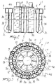
- the apparatus for performing the process according to the present invention comprises a heat exchanger, generally designated by the reference numerals 1 and 101 respectively in the two illustrated embodiments, which is meant to be immersed in the liquid 20 to be treated, said liquid being placed beforehand in a treatment vessel or vat 21, 102.
- the rotation rate of the turbine 5 and the shape of its vanes are designed so that the motion of the liquid 20 to be treated over the heat-exchange surface of the heat exchanger is a turbulent motion to ensure effective heat exchange between the heat-transferring fluid flowing in the tubes 3 and the liquid 20 to be treated.
- Each one of the tubes 3 lies on a vertical plane P defined by the axes of the descending portion 3a and of the ascending portion 3b of the related tube 3; said plane P forms a preset angle ⁇ with respect to the corresponding vertical radial plane R of the ideal cylindrical surfaces along which the axes of the portions 3a and 3b of the tubes 3 are arranged.
- Ducts 8 and 9, respectively for the intake and discharge of the heat-transferring fluid, are provided in said box-like manifold 6 on the face 6a that lies opposite to the face where the tubes 3 join.
- the inside of the box-like manifold 6 is divided by the partitions 7 into sections which, in a plan view, since there are at least two concentric sets, are arranged so that they are offset in a circumferential direction, so that each one of said sections acts as connection for the sections adjacent thereto. Therefore, for example, in figure 3 the reference numeral 10 designates the section that joins the sections 11 and 12. The two end sections are connected to the ducts 8 and 9 respectively.
- the lower end of the descending tube 3a is joined to the lower end of the ascending tube 3b through a rounded elbow 3c which protrudes slightly outward and inside which any deposit of condensate, however small, accumulates; in any case, said condensate is systematically removed and transferred outward by the current of the heat-transferring fluid itself.
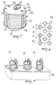
- the coils 4 are arranged so that they are mutually equidistant in order to form, in a sectional plane which is radial with respect to the axis 125, a sort of uniform grid. It has been observed that best efficiency is achieved by making the pitch between the coils 104 equal to their diameter "d" and by making the diagonal distance between said coils equal to half of said diameter "d" (figure 6).
- the plate 105 hereinafter termed upper plate, has manifolds 108 and 109 respectively for the intake and the discharge of the heat-transferring fluid, preferably steam, which is fed in the coils 104 of the tube bundle 103.
- the heat-transferring fluid preferably steam
- the upper plate 105 furthermore has couplings 110, located in mutually diametrically opposite positions, for coupling to an appropriate lifting element, not shown, which inserts the device into the vessel 102, containing the liquid to be treated, and removes it from said vessel.
- the dashed line indicates the position assumed by the exchanger 101 inside the vessel 102.
- the means for moving the liquid to be treated comprise an impeller 113 which is accommodated at the inlet 112 and is rotated by a motor 114, supported by the upper plate 105, by means of a transmission shaft 115 which is arranged coaxially to the tube bundle 103. Actuation of the impeller 113 draws the liquid to be treated from the bottom of the vessel 102 through the inlet 112 and produces a flow that strikes, with a preferably turbulent motion, the coils 104 of the tube bundle 103 in which the heat-transferring fluid for heating the tube bundle 103 flows.
- the liquid 20 to be treated is placed inside the vessel or treatment vat 21, 102 and the heat exchanger 1, 101 is immersed in the treatment liquid. While the heat exchanger 1, 101 is supplied with the heat-transferring fluid, the turbine 5 or impeller 113 is actuated, thus moving the liquid to be treated against the heat-exchange surface of the heat exchanger 1, 101.
- the actuation of the turbine 5 or impeller 113 in practice causes the cyclic flow of the liquid to be treated over the heat-exchange surface of the heat exchanger 1, 101 with a turbulent motion that ensures effective heat exchange between the heat-transferring fluid circulating inside the heat exchanger 1, 101 and the liquid 20 to be treated.
- the process and the apparatus for performing it, according to the invention differently from the conventional art, in which the liquid to be treated is heated by heating the walls of the vessel in which the liquid is contained and which is therefore heavily affected by the dimensions of the vessel, subjects the liquid placed in the vessel 21, 102 to heat treatment directly from the inside of the liquid to be treated.
- the heat-exchange surface is fully independent of the dimensions of the vessel containing the liquid to be treated, it is possible to perform heat treatments, i.e. heating processes but also cooling processes, at the rates and with the temperature changes required by a given production.
- the apparatus for performing the process according to the invention may also have multiple heat exchangers to be immersed in a same treatment vat according to the amount of liquid to be treated, as shown in figure 7.
- the process and the apparatus according to the invention have been conceived particularly to perform the heating process for coagulating milk in the making of heated-curd cheese, it may nonetheless be used advantageously to heat milk in the making of other kinds of cheese too, as well as for any heat treatment required in the making of dairy products in general.
- the process according to the invention may furthermore be used to heat or cool in a preset time not just milk, but other liquid food products as well, such as for example for the heat treatment of musts during fermentation in winemaking, or in other fields.
- the materials employed may be any according to the requirements and the state of the art.
Landscapes
- Engineering & Computer Science (AREA)
- Life Sciences & Earth Sciences (AREA)
- Wood Science & Technology (AREA)
- Zoology (AREA)
- Chemical & Material Sciences (AREA)
- Food Science & Technology (AREA)
- Polymers & Plastics (AREA)
- Physics & Mathematics (AREA)
- Thermal Sciences (AREA)
- Mechanical Engineering (AREA)
- General Engineering & Computer Science (AREA)
- Dairy Products (AREA)
Applications Claiming Priority (4)
| Application Number | Priority Date | Filing Date | Title |
|---|---|---|---|
| IT000005 IT1262579B (it) | 1993-01-25 | 1993-01-25 | Dispositivo scambiatore termico per la produzione casearia. |
| ITMO930005 | 1993-01-25 | ||
| ITMI932351 | 1993-11-04 | ||
| IT93MI002351A IT1266765B1 (it) | 1993-11-04 | 1993-11-04 | Procedimento ed apparecchiatura per il trattamento termico di liquidi alimentari,particolarmente per il riscaldamento del latte nella |
Publications (1)
| Publication Number | Publication Date |
|---|---|
| EP0620977A1 true EP0620977A1 (de) | 1994-10-26 |
Family
ID=26331060
Family Applications (1)
| Application Number | Title | Priority Date | Filing Date |
|---|---|---|---|
| EP94100942A Withdrawn EP0620977A1 (de) | 1993-01-25 | 1994-01-24 | Verfahren und Vorrichtung zur Wärmebehandlung von flüssigen Nahrungsmitteln, insbesondere zum Erhitzen der Milch bei der Herstellung von Milchprodukten |
Country Status (1)
| Country | Link |
|---|---|
| EP (1) | EP0620977A1 (de) |
Cited By (2)
| Publication number | Priority date | Publication date | Assignee | Title |
|---|---|---|---|---|
| WO1996004782A1 (en) * | 1994-08-12 | 1996-02-22 | Fermenta Engineering Llc | Complete self-contained multipurpose dairy processor unit for milk derivatives production |
| IT202000022384A1 (it) | 2020-09-23 | 2022-03-23 | Steel Tech Srl | Scambiatore per immersione a spirale |
Citations (4)
| Publication number | Priority date | Publication date | Assignee | Title |
|---|---|---|---|---|
| DE558198C (de) * | 1928-09-12 | 1932-09-05 | Alfred Pfleiderer Dr | Vorrichtung zum Erhitzen von Fluessigkeiten, insbesondere von Obstsaeften |
| US1914494A (en) * | 1931-10-20 | 1933-06-20 | Cherry Burrell Corp | Liquid heating and cooling apparatus |
| US2083837A (en) * | 1932-10-27 | 1937-06-15 | Pfaudler Co Inc | Liquid treating apparatus |
| US2084614A (en) * | 1934-05-31 | 1937-06-22 | Pfaudler Co Inc | Liquid treating apparatus |
-
1994
- 1994-01-24 EP EP94100942A patent/EP0620977A1/de not_active Withdrawn
Patent Citations (4)
| Publication number | Priority date | Publication date | Assignee | Title |
|---|---|---|---|---|
| DE558198C (de) * | 1928-09-12 | 1932-09-05 | Alfred Pfleiderer Dr | Vorrichtung zum Erhitzen von Fluessigkeiten, insbesondere von Obstsaeften |
| US1914494A (en) * | 1931-10-20 | 1933-06-20 | Cherry Burrell Corp | Liquid heating and cooling apparatus |
| US2083837A (en) * | 1932-10-27 | 1937-06-15 | Pfaudler Co Inc | Liquid treating apparatus |
| US2084614A (en) * | 1934-05-31 | 1937-06-22 | Pfaudler Co Inc | Liquid treating apparatus |
Cited By (3)
| Publication number | Priority date | Publication date | Assignee | Title |
|---|---|---|---|---|
| WO1996004782A1 (en) * | 1994-08-12 | 1996-02-22 | Fermenta Engineering Llc | Complete self-contained multipurpose dairy processor unit for milk derivatives production |
| US5916352A (en) * | 1994-08-12 | 1999-06-29 | Farmer Engineering Gesellschaft M.B.H. | Complete self-contained multipurpose dairy processor unit for milk derivatives production |
| IT202000022384A1 (it) | 2020-09-23 | 2022-03-23 | Steel Tech Srl | Scambiatore per immersione a spirale |
Similar Documents
| Publication | Publication Date | Title |
|---|---|---|
| JPH0419831B2 (de) | ||
| JP7245161B2 (ja) | 熱処理プラント及び熱処理プラントの運転方法 | |
| EP0620977A1 (de) | Verfahren und Vorrichtung zur Wärmebehandlung von flüssigen Nahrungsmitteln, insbesondere zum Erhitzen der Milch bei der Herstellung von Milchprodukten | |
| CN205897907U (zh) | 一种高效冷却装置 | |
| US4612086A (en) | Evaporators | |
| RU2127040C1 (ru) | Полностью автономная многофункциональная технологическая установка молочной фермы для производства молочных продуктов | |
| KR102391371B1 (ko) | 증기 멸균장치 | |
| EP3612733B1 (de) | Pumpe zum pumpen von wärmeempfindlichen flüssigkeiten | |
| CN119302340A (zh) | 一种应用于高粘度流体的旋转式灭菌装置 | |
| CN205279538U (zh) | 一种高效冷凝器 | |
| CN209333734U (zh) | 一种反应釜加热装置 | |
| EP3811018B1 (de) | Wärmetauscher | |
| CN216571557U (zh) | 一种应用于液体蒸发的切线逆流螺旋式蒸发器装置 | |
| CN222396981U (zh) | 一种浓缩果汁生产用杀菌装置 | |
| RU2034490C1 (ru) | Многоходовой трубчатый теплообменник | |
| CN214854041U (zh) | 一种管式杀菌机 | |
| CN219844896U (zh) | 一种杨梅汁的杀菌装置 | |
| CN220968156U (zh) | 萃取装置 | |
| CN212298918U (zh) | 一种电加热工艺制取医药纯蒸汽装置 | |
| CN212187860U (zh) | 一种vcm脱浆用的汽提塔 | |
| CN223525628U (zh) | 一种带有导流结构的弧形换热器 | |
| CN217346293U (zh) | 一种聚酯树脂制备用的热气冷却装置 | |
| RU138358U1 (ru) | Высокотемпературный пастеризатор бродского | |
| RU173194U1 (ru) | Пастеризатор бродского универсальный | |
| CN213021082U (zh) | 一种2-吡啶甲酸生产用冷却装置 |
Legal Events
| Date | Code | Title | Description |
|---|---|---|---|
| PUAI | Public reference made under article 153(3) epc to a published international application that has entered the european phase |
Free format text: ORIGINAL CODE: 0009012 |
|
| AK | Designated contracting states |
Kind code of ref document: A1 Designated state(s): AT CH DE FR LI NL |
|
| STAA | Information on the status of an ep patent application or granted ep patent |
Free format text: STATUS: THE APPLICATION IS DEEMED TO BE WITHDRAWN |
|
| 18D | Application deemed to be withdrawn |
Effective date: 19950427 |