EP0621071A1 - Procédé pour la séparation de gaz à basses températures - Google Patents
Procédé pour la séparation de gaz à basses températures Download PDFInfo
- Publication number
- EP0621071A1 EP0621071A1 EP94201021A EP94201021A EP0621071A1 EP 0621071 A1 EP0621071 A1 EP 0621071A1 EP 94201021 A EP94201021 A EP 94201021A EP 94201021 A EP94201021 A EP 94201021A EP 0621071 A1 EP0621071 A1 EP 0621071A1
- Authority
- EP
- European Patent Office
- Prior art keywords
- gases
- membrane
- temperature
- separation
- membranes
- Prior art date
- Legal status (The legal status is an assumption and is not a legal conclusion. Google has not performed a legal analysis and makes no representation as to the accuracy of the status listed.)
- Granted
Links
- 239000007789 gas Substances 0.000 title claims abstract description 47
- 238000000034 method Methods 0.000 title claims abstract description 25
- 238000000926 separation method Methods 0.000 title claims description 18
- 239000012528 membrane Substances 0.000 claims abstract description 61
- 239000000203 mixture Substances 0.000 claims abstract description 8
- 238000007873 sieving Methods 0.000 claims abstract description 6
- IJGRMHOSHXDMSA-UHFFFAOYSA-N Atomic nitrogen Chemical compound N#N IJGRMHOSHXDMSA-UHFFFAOYSA-N 0.000 claims description 16
- 239000002808 molecular sieve Substances 0.000 claims description 13
- URGAHOPLAPQHLN-UHFFFAOYSA-N sodium aluminosilicate Chemical compound [Na+].[Al+3].[O-][Si]([O-])=O.[O-][Si]([O-])=O URGAHOPLAPQHLN-UHFFFAOYSA-N 0.000 claims description 13
- QVGXLLKOCUKJST-UHFFFAOYSA-N atomic oxygen Chemical compound [O] QVGXLLKOCUKJST-UHFFFAOYSA-N 0.000 claims description 11
- 239000001301 oxygen Substances 0.000 claims description 11
- 229910052760 oxygen Inorganic materials 0.000 claims description 11
- XKRFYHLGVUSROY-UHFFFAOYSA-N Argon Chemical compound [Ar] XKRFYHLGVUSROY-UHFFFAOYSA-N 0.000 claims description 10
- 238000009835 boiling Methods 0.000 claims description 9
- 229910052757 nitrogen Inorganic materials 0.000 claims description 8
- OKTJSMMVPCPJKN-UHFFFAOYSA-N Carbon Chemical compound [C] OKTJSMMVPCPJKN-UHFFFAOYSA-N 0.000 claims description 6
- 229910052799 carbon Inorganic materials 0.000 claims description 6
- 229910052786 argon Inorganic materials 0.000 claims description 5
- 230000005494 condensation Effects 0.000 claims 1
- 238000009833 condensation Methods 0.000 claims 1
- 238000005057 refrigeration Methods 0.000 claims 1
- 230000035699 permeability Effects 0.000 description 22
- 230000008569 process Effects 0.000 description 10
- 238000001179 sorption measurement Methods 0.000 description 7
- 230000004913 activation Effects 0.000 description 6
- 239000012466 permeate Substances 0.000 description 6
- 239000011148 porous material Substances 0.000 description 6
- 238000009792 diffusion process Methods 0.000 description 5
- 239000012535 impurity Substances 0.000 description 5
- 239000007788 liquid Substances 0.000 description 5
- 239000002184 metal Substances 0.000 description 5
- CURLTUGMZLYLDI-UHFFFAOYSA-N Carbon dioxide Chemical compound O=C=O CURLTUGMZLYLDI-UHFFFAOYSA-N 0.000 description 4
- 229920000642 polymer Polymers 0.000 description 4
- UFHFLCQGNIYNRP-UHFFFAOYSA-N Hydrogen Chemical compound [H][H] UFHFLCQGNIYNRP-UHFFFAOYSA-N 0.000 description 3
- 238000001816 cooling Methods 0.000 description 3
- 230000000694 effects Effects 0.000 description 3
- 239000011521 glass Substances 0.000 description 3
- 239000012510 hollow fiber Substances 0.000 description 3
- 239000001257 hydrogen Substances 0.000 description 3
- 229910052739 hydrogen Inorganic materials 0.000 description 3
- 239000000463 material Substances 0.000 description 3
- 238000005259 measurement Methods 0.000 description 3
- 239000000047 product Substances 0.000 description 3
- 229910002092 carbon dioxide Inorganic materials 0.000 description 2
- 238000005229 chemical vapour deposition Methods 0.000 description 2
- 238000010438 heat treatment Methods 0.000 description 2
- 238000004519 manufacturing process Methods 0.000 description 2
- VNWKTOKETHGBQD-UHFFFAOYSA-N methane Chemical compound C VNWKTOKETHGBQD-UHFFFAOYSA-N 0.000 description 2
- 238000012544 monitoring process Methods 0.000 description 2
- 229920005597 polymer membrane Polymers 0.000 description 2
- 238000002360 preparation method Methods 0.000 description 2
- MWWATHDPGQKSAR-UHFFFAOYSA-N propyne Chemical compound CC#C MWWATHDPGQKSAR-UHFFFAOYSA-N 0.000 description 2
- 230000032258 transport Effects 0.000 description 2
- MYMOFIZGZYHOMD-UHFFFAOYSA-N Dioxygen Chemical compound O=O MYMOFIZGZYHOMD-UHFFFAOYSA-N 0.000 description 1
- 102000003939 Membrane transport proteins Human genes 0.000 description 1
- 108090000301 Membrane transport proteins Proteins 0.000 description 1
- 239000012494 Quartz wool Substances 0.000 description 1
- 238000013459 approach Methods 0.000 description 1
- 239000001569 carbon dioxide Substances 0.000 description 1
- 238000003763 carbonization Methods 0.000 description 1
- 239000012159 carrier gas Substances 0.000 description 1
- 230000008859 change Effects 0.000 description 1
- 238000005234 chemical deposition Methods 0.000 description 1
- 238000004821 distillation Methods 0.000 description 1
- 239000000835 fiber Substances 0.000 description 1
- 239000011261 inert gas Substances 0.000 description 1
- 230000014759 maintenance of location Effects 0.000 description 1
- 230000007246 mechanism Effects 0.000 description 1
- 230000009061 membrane transport Effects 0.000 description 1
- 239000012982 microporous membrane Substances 0.000 description 1
- 238000012986 modification Methods 0.000 description 1
- 230000004048 modification Effects 0.000 description 1
- 238000004382 potting Methods 0.000 description 1
- 239000002243 precursor Substances 0.000 description 1
- 238000011045 prefiltration Methods 0.000 description 1
- 238000010992 reflux Methods 0.000 description 1
- 230000002277 temperature effect Effects 0.000 description 1
- 238000012360 testing method Methods 0.000 description 1
- 230000007723 transport mechanism Effects 0.000 description 1
- XLYOFNOQVPJJNP-UHFFFAOYSA-N water Chemical compound O XLYOFNOQVPJJNP-UHFFFAOYSA-N 0.000 description 1
Images

Classifications
-
- B—PERFORMING OPERATIONS; TRANSPORTING
- B01—PHYSICAL OR CHEMICAL PROCESSES OR APPARATUS IN GENERAL
- B01D—SEPARATION
- B01D71/00—Semi-permeable membranes for separation processes or apparatus characterised by the material; Manufacturing processes specially adapted therefor
- B01D71/02—Inorganic material
- B01D71/028—Molecular sieves
-
- B—PERFORMING OPERATIONS; TRANSPORTING
- B01—PHYSICAL OR CHEMICAL PROCESSES OR APPARATUS IN GENERAL
- B01D—SEPARATION
- B01D53/00—Separation of gases or vapours; Recovering vapours of volatile solvents from gases; Chemical or biological purification of waste gases, e.g. engine exhaust gases, smoke, fumes, flue gases, aerosols
- B01D53/22—Separation of gases or vapours; Recovering vapours of volatile solvents from gases; Chemical or biological purification of waste gases, e.g. engine exhaust gases, smoke, fumes, flue gases, aerosols by diffusion
-
- B—PERFORMING OPERATIONS; TRANSPORTING
- B01—PHYSICAL OR CHEMICAL PROCESSES OR APPARATUS IN GENERAL
- B01D—SEPARATION
- B01D53/00—Separation of gases or vapours; Recovering vapours of volatile solvents from gases; Chemical or biological purification of waste gases, e.g. engine exhaust gases, smoke, fumes, flue gases, aerosols
- B01D53/22—Separation of gases or vapours; Recovering vapours of volatile solvents from gases; Chemical or biological purification of waste gases, e.g. engine exhaust gases, smoke, fumes, flue gases, aerosols by diffusion
- B01D53/228—Separation of gases or vapours; Recovering vapours of volatile solvents from gases; Chemical or biological purification of waste gases, e.g. engine exhaust gases, smoke, fumes, flue gases, aerosols by diffusion characterised by specific membranes
-
- B—PERFORMING OPERATIONS; TRANSPORTING
- B01—PHYSICAL OR CHEMICAL PROCESSES OR APPARATUS IN GENERAL
- B01D—SEPARATION
- B01D67/00—Processes specially adapted for manufacturing semi-permeable membranes for separation processes or apparatus
- B01D67/0039—Inorganic membrane manufacture
- B01D67/0072—Inorganic membrane manufacture by deposition from the gaseous phase, e.g. sputtering, CVD, PVD
-
- B—PERFORMING OPERATIONS; TRANSPORTING
- B01—PHYSICAL OR CHEMICAL PROCESSES OR APPARATUS IN GENERAL
- B01D—SEPARATION
- B01D71/00—Semi-permeable membranes for separation processes or apparatus characterised by the material; Manufacturing processes specially adapted therefor
- B01D71/02—Inorganic material
- B01D71/021—Carbon
-
- B—PERFORMING OPERATIONS; TRANSPORTING
- B01—PHYSICAL OR CHEMICAL PROCESSES OR APPARATUS IN GENERAL
- B01D—SEPARATION
- B01D2323/00—Details relating to membrane preparation
- B01D2323/08—Specific temperatures applied
- B01D2323/082—Cooling
Definitions
- the present invention relates to the separation of gases at low temperatures. More particularly, the invention relates to the use of carbon molecular sieve membranes for the separation of gases at temperatures approaching those at which gases liquefy.
- Carbon molecular sieve membranes are an example of microporous membranes (pore size less than 20 Angstroms), which separate gas molecules on the basis of their different diameters (molecular sieving).
- the mechanism for such membrane transport is based on a combination of adsorption within and activated diffusion along the pore length.
- Studies of gas permeation through microporous membranes show selectivities much greater than would be expected from Knudsen diffusion - the predominant bulk process in micropores. Therefore, the process can be seen to occur predominantly through hopping between adsorption sites.
- the permeation rate will be proportional to the product of the local gradient of the concentration of gas molecules adsorbed on the pore and the effective diffusion coefficient (D) at that point in the pore.
- the temperature dependence of the permeability in membranes will depend on the temperature dependence of the activated diffusion coefficient D, and that of the extent of adsorption. While adsorption isotherms show that the extent of adsorption for most gases on most materials will increase with a drop in temperature, the activated diffusion coefficient often drops much more drastically, leading to a net drop in permeability with the drop in temperature. This is particularly the case for glassy polymers where the process for activated transport involves some movement of polymer segments to allow movement of gas molecules through interconnected free volumes. Even though some polymer membranes are known to show an increase in selectivity with decrease in temperatures, they suffer a disastrous loss of permeability even for the faster member of a gas pair as the membrane approaches the temperature where all polymer motion is frozen out.
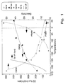
- Fig. 1 shows that for polytrimethylsilyl propyne (PTMSP), one of the more state of the art membranes, the permeability drops drastically below -20°C.
- PTMSP polytrimethylsilyl propyne
- US 4,398,926 teaches the separation of hydrogen from a high-pressure stream, using a permeable membrane.
- US 4,681,612 deals with the separation of landfill gas, and provides for the removal of impurities and carbon dioxide in a cryogenic column. Methane is then separated bya a membrane process. The temperature in the membrane is 80°F.
- US 4,595,405 again, combines a cryogenic separation unit and a membrane separation unit. The membrane unit is operated with gas at or near ambient temperature.
- the inventors believe that the reason for this unexpected behavior resides in the structure of the molecular sieve membrane and in the different transport mechanism therein as compared, e.g., with glassy polymers membranes.
- the molecular sieve membrane can be of any suitable type, e.g., carbon molecular sieve membranes (CMSM) or glass molecular sieve membranes (GMSM).
- CMSM carbon molecular sieve membranes
- GMSM glass molecular sieve membranes
- the invention also encompasses the use of microporous molecular sieving membranes to separate between gaseous molecules of different diameter at sub-ambient temperatures, resulting in much greater selectivities than can be achieved at ambient temperature. Because molecular sieve membranes such as GMSM and CMSM can operate at or near the temperatures of air liquefaction, they will be referred to hereinafter as a "cryomembrane”.
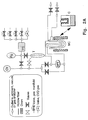
- FIG. 2 A setup for operating according to one embodiment of the invention is illustrated in Fig. 2.
- this setupe is provided only by way of example and is not intended to limit the invention in any way.
- modular devices of various geometries e.g., hollow fiber, plate and frame, spiral wound
- a commercial cryogenic cold box with local heat exchanger and heater networks to maintain a local temperature within the module.
- T - Trap for liquid chemical vapor deposition material carried by a gas CV - Calibrated volume; FC - Flow controller; FM - Flow meter; DPT - Differential pressure transducer; Pg - Pressure gauge; Pr - Pressure regulator BPR - Back pressure regulator; C - Cryostat; MC - Membrane cell.
- the membrane cell (M) is placed inside an oven during manufacture, or in a cryostat (C) during low temperature permeability measurements.
- the gases used for tailoring the pore size and for subsequent permeation measurements are fed from a manifold on which a flow controller (FC) and pressure gauge allow metering of the absolute amounts fed to the membrane cell.
- FC flow controller
- pressure gauge allow metering of the absolute amounts fed to the membrane cell.
- CVD chemical deposition of vapor
- T liquid trap
- a carrier gas usually N2
- the permeability of the membrane is measured by monitoring the change with time in the feed-side pressure volume product (dPV/dt) as given by the pressure gauge (Pg) and the calibrated volume (CV), while simultaneously monitoring the transmembrane pressure drop with the transducer DPT.
- Fig. 2B the gas flow within the membrane cell is illustrated.
- Numeral 1 indicated the shell entrance
- numeral 2 the shell exit
- numeral 3 the bore entrance/exit.
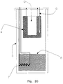
- Fig. 2C shows a cryostat which can be used in the system of Fig. 2A, which is described in detail below, with reference to Example 1.
- the membrane module was made by potting hollow fiber carbon molecular sieve membranes in a U-shaped glass tube.
- the module has connections for introducing a feed gas, and removing separate a reject streams (nonpermeate) and permeate streams.
- the membranes were prepared according to the methods described in USP 4,685,940 and GB 2,207,666. This membrane preparation involved the following steps:
- the method comprises producing a CMSM having a permeability greater than 100 L/M2H-atm and a selectivity greater than 4.0 at room temperature, and then cooling the CMSM to cryogenic temperatures and separating a mixture of gases therewith.
- the gas mixture may be fed from the shell or bore side. If the gas mixture is fed in the shell side, a preferred method is to feed it down the center tube, where impurities can be precondensed in a packed bed contained in the center tube, and the feed gas splits and feeds both arms of the U tube simultaneously. The reject is recombined in a reject manifold and led away from the module.
- the module can be cooled by placing it in any controlled subzero environment, such as a commercial cold box.
- the pressure difference to drive the permeation process can be applied by providing a pressurized feed while the permeate is kept at ambient pressures.
- the gas can be provided at ambient pressures while drawing a vacuum or using a sweep gas on the permeate side.
- any combination of these methods of effecting a pressure difference between the two sides of the membrane can be used.
- One particular embodiment would be to use as feed the vapor in equilibrium with a low-boiling gas such as oxygen, or an oxygen/argon mixture, such that at the temperature of operation, the vapor pressure of the low-boiling gas would be very high.
- a low-boiling gas such as oxygen, or an oxygen/argon mixture
- FIG. 1 illustrates how the vapor pressure of oxygen varies with temperature.
- the permeate could be maintained at a high enough pressure to allow recompression and liquefaction of the permeate with a moderate outlay of energy, if the permeate stream were of value.
- a module was prepared by taking hollow carbon membrane potted in a U-shaped glass housing, as shown in Fig. 2B. It was placed in an apparatus (Fig. 2A) for measuring permeability in which activation steps could be effected, as described in GB 2,207,666 and summarized in Table 1. The permeabilities were measured on the same apparatus with the gases fed on the shell side of the membrane through the center of the U tube. A plug of quartz wool was inserted in the center tube to serve as a prefilter on which to adsorb the impurities.
- the cryostat was enclosed in a cryostat designed to maintain the module at constant temperatures ranging from 77°K to RT.
- the cryostat is illustrated in Fig. 2C.
- the cryostat consists of a metal block, 4, suspended in a Dewar flask 5 in which liquid nitrogen 6 has been introduced to a level near but not touching the bottom surface of the metal block.
- a heater 7 is immersed in the liquid nitrogen for the purpose of boiling nitrogen to generate a cold nitrogen vapor which can rise and cool the metal block.
- a heating element is wrapped around the metal block to allow local heating of the block for purposes of moderating the cooling effects of the nitrogen vapor or for quickly moving to a new operating temperature higher than the previous one.
- thermocouple 8 is inserted into a hole in the block and its signal is fed as the input into a temperature controller.
- the temperature controller controls the current to the cooling heater to maintain a particular setpoint.
- This arrangement allows operation of the membrane at temperatures between ambient and the boiling point of nitrogen (77 °K).
- an arrangement is made for adsorbing low vapor pressure impurities in the feed gas (e.g., water vapor and CO2), prior to introducing the feed gas into the membrane itself.
- the membrane was inserted into a slot 9 in the center of the metal block of the cryostat and its temperature systematically was varied between ambient and -176°C.
- the results are plotted in Fig. 1, where the permeability is shown on the left axis and the selectivity is shown on the right axis.
- the permselectivity of the PTMSP membrane is plotted on the same axis as a function of the temperature. The retention of the permeability at low temperatures for the CMSM membrane as compared to the PTMSP membrane is striking.
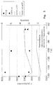
- a membrane was prepared as described in Example 1 but with a somewhat different schedule of activation and CVD, as detailed in Table 2.
- the gas feed was fed into the center tube where impurities were adsorbed as the gas cooled, at the bottom the gas flow split to travel up to two legs of the U tube and was conducted away through a reject manifold at the exit of the U tube at the top.
- the invention leads to unexpected results, enabling substantially improved separation results, in a manner which was not possible according to prior art methods and devices.
- Many modifications can of course be made in the various membranes, devices utilizing them and processes which incorporate the devices, and many different separation processes can be carried out, using different gases, all without exceeding the scope of the invention.
Landscapes
- Chemical & Material Sciences (AREA)
- Chemical Kinetics & Catalysis (AREA)
- Inorganic Chemistry (AREA)
- Engineering & Computer Science (AREA)
- Analytical Chemistry (AREA)
- General Chemical & Material Sciences (AREA)
- Oil, Petroleum & Natural Gas (AREA)
- Manufacturing & Machinery (AREA)
- Separation Using Semi-Permeable Membranes (AREA)
Applications Claiming Priority (2)
| Application Number | Priority Date | Filing Date | Title |
|---|---|---|---|
| IL10544293A IL105442A (en) | 1993-04-19 | 1993-04-19 | Method for the separation of gases at low temperatures |
| IL10544293 | 1993-04-19 |
Publications (2)
| Publication Number | Publication Date |
|---|---|
| EP0621071A1 true EP0621071A1 (fr) | 1994-10-26 |
| EP0621071B1 EP0621071B1 (fr) | 1999-11-03 |
Family
ID=11064749
Family Applications (1)
| Application Number | Title | Priority Date | Filing Date |
|---|---|---|---|
| EP94201021A Expired - Lifetime EP0621071B1 (fr) | 1993-04-19 | 1994-04-14 | Procédé pour la séparation de gaz à basses températures |
Country Status (7)
| Country | Link |
|---|---|
| US (1) | US5649996A (fr) |
| EP (1) | EP0621071B1 (fr) |
| JP (1) | JPH06319934A (fr) |
| AU (1) | AU669056B2 (fr) |
| CA (1) | CA2121666A1 (fr) |
| DE (1) | DE69421438D1 (fr) |
| IL (1) | IL105442A (fr) |
Cited By (4)
| Publication number | Priority date | Publication date | Assignee | Title |
|---|---|---|---|---|
| WO1996022260A3 (fr) * | 1995-01-16 | 1996-10-24 | Carbon Membranes Ltd | Separation d'hydrocarbures lineaires d'hydrocarbures ramifies |
| US5914434A (en) * | 1995-01-16 | 1999-06-22 | Carbon Membranes, Ltd. | Separation of linear from branched hydrocarbons using a carbon membrane |
| CN1069845C (zh) * | 1996-06-21 | 2001-08-22 | 付文兵 | 流体输运法 |
| US8763610B2 (en) | 2006-07-26 | 2014-07-01 | Klaus Schmidt | Retention of noble gases in the exhaled air of ventilated patients by membrane separation |
Families Citing this family (15)
| Publication number | Priority date | Publication date | Assignee | Title |
|---|---|---|---|---|
| JP2001510395A (ja) * | 1997-01-23 | 2001-07-31 | カーボン メンブレインズ リミテッド | モレキュラーシーブ膜を用いる過フッ化化合物およびヒドロフルオロカーボンガスの回収 |
| EP1118378A1 (fr) * | 1998-08-28 | 2001-07-25 | Toray Industries, Inc. | Film transmissif, condensateur electrolytique, procede de preparation de film de zeolite, film de zeolite de type mfi et procede de separation |
| DE19849216A1 (de) | 1998-10-26 | 2000-04-27 | Andreas Noack | Verfahren und Vorrichtung zur Trennung von Fluidgemischen (Thermomembranverfahren) |
| US6503295B1 (en) * | 2000-09-20 | 2003-01-07 | Chevron U.S.A. Inc. | Gas separations using mixed matrix membranes |
| WO2004033061A2 (fr) * | 2002-10-04 | 2004-04-22 | The Regents Of The University Of California | Dispositif permettant de produire et de separer le fluor |
| US7238266B2 (en) * | 2002-12-06 | 2007-07-03 | Mks Instruments, Inc. | Method and apparatus for fluorine generation and recirculation |
| US7306647B2 (en) * | 2004-11-19 | 2007-12-11 | Chevron U.S.A. Inc. | Mixed matrix membrane with mesoporous particles and methods for making and using the same |
| WO2006119418A2 (fr) * | 2005-05-03 | 2006-11-09 | Kalechofsky, Neal | Procede et appareil de refroidissement en continu d'echantillons a ultra basse temperature |
| EP2501460B1 (fr) | 2009-11-16 | 2023-06-07 | Kent Knaebel & Associates, Inc. | Système d'adsorption multistades pour une séparation d'un mélange de gaz |
| WO2011130087A2 (fr) | 2010-04-13 | 2011-10-20 | Carrier Corporation | Systèmes et procédés pour atmosphère contrôlée |
| US9610550B2 (en) * | 2012-03-28 | 2017-04-04 | Rasirc, Inc. | Method of delivering a process gas from a multi-component solution |
| US10076620B2 (en) | 2012-12-22 | 2018-09-18 | Dmf Medical Incorporated | Anesthetic circuit having a hollow fiber membrane |
| US9410191B2 (en) | 2014-05-13 | 2016-08-09 | Rasirc, Inc. | Method and system for decontaminating materials |
| US10150048B2 (en) | 2014-10-23 | 2018-12-11 | Rasirc, Inc. | Method, system, and device for delivery of process gas |
| JP7580598B2 (ja) * | 2021-06-03 | 2024-11-11 | 日本碍子株式会社 | 混合ガス分離方法および混合ガス分離装置 |
Citations (6)
| Publication number | Priority date | Publication date | Assignee | Title |
|---|---|---|---|---|
| EP0362898A2 (fr) * | 1988-10-07 | 1990-04-11 | Yeda Research And Development Company Limited | Dispositif et procédé pour séparer des gaz |
| JPH02307805A (ja) * | 1989-05-22 | 1990-12-21 | Nippon Sanso Kk | 酸素の製造装置 |
| EP0410845A1 (fr) * | 1989-07-17 | 1991-01-30 | L'air Liquide, Societe Anonyme Pour L'etude Et L'exploitation Des Procedes Georges Claude | Récupération de carbone dioxide provenant d'une installation en utilisant des membranes |
| EP0428052A2 (fr) * | 1989-11-14 | 1991-05-22 | Air Products And Chemicals, Inc. | SÀ©paration de gaz à l'aide de membranes adsorbantes |
| EP0460512A1 (fr) * | 1990-06-05 | 1991-12-11 | Mobil Oil Corporation | Membrane en tamis moléculaire cristallin |
| WO1992013628A2 (fr) * | 1991-01-30 | 1992-08-20 | The Dow Chemical Company | Separations des gaz effectuees a l'aide de membranes polymeres vitreuses a des temperatures inferieures a la temperature ambiante |
Family Cites Families (16)
| Publication number | Priority date | Publication date | Assignee | Title |
|---|---|---|---|---|
| US2650670A (en) * | 1950-01-26 | 1953-09-01 | Gulf Research Development Co | Molecular filtration |
| US2924630A (en) * | 1957-06-28 | 1960-02-09 | Union Oil Co | Fluid diffusion fractionation |
| US3149775A (en) * | 1961-12-13 | 1964-09-22 | Gen Electric | Vacuum system |
| US3511031A (en) * | 1968-03-19 | 1970-05-12 | Little Inc A | Apparatus for removing water vapor from gases |
| JPS515499A (en) * | 1974-07-03 | 1976-01-17 | Hitachi Ltd | Hoshaseikigasuno bunrikaishusochi |
| US4398926A (en) * | 1982-04-23 | 1983-08-16 | Union Carbide Corporation | Enhanced hydrogen recovery from low purity gas streams |
| US5127925A (en) * | 1982-12-13 | 1992-07-07 | Allied-Signal Inc. | Separation of gases by means of mixed matrix membranes |
| US4685940A (en) * | 1984-03-12 | 1987-08-11 | Abraham Soffer | Separation device |
| US4681612A (en) * | 1984-05-31 | 1987-07-21 | Koch Process Systems, Inc. | Process for the separation of landfill gas |
| US4595405A (en) * | 1984-12-21 | 1986-06-17 | Air Products And Chemicals, Inc. | Process for the generation of gaseous and/or liquid nitrogen |
| GB2207666B (en) * | 1987-08-06 | 1992-03-18 | Israel Atomic Energy Comm | Carbon membranes and process for producing them |
| US4841732A (en) * | 1987-12-28 | 1989-06-27 | Sarcia Domenico S | System and apparatus for producing and storing liquid gases |
| US4881953A (en) * | 1988-09-15 | 1989-11-21 | Union Carbide Corporation | Prevention of membrane degradation |
| US5342431A (en) * | 1989-10-23 | 1994-08-30 | Wisconsin Alumni Research Foundation | Metal oxide membranes for gas separation |
| US5104425A (en) * | 1989-11-14 | 1992-04-14 | Air Products And Chemicals, Inc. | Gas separation by adsorbent membranes |
| US5069794A (en) * | 1990-06-05 | 1991-12-03 | Mobil Oil Corp. | Separation of mixture components over membrane composed of a pure molecular sieve |
-
1993
- 1993-04-19 IL IL10544293A patent/IL105442A/en not_active IP Right Cessation
-
1994
- 1994-04-14 EP EP94201021A patent/EP0621071B1/fr not_active Expired - Lifetime
- 1994-04-14 DE DE69421438T patent/DE69421438D1/de not_active Expired - Lifetime
- 1994-04-19 AU AU60574/94A patent/AU669056B2/en not_active Ceased
- 1994-04-19 JP JP6080155A patent/JPH06319934A/ja active Pending
- 1994-04-19 CA CA002121666A patent/CA2121666A1/fr not_active Abandoned
-
1995
- 1995-10-23 US US08/546,618 patent/US5649996A/en not_active Expired - Fee Related
Patent Citations (6)
| Publication number | Priority date | Publication date | Assignee | Title |
|---|---|---|---|---|
| EP0362898A2 (fr) * | 1988-10-07 | 1990-04-11 | Yeda Research And Development Company Limited | Dispositif et procédé pour séparer des gaz |
| JPH02307805A (ja) * | 1989-05-22 | 1990-12-21 | Nippon Sanso Kk | 酸素の製造装置 |
| EP0410845A1 (fr) * | 1989-07-17 | 1991-01-30 | L'air Liquide, Societe Anonyme Pour L'etude Et L'exploitation Des Procedes Georges Claude | Récupération de carbone dioxide provenant d'une installation en utilisant des membranes |
| EP0428052A2 (fr) * | 1989-11-14 | 1991-05-22 | Air Products And Chemicals, Inc. | SÀ©paration de gaz à l'aide de membranes adsorbantes |
| EP0460512A1 (fr) * | 1990-06-05 | 1991-12-11 | Mobil Oil Corporation | Membrane en tamis moléculaire cristallin |
| WO1992013628A2 (fr) * | 1991-01-30 | 1992-08-20 | The Dow Chemical Company | Separations des gaz effectuees a l'aide de membranes polymeres vitreuses a des temperatures inferieures a la temperature ambiante |
Non-Patent Citations (1)
| Title |
|---|
| PATENT ABSTRACTS OF JAPAN vol. 015, no. 096 (C - 0812) 7 March 1991 (1991-03-07) * |
Cited By (4)
| Publication number | Priority date | Publication date | Assignee | Title |
|---|---|---|---|---|
| WO1996022260A3 (fr) * | 1995-01-16 | 1996-10-24 | Carbon Membranes Ltd | Separation d'hydrocarbures lineaires d'hydrocarbures ramifies |
| US5914434A (en) * | 1995-01-16 | 1999-06-22 | Carbon Membranes, Ltd. | Separation of linear from branched hydrocarbons using a carbon membrane |
| CN1069845C (zh) * | 1996-06-21 | 2001-08-22 | 付文兵 | 流体输运法 |
| US8763610B2 (en) | 2006-07-26 | 2014-07-01 | Klaus Schmidt | Retention of noble gases in the exhaled air of ventilated patients by membrane separation |
Also Published As
| Publication number | Publication date |
|---|---|
| IL105442A (en) | 1996-01-19 |
| DE69421438D1 (de) | 1999-12-09 |
| JPH06319934A (ja) | 1994-11-22 |
| IL105442A0 (en) | 1993-08-18 |
| AU6057494A (en) | 1994-10-20 |
| CA2121666A1 (fr) | 1994-10-20 |
| US5649996A (en) | 1997-07-22 |
| AU669056B2 (en) | 1996-05-23 |
| EP0621071B1 (fr) | 1999-11-03 |
Similar Documents
| Publication | Publication Date | Title |
|---|---|---|
| EP0621071B1 (fr) | Procédé pour la séparation de gaz à basses températures | |
| Way et al. | Hollow fiber inorganic membranes for gas separations | |
| US5858065A (en) | Process and system for separation and recovery of perfluorocompound gases | |
| Koresh et al. | Mechanism of permeation through molecular-sieve carbon membrane. Part 1.—The effect of adsorption and the dependence on pressure | |
| Shelekhin et al. | Adsorption, permeation, and diffusion of gases in microporous membranes. II. Permeation of gases in microporous glass membranes | |
| Kiyono et al. | Effect of pyrolysis atmosphere on separation performance of carbon molecular sieve membranes | |
| US8486179B2 (en) | Method for producing carbon molecular sieve membranes in controlled atmospheres | |
| Favvas et al. | Characterization of highly selective microporous carbon hollow fiber membranes prepared from a commercial co-polyimide precursor | |
| US3250080A (en) | Method of separating gaseous mixtures by diffusion and fractionation | |
| US4894068A (en) | Process for capturing nitrogen from air using gas separation membranes | |
| US3246449A (en) | Recovery of helium | |
| CN102123780B (zh) | 从气态化合物的混合物中回收气态组分 | |
| De Lange et al. | Permeation and separation studies on microporous sol-gel modified ceramic membranes | |
| CA2029484C (fr) | Separation de gaz a l'aide de membranes absorbantes | |
| JP7262454B2 (ja) | 第13族金属を含有する炭素分子ふるい膜およびそれらを作製する方法 | |
| EP0326360A2 (fr) | Procédé de separation sélectif de vapeur d'eau d'un mélange de gaz | |
| IE970031A1 (en) | An improved process and system for separation and recovery¹of perfluorocompound gases | |
| US20150290596A1 (en) | Carbon molecular sieve membranes for nitrogen/methane separation | |
| KR20210005011A (ko) | 탄소 분자체 막의 향상된 제조 방법 | |
| JPH04227036A (ja) | 住宅用の炉の空気取入れシステム | |
| US5162301A (en) | Separation of paramagnetic and diamagnetic gases | |
| JP2005161187A (ja) | ガス分離回収装置及び分離回収方法 | |
| Kryuchkov et al. | Membrane air separation process simulation: Insight in modelling approach based on ideal and mixed permeance values | |
| KR20210005010A (ko) | 탄소 분자체 막의 향상된 제조 방법 | |
| Kiyono | Carbon molecular sieve membranes for natural gas separations |
Legal Events
| Date | Code | Title | Description |
|---|---|---|---|
| PUAI | Public reference made under article 153(3) epc to a published international application that has entered the european phase |
Free format text: ORIGINAL CODE: 0009012 |
|
| AK | Designated contracting states |
Kind code of ref document: A1 Designated state(s): BE DE ES FR GB IT NL SE |
|
| 17P | Request for examination filed |
Effective date: 19950203 |
|
| 17Q | First examination report despatched |
Effective date: 19960621 |
|
| GRAG | Despatch of communication of intention to grant |
Free format text: ORIGINAL CODE: EPIDOS AGRA |
|
| GRAG | Despatch of communication of intention to grant |
Free format text: ORIGINAL CODE: EPIDOS AGRA |
|
| GRAG | Despatch of communication of intention to grant |
Free format text: ORIGINAL CODE: EPIDOS AGRA |
|
| GRAH | Despatch of communication of intention to grant a patent |
Free format text: ORIGINAL CODE: EPIDOS IGRA |
|
| GRAH | Despatch of communication of intention to grant a patent |
Free format text: ORIGINAL CODE: EPIDOS IGRA |
|
| GRAA | (expected) grant |
Free format text: ORIGINAL CODE: 0009210 |
|
| AK | Designated contracting states |
Kind code of ref document: B1 Designated state(s): BE DE ES FR GB IT NL SE |
|
| PG25 | Lapsed in a contracting state [announced via postgrant information from national office to epo] |
Ref country code: SE Free format text: THE PATENT HAS BEEN ANNULLED BY A DECISION OF A NATIONAL AUTHORITY Effective date: 19991103 Ref country code: NL Free format text: LAPSE BECAUSE OF FAILURE TO SUBMIT A TRANSLATION OF THE DESCRIPTION OR TO PAY THE FEE WITHIN THE PRESCRIBED TIME-LIMIT Effective date: 19991103 Ref country code: IT Free format text: LAPSE BECAUSE OF FAILURE TO SUBMIT A TRANSLATION OF THE DESCRIPTION OR TO PAY THE FEE WITHIN THE PRESCRIBED TIME-LIMIT;WARNING: LAPSES OF ITALIAN PATENTS WITH EFFECTIVE DATE BEFORE 2007 MAY HAVE OCCURRED AT ANY TIME BEFORE 2007. THE CORRECT EFFECTIVE DATE MAY BE DIFFERENT FROM THE ONE RECORDED. Effective date: 19991103 Ref country code: ES Free format text: THE PATENT HAS BEEN ANNULLED BY A DECISION OF A NATIONAL AUTHORITY Effective date: 19991103 Ref country code: BE Free format text: LAPSE BECAUSE OF FAILURE TO SUBMIT A TRANSLATION OF THE DESCRIPTION OR TO PAY THE FEE WITHIN THE PRESCRIBED TIME-LIMIT Effective date: 19991103 |
|
| REF | Corresponds to: |
Ref document number: 69421438 Country of ref document: DE Date of ref document: 19991209 |
|
| PG25 | Lapsed in a contracting state [announced via postgrant information from national office to epo] |
Ref country code: DE Free format text: LAPSE BECAUSE OF FAILURE TO SUBMIT A TRANSLATION OF THE DESCRIPTION OR TO PAY THE FEE WITHIN THE PRESCRIBED TIME-LIMIT Effective date: 20000204 |
|
| ET | Fr: translation filed | ||
| NLV1 | Nl: lapsed or annulled due to failure to fulfill the requirements of art. 29p and 29m of the patents act | ||
| PLBE | No opposition filed within time limit |
Free format text: ORIGINAL CODE: 0009261 |
|
| STAA | Information on the status of an ep patent application or granted ep patent |
Free format text: STATUS: NO OPPOSITION FILED WITHIN TIME LIMIT |
|
| 26N | No opposition filed | ||
| REG | Reference to a national code |
Ref country code: GB Ref legal event code: IF02 |
|
| PGFP | Annual fee paid to national office [announced via postgrant information from national office to epo] |
Ref country code: GB Payment date: 20020417 Year of fee payment: 9 |
|
| PGFP | Annual fee paid to national office [announced via postgrant information from national office to epo] |
Ref country code: FR Payment date: 20020430 Year of fee payment: 9 |
|
| PG25 | Lapsed in a contracting state [announced via postgrant information from national office to epo] |
Ref country code: GB Free format text: LAPSE BECAUSE OF NON-PAYMENT OF DUE FEES Effective date: 20030414 |
|
| GBPC | Gb: european patent ceased through non-payment of renewal fee |
Effective date: 20030414 |
|
| PG25 | Lapsed in a contracting state [announced via postgrant information from national office to epo] |
Ref country code: FR Free format text: LAPSE BECAUSE OF NON-PAYMENT OF DUE FEES Effective date: 20031231 |
|
| REG | Reference to a national code |
Ref country code: FR Ref legal event code: ST |