EP0621137A2 - Dispositif d'impression d'étiquettes - Google Patents
Dispositif d'impression d'étiquettes Download PDFInfo
- Publication number
- EP0621137A2 EP0621137A2 EP94104766A EP94104766A EP0621137A2 EP 0621137 A2 EP0621137 A2 EP 0621137A2 EP 94104766 A EP94104766 A EP 94104766A EP 94104766 A EP94104766 A EP 94104766A EP 0621137 A2 EP0621137 A2 EP 0621137A2
- Authority
- EP
- European Patent Office
- Prior art keywords
- labels
- balls
- printing
- area
- carrier tape
- Prior art date
- Legal status (The legal status is an assumption and is not a legal conclusion. Google has not performed a legal analysis and makes no representation as to the accuracy of the status listed.)
- Withdrawn
Links
Images


Classifications
-
- B—PERFORMING OPERATIONS; TRANSPORTING
- B65—CONVEYING; PACKING; STORING; HANDLING THIN OR FILAMENTARY MATERIAL
- B65C—LABELLING OR TAGGING MACHINES, APPARATUS, OR PROCESSES
- B65C9/00—Details of labelling machines or apparatus
- B65C9/46—Applying date marks, code marks, or the like, to the label during labelling
-
- B—PERFORMING OPERATIONS; TRANSPORTING
- B65—CONVEYING; PACKING; STORING; HANDLING THIN OR FILAMENTARY MATERIAL
- B65C—LABELLING OR TAGGING MACHINES, APPARATUS, OR PROCESSES
- B65C9/00—Details of labelling machines or apparatus
- B65C9/0006—Removing backing sheets
Definitions
- the object of the invention is to provide a support device for a stationary label printer suitable for printing and dispensing individual labels, in which the disturbances in label dispensing known from the above prior art are avoided.
- the support area of the support device is formed by the free surfaces in at least one retaining bar of rotatably mounted balls. Since the glued underside of the printed labels comes into contact with hardly more than one point on the surface of the balls, the adhesive forces between the surface of the balls and the underside of the label are minimal, so that this only sets the balls in rotation and hinders them Label transport is largely avoided.
- the support device with the support area which is formed from the free surfaces of the balls rotatably mounted in a retaining strip, can be produced in a simple and inexpensive manner, for example by injection molding, if the at least one retaining strip has a U-shaped cross section with a crossbar arranged has elastic U-legs, the distance from each other is smaller than the ball diameter and the opposite bores have a radius that is smaller than the ball radius, the distance between the U-legs from each other and the arrangement and the radius of the bores are chosen so that between two bores a ball is mounted such that the distance between the crosspiece and at least part of the free surfaces of the balls facing away from the crosspiece is greater than the distance between the crosspiece and the end faces of the U-legs facing away from the crosspiece.
- Labels that lie on a support device with at least two holding strips for balls arranged in the transport direction of the labels can be easily grasped and removed from the support device.
- Retaining strips and balls made of plastic can be produced inexpensively using the injection molding process or using a machining production process.
- plastic balls have a much lower moment of inertia compared to conventional steel balls, which leads to a further reduction in the obstacle to label output.
- the U-legs of a retaining strip made of plastic have such elasticity that they can be assembled simply by pressing the balls into the retaining strip from above in the area of the bores.
- the adhesive forces between the spherical surfaces and the underside of the label coated with pressure-sensitive adhesive can be further reduced if the spheres are made of an adhesive-repellent plastic, for example polytetrafluoroethylene consist. If the retaining strips are also made of a material that, for example, polyoxymethylene, opposes the rotational movements of the balls made of polytetrafluoroethylene only a low frictional resistance, trouble-free label dispensing is guaranteed even with particularly thin and flexible labels.
- an adhesive-repellent plastic for example polytetrafluoroethylene consist.
- the retaining strips are also made of a material that, for example, polyoxymethylene, opposes the rotational movements of the balls made of polytetrafluoroethylene only a low frictional resistance, trouble-free label dispensing is guaranteed even with particularly thin and flexible labels.
- a printing area 1 of a thermal printer shown in FIG. 1 has a thermal printing head 2 which is rotatably mounted on a shaft 2 'and has a straight row of individually electrically controllable heating elements 5 which are arranged transversely to the transport direction 3 of labels 4 made of temperature-sensitive paper.
- the heating elements 5 are controlled via a connector 6 by a central control unit, not shown in FIG. 1.
- the thermal print head 2 is pressed onto the labels 4 to be printed by means of a spring 7 under pressure.
- a counter pressure roller 8 generates the counter pressure required here.
- the labels 4 are fixed by means of a pressure sensitive adhesive on a carrier tape 9, which consists of paper, the side facing the labels 4 is coated with silicone. Silicone exerts a much lower adhesive force on adhesive than, for example, label paper, which ensures that the labels 4 can be easily removed from the carrier tape 9 and that the adhesive remains on the labels 4.
- the labels 4 are detached from the carrier tape 9 in that the carrier tape 9 is guided around a shaft 10 which forms the deflection region and has a small radial diameter. Due to their rigidity, the labels 4 cannot undergo the strong bending of the carrier tape 9 caused thereby, so that the labels 4 detach from the carrier tape 9.
- the support device 12 has on its underside an arm 17, in the end face of which a recess 18 is machined, into which the end of a projection 20 arranged on the outside of the printer housing 19 snaps when the support device 12 is installed.
- this additionally has a hook-shaped holder 21 which engages in a further nose-shaped projection 22 and thus prevents the support device 12 from tipping forward.
- the heating elements 5 resting on the labels 4 are individually electrically controlled in accordance with the image to be printed, so that they produce a sufficient amount of heat for discoloring the temperature-sensitive labels.
- the print image is generated on the labels 4 like a grid point.
- the labels 4 come to rest on their underside 13 coated with the pressure sensitive adhesive 13 on the free surfaces 15 of the balls 16 rotatably mounted on the support device 12 and thereby set them in rotation. Since the labels 4 come into contact only with a very small area of the free surfaces 15 of the balls 16, the pressure-sensitive adhesive located on the underside 13 of the labels 4 only exerts a low adhesive force between the balls 16 and the labels 4, which is indeed the Output of the labels 4 is not hindered, but nevertheless causes the labels 4 to remain on the support area 14 of the support device 12 until they are pulled off by hand.
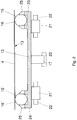
- FIG. 2 The sectional view of the support device 12 shown in FIG. 2 along the line II-II 'in FIG. 1 shows holding strips 23, 24 arranged on the two edges thereof for the rotatably mounted balls 16, 16'.
- the label 4 lies on its free surfaces 15, 15 'with its underside 13 coated with the pressure sensitive adhesive. Also indicated are bores 25, 25 'in the holding strips 23, 24 which serve to hold the balls 16, 16'. (As will be explained in more detail below)
- the arm 17, the projection 20, the two brackets 21, 21 'and the two nose-shaped projections 22, 22' are shown in plan view, which the attachment of the support device 12 to the printer housing 19 serve.
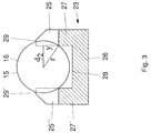
- the retaining strip 23 with a U-shaped cross section consists of a crossbar 26 with U-legs 27, 27 'on the edges thereof.
- the U-legs 27, 27' have mutually opposite bores 25, 25 '', the position of which in the U-legs 27 is illustrated in Fig. 4.
- the diameter of the bores 25, 25 ', 25'' is smaller than the diameter of the balls 16.
- the distance between the inner surface 28 of the cross piece 26 and the end faces 29, 29' the U-leg 27, 27 'be smaller than the distance between the inner surface 28 of the crossbar 26 and at least a portion 15 of the surface of the ball 16 facing away from the crossbar 26.
- the support table 12 is made of polyoxymethylene, which has the advantage that the support table 12 can be manufactured by injection molding.
- the balls 16 are made of polytetrafluoroethylene, which has the properties of exerting a minimal adhesive effect with respect to pressure-sensitive adhesives and, moreover, snapped between the U-legs 27, 27 'of the holding strip 23 so as to be easily rotatable, since there are between the materials from which the support table and the balls exist, there is minimal frictional resistance.
- Another advantage of polyoxymethylene is used in the manufacture of the holding strips 23, 24, namely to be particularly elastic. This makes it possible to press the balls 16 during assembly in the area of the bores 25, 25 ', 25' 'from above between the elastic side walls 27, 27' of the retaining strip 23 until they are in the bores 25, 25 ', 25 '' snap in.
Landscapes
- Labeling Devices (AREA)
Applications Claiming Priority (2)
| Application Number | Priority Date | Filing Date | Title |
|---|---|---|---|
| DE4313013 | 1993-04-21 | ||
| DE4313013A DE4313013A1 (de) | 1993-04-21 | 1993-04-21 | Vorrichtung zum Bedrucken von Etiketten |
Publications (2)
| Publication Number | Publication Date |
|---|---|
| EP0621137A2 true EP0621137A2 (fr) | 1994-10-26 |
| EP0621137A3 EP0621137A3 (fr) | 1995-03-08 |
Family
ID=6486005
Family Applications (1)
| Application Number | Title | Priority Date | Filing Date |
|---|---|---|---|
| EP94104766A Withdrawn EP0621137A3 (fr) | 1993-04-21 | 1994-03-25 | Dispositif d'impression d'étiquettes. |
Country Status (3)
| Country | Link |
|---|---|
| US (1) | US5395174A (fr) |
| EP (1) | EP0621137A3 (fr) |
| DE (1) | DE4313013A1 (fr) |
Cited By (1)
| Publication number | Priority date | Publication date | Assignee | Title |
|---|---|---|---|---|
| DE19513140A1 (de) * | 1995-04-07 | 1996-10-10 | Esselte Meto Int Gmbh | Vorrichtung zum Ausgeben von mit einer selbstklebenden Oberfläche versehenen Etiketten |
Families Citing this family (13)
| Publication number | Priority date | Publication date | Assignee | Title |
|---|---|---|---|---|
| WO1996040526A1 (fr) * | 1995-06-07 | 1996-12-19 | Moore Business Forms, Inc. | Procede d'impression sur des etiquettes a transfert thermique sans support pelliculaire comportant un agent silicone anti-adhesif |
| WO1999025554A2 (fr) * | 1997-10-31 | 1999-05-27 | Zebra Technologies Corporation | Imprimante |
| US6630998B1 (en) | 1998-08-13 | 2003-10-07 | Acushnet Company | Apparatus and method for automated game ball inspection |
| US6349756B1 (en) | 1998-10-23 | 2002-02-26 | Zih Corporation | Peel assembly for a printer |
| US6462812B1 (en) * | 2000-11-21 | 2002-10-08 | Callaway Golf Company | Golf ball indicia verification system |
| DE10124322A1 (de) * | 2001-05-17 | 2002-11-28 | Espera Werke Gmbh | Etikettendrucker |
| DE10337402A1 (de) * | 2003-08-13 | 2005-03-17 | Ingrid Judisch | Verfahren und Vorrichtung zum Etikettieren eines Produkts |
| US8374887B1 (en) | 2005-02-11 | 2013-02-12 | Emily H. Alexander | System and method for remotely supervising and verifying pharmacy functions |
| CN100515663C (zh) * | 2006-03-10 | 2009-07-22 | 鸿富锦精密工业(深圳)有限公司 | 成型方法及夹具 |
| BR112012008841A2 (pt) | 2009-10-13 | 2019-09-24 | Brady Worldwide Inc | mecanismo de destacamento e apresentação, aparelho para etiquetagem, metodo e aparelho para destacar etiquetas a partir de carga de etiqueta e apresentar as etiquetas destacadas ao longo de um de finido trajeto projetado, método de etiquetagem de uma superfície curva, e, método para dispensar uma etiqueta. |
| US9930297B2 (en) | 2010-04-30 | 2018-03-27 | Becton, Dickinson And Company | System and method for acquiring images of medication preparations |
| CA3180239A1 (fr) | 2014-09-08 | 2016-03-17 | Becton, Dickinson And Company | Plateau ameliore pour malaxage pharmaceutique |
| CN105083669B (zh) * | 2015-05-28 | 2018-01-12 | 青岛海信移动通信技术股份有限公司 | 一种标签打印机 |
Family Cites Families (23)
| Publication number | Priority date | Publication date | Assignee | Title |
|---|---|---|---|---|
| US2931477A (en) * | 1957-03-05 | 1960-04-05 | Metzgar Conveyor Co | Ball and plastic housing assembly |
| DE1189507B (de) * | 1962-04-06 | 1965-03-25 | Huettenwerk Oberhausen Ag | Materialtransportanlage fuer den UEbergang von der soehligen zur seigeren Foerderungoder umgekehrt in untertaegigen Bergwerksbetrieben |
| DE1761707A1 (de) * | 1968-06-27 | 1971-08-05 | Lothar Sump | Vorschub-Transportvorrichtung fuer ein Etikettentraegerband und/oder Etiketten bzw.Streifen an Etikettier- und Etikettendruckmaschinen |
| DE1786222A1 (de) * | 1968-09-03 | 1972-01-27 | Meto Gmbh Kind Oscar | Geraet zum Anbringen von selbstklebenden Etiketten,insbesondere an Gegenstaenden mit gewoelbter Oberflaeche |
| DE1927163C2 (de) * | 1969-05-28 | 1975-12-11 | Schaefer-Etiketten Heinrich Hubert Schaefer, 7441 Wolfschlugen | Etikettiergerät |
| US3664222A (en) * | 1970-04-07 | 1972-05-23 | Domain Ind Inc | Labeling machine |
| DE2126362C3 (de) * | 1971-05-27 | 1975-07-24 | Meto Ges Oscar Kind Gmbh | Gerät zum Bedrucken und bzw. oder Ausgeben von selbsthaftenden Etiketten |
| BE788033A (fr) * | 1971-08-25 | 1973-02-26 | Norprint Ltd | Perfectionnements relatifs aux dispositifs d'etiquetage |
| GB1428377A (en) * | 1972-06-30 | 1976-03-17 | Norprint Ltd | Labelling devices incorporating pressure-applying members |
| US3984279A (en) * | 1975-02-24 | 1976-10-05 | Rca Corporation | Labeling apparatus |
| US3989575A (en) * | 1975-04-16 | 1976-11-02 | Oliver Machinery Company | Split labeling apparatus |
| US4120245A (en) * | 1977-01-10 | 1978-10-17 | Sanitary Scale Company | Label printer |
| FR2384576A1 (fr) * | 1977-03-21 | 1978-10-20 | Eurotungstene | Outil de coupe en alliage dur revetu de carbonitrure de titane |
| FR2420492A1 (fr) * | 1978-03-22 | 1979-10-19 | Faber Guy | Dispositif de support pour organe porteur mobile, notamment pour bande de convoiement |
| JPS609031Y2 (ja) * | 1978-06-26 | 1985-04-01 | 株式会社サト−研究所 | ハンドラベラ−用の印字装置 |
| US4261788A (en) * | 1979-06-07 | 1981-04-14 | Mcclung Jack P | Roller and label applicator incorporating the same |
| JPS57183941A (en) * | 1981-04-30 | 1982-11-12 | Sato Co Ltd | Portable labeller |
| DE3207053A1 (de) * | 1982-02-26 | 1983-09-15 | Esselte Pendaflex Corp., 11530 Garden City, N.Y. | Etikettiergeraet |
| US4432830A (en) * | 1983-02-07 | 1984-02-21 | Intermec Corporation | Label printer having selectable label stock paths |
| US4473426A (en) * | 1983-04-12 | 1984-09-25 | Monarch Marking Systems, Inc. | Labeler |
| JPS61248760A (ja) * | 1985-04-26 | 1986-11-06 | Sato :Kk | サ−マルプリンタ |
| DE3823607A1 (de) * | 1987-07-13 | 1989-01-26 | Canon Kk | Blattbehandlungsvorrichtung und hiermit ausgestattetes bildaufzeichnungsgeraet |
| IT1239110B (it) * | 1990-03-06 | 1993-09-21 | Alfa Costr Mecc Spa | Perfezionamento in macchina etichettatrice per etichette autoadesive. |
-
1993
- 1993-04-21 DE DE4313013A patent/DE4313013A1/de not_active Withdrawn
-
1994
- 1994-03-25 EP EP94104766A patent/EP0621137A3/fr not_active Withdrawn
- 1994-04-19 US US08/229,518 patent/US5395174A/en not_active Expired - Fee Related
Cited By (1)
| Publication number | Priority date | Publication date | Assignee | Title |
|---|---|---|---|---|
| DE19513140A1 (de) * | 1995-04-07 | 1996-10-10 | Esselte Meto Int Gmbh | Vorrichtung zum Ausgeben von mit einer selbstklebenden Oberfläche versehenen Etiketten |
Also Published As
| Publication number | Publication date |
|---|---|
| DE4313013A1 (de) | 1994-10-27 |
| EP0621137A3 (fr) | 1995-03-08 |
| US5395174A (en) | 1995-03-07 |
Similar Documents
| Publication | Publication Date | Title |
|---|---|---|
| EP0621137A2 (fr) | Dispositif d'impression d'étiquettes | |
| DE2530346C3 (de) | Gerät zum Bedrucken und Ausgeben von Etiketten | |
| EP0883549B1 (fr) | Appareil d'etiquetage | |
| AT389684B (de) | Handetikettiergeraet | |
| DE3610075C2 (fr) | ||
| DE2265539C2 (de) | Vorrichtung zum Bedrucken, Ausgeben und Anbringen von Selbstklebeetiketten | |
| DE3150589A1 (de) | Schreibvorrichtung | |
| DE68919810T2 (de) | Nachtränk- und Transferrollen-Anordnung. | |
| DE3037324C2 (de) | Etikettiergerät | |
| AT1240U1 (de) | Handstempel, stempelplatte hiefür und stempelplattengarnitur | |
| EP0326568B1 (fr) | Tete d'ecriture a l'encre a couches multiples | |
| EP0723874A1 (fr) | Dispositif de timbre à encrage automatique | |
| DE1944857A1 (de) | Geraet zum Bedrucken oder Ausgeben von selbsthaftenden Etiketten | |
| EP0040287A1 (fr) | Dispositif de dosage de l'encre dans un encrier pour machines à imprimer offset ou presses typographiques | |
| DE69719266T2 (de) | Ölzerstäuber für Druckluft | |
| DE102021126287B3 (de) | Applikator zum Verkleben von zwei Fügeteilen mittels eines doppelseitig selbstklebenden Klebestreifens mit Anzeige ausreichender Anpresskraft | |
| DE2512471C3 (fr) | ||
| DE4408462A1 (de) | Druckwerk | |
| DE2635006A1 (de) | Vorrichtung zur automatischen abstandsregelung zwischen einem druckkopf und einem zu bedruckenden informationstraeger | |
| DE3026557A1 (de) | Fuellstandsregeleinrichtung an beleimungsvorrichtungen fuer blockruecken u.dgl. | |
| DE69718943T2 (de) | Vorrichtung für die kontrollierte diffusion von aktiven stoffen in pflanzenzucht und schutz vor parasiten in der landwirtschaft | |
| WO2004094255A1 (fr) | Dispositif d'application conçu en particulier pour une substance adhesive liquide ou visqueuse | |
| DE112017004389T5 (de) | Flüssigkeits-Appliziereinheit sowie Flüssigkeits-Appliziervorrichtung | |
| DE20311531U1 (de) | Montagehilfe | |
| AT379U1 (de) | Datumseinsatz fuer stempel |
Legal Events
| Date | Code | Title | Description |
|---|---|---|---|
| PUAI | Public reference made under article 153(3) epc to a published international application that has entered the european phase |
Free format text: ORIGINAL CODE: 0009012 |
|
| AK | Designated contracting states |
Kind code of ref document: A2 Designated state(s): AT DE DK ES FR GB IT NL |
|
| PUAL | Search report despatched |
Free format text: ORIGINAL CODE: 0009013 |
|
| AK | Designated contracting states |
Kind code of ref document: A3 Designated state(s): AT DE DK ES FR GB IT NL |
|
| 17P | Request for examination filed |
Effective date: 19950404 |
|
| GRAG | Despatch of communication of intention to grant |
Free format text: ORIGINAL CODE: EPIDOS AGRA |
|
| 17Q | First examination report despatched |
Effective date: 19960701 |
|
| STAA | Information on the status of an ep patent application or granted ep patent |
Free format text: STATUS: THE APPLICATION HAS BEEN WITHDRAWN |
|
| 18W | Application withdrawn |
Withdrawal date: 19961212 |