EP0621192B1 - Zusammenklappbare Schachtel und Zuschnitt - Google Patents
Zusammenklappbare Schachtel und Zuschnitt Download PDFInfo
- Publication number
- EP0621192B1 EP0621192B1 EP19940201102 EP94201102A EP0621192B1 EP 0621192 B1 EP0621192 B1 EP 0621192B1 EP 19940201102 EP19940201102 EP 19940201102 EP 94201102 A EP94201102 A EP 94201102A EP 0621192 B1 EP0621192 B1 EP 0621192B1
- Authority
- EP
- European Patent Office
- Prior art keywords
- flap
- side wall
- folding line
- lengthening
- pair
- Prior art date
- Legal status (The legal status is an assumption and is not a legal conclusion. Google has not performed a legal analysis and makes no representation as to the accuracy of the status listed.)
- Expired - Lifetime
Links
- 238000004519 manufacturing process Methods 0.000 claims description 12
- 230000001154 acute effect Effects 0.000 claims description 5
- 239000003292 glue Substances 0.000 description 3
- 239000000463 material Substances 0.000 description 3
- 238000010276 construction Methods 0.000 description 2
- 230000000694 effects Effects 0.000 description 2
- 230000000712 assembly Effects 0.000 description 1
- 238000000429 assembly Methods 0.000 description 1
- 230000002349 favourable effect Effects 0.000 description 1
Images


Classifications
-
- B—PERFORMING OPERATIONS; TRANSPORTING
- B65—CONVEYING; PACKING; STORING; HANDLING THIN OR FILAMENTARY MATERIAL
- B65D—CONTAINERS FOR STORAGE OR TRANSPORT OF ARTICLES OR MATERIALS, e.g. BAGS, BARRELS, BOTTLES, BOXES, CANS, CARTONS, CRATES, DRUMS, JARS, TANKS, HOPPERS, FORWARDING CONTAINERS; ACCESSORIES, CLOSURES, OR FITTINGS THEREFOR; PACKAGING ELEMENTS; PACKAGES
- B65D5/00—Rigid or semi-rigid containers of polygonal cross-section, e.g. boxes, cartons or trays, formed by folding or erecting one or more blanks made of paper
- B65D5/001—Rigid or semi-rigid containers of polygonal cross-section, e.g. boxes, cartons or trays, formed by folding or erecting one or more blanks made of paper stackable
- B65D5/0015—Rigid or semi-rigid containers of polygonal cross-section, e.g. boxes, cartons or trays, formed by folding or erecting one or more blanks made of paper stackable the container being formed by folding up portions connected to a central panel
- B65D5/0045—Rigid or semi-rigid containers of polygonal cross-section, e.g. boxes, cartons or trays, formed by folding or erecting one or more blanks made of paper stackable the container being formed by folding up portions connected to a central panel having both integral corner posts and ledges
Definitions
- the present invention relates to a collapsible box-shaped container provided with a bottom and two pairs of opposed upright side walls which are folded approximately square to the bottom, wherein the two opposed side walls of a first pair are each at both ends provided with a lengthening flap which is folded approximately square to the side wall, said lengthening flap being fastened with a part of its outer surface to a corresponding part of the inner surface of an adjacent side wall of the other pair, and wherein in said adjacent side wall each time from both bottom corner points a first diagonal folding line is provided extending upwardly at an acute angle, in such a way, that the portion of said other side wall which is fastened on the lengthening flap, is situated at the side of the first diagonal folding line turned a way from the bottom.
- Such a collapsible box-shaped container is known from EP-A-0 394 549.
- a first pair of upright side walls is provided with four flaps which form a rectangular tubular support which is to be unfolded and collapsed.
- the invention aims at the realization of an alternative to this known collapsible box-shaped container.
- each lengthening flap is provided with a connection flap which is double-folded on the lengthening flap and has substantially the same length as the lengthening flap, and with a fastening flap which is folded at an angle of approximately 90° with respect to the lengthening flap and is glued onto the side wall of the first pair provided with the lengthening flap.
- the present invention provides a container comprising a connection flap which is double-folded on the lengthening flap and a fastening flap which is glued to the side wall.
- the third flap from a side wall of the first pair cannot be glued to another part of the container since the rectangular tubular support has to be unfoldable and collapsible.
- each lengthening flap and connection flap adjacent to the folding line therebetween have been widened over a portion of the length of the flaps in the direction of the bottom, in such a way, that a double slip lip is formed, the height of the double slip lip being greater than the distance between the bottom edge of the lengthening flap and connection flap, respectively, and the folding line between the bottom and the side wall of the other pair.
- the double slip lip pushes with some force onto the bottom of the box when unfolding the box and when it is erected, as a result of which the side walls of the other pair, and therewith also the side walls of the one pair can be kept with certainty in a position perpendicular to the bottom, and thereby moreover friction forces become active between the underside of the double slip lip and the upper surface of the bottom, which prevent the double slip lip from slipping away inwardly over the bottom of the box.
- each lengthening flap adjacent to the folding line between lengthening flap and connection flap is heightened over a portion of the length of the lengthening flap in the direction of the bottom, in such a way, that a single slip lip is formed, wherein the folding line between lengthening flap and connection flap over a portion of the height of the flaps is replaced by a cut, and wherein the height of the single slip lip is greater than the distance between the bottom edge of the lengthening flap and the folding line between the bottom and side wall of the other pair.
- said lip is bent with a relatively great radius of curvature when unfolding the box, so that a relatively great force is exercised on the bottom of the box and thereby the resistance of the side walls of the box against folding inwardly is increased considerably with respect to the resistance of the known box.
- the greater length of the present slip lip compared to that of the slip lip of the known box further the danger for buckling of the slip lip is much smaller.
- the present invention also relates to a one-piece blank for manufacturing a box-shaped container according to the invention, comprising a bottom panel and four side wall panels which are foldably connected with the bottom panel, wherein of the one pair of opposed side wall panels each panel is provided with two opposed lengthening flaps which are foldably connected with the side wall panel, and wherein in the other pair of opposed side wall panels each time from the corner points of the bottom panel a substantially diagonal folding line is provided, each lengthening flap being provided with a connection flap, with a first folding line between lengthening flap and connection flap, said flaps having substantially the same length and that a fastening flap is connected to the connection flap, which fastening flap is connected to said connection flap by a second folding line, characterized in that each lengthening flap and each connection flap adjacent to the folding line therebetween are widened over a portion of the length of the flaps at the side of a side wall panel of the other pair, in such a way, that an extending double slip lip is formed and the said folding line extends through the
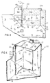
- Fig.1 illustrates a corner portion of a blank P1 according to the invention for manufacturing a collapsible box-shaped container, hereinafter simply called box, according to the invention, a corner portion of which being drawn in fig.2.
- the blank P1 consists of one piece and comprises a bottom panel 2 and two pairs of side wall panels 3 and 4 respectively, which are foldably connected with the bottom panel 2 along folding lines 5 and 6 respectively.
- the one pair of side wall panels 3 is each provided with two opposed lengthening flaps 7 which are connected with the side wall panel 3 along a folding line 8.
- a substantially diagonal folding line 9 is provided, the function of which is yet to be described.
- each lengthening flap 7 is provided with a connection flap 10 with a first folding line 11 between lengthening flap and connection flap.
- the lengthening flap 7 and the connection flap 10 have substantially the same length L1.
- Each connection flap 10 is provided with a fastening flap 12 connected to the connection flap by a second folding line 13.
- each lengthening flap 7 has a surface 7a (interrupted shading) at its side turned away from the reader, to which surface glue is applied for manufacturing the box D1
- each fastening flap 12 has a glued surface 12a (uninterrupted shading) at its side turned towards the reader.
- each lengthening flap 7 is glued with the surface 7a to a portion 4a of each side wall panel 4, and each fastening flap is glued with the surface 12a to the side wall panel 3, in such a way, that the folding lines 8 and 13 practically coincide.
- the box D1 is now in the form as is drawn in fig.2.
- the side walls 4, 4a adjacent the folding lines 9 are folded inwardly, and the side walls 4 are folded inwardly about the folding lines 6 over an angle of ⁇ 90° to the bottom, during which folding movement the side wall portions 4a and the lengthening flaps 7 and connection flaps 10 forming a whole therewith, are folded about the folding line 9 approximately flat to the side walls 4 and about the folding lines 13 approximately flat to the side walls 3, the latter in their turn are folded inwardly about the folding lines 5 over ⁇ 90° towards the bottom 2.
- Fig.3 illustrates a corner portion of a blank P2 for manufacturing a collapsible box D2 according to the invention, a corner portion of which is drawn in fig.4.
- the blank P2 consists of one piece and comprises a bottom panel 14, two pairs of side wall panels 15 and 16 respectively which are foldably connected with the bottom panel 14 along folding lines 17 and 18, respectively.
- the one pair of side wall panels 15 are each provided with two opposed lengthening flaps 19 which are connected with the side wall panels 15 along a folding line 20.
- each lengthening flap 19 is provided with a connection flap 21 with a first folding line 22 between lengthening flap and connection flap.
- the lengthening flaps 19 and connection flaps 21 substantially have the same length L2.
- Each connection flap 21 is provided with a fastening flap 23 which is connected to the connection flap by a second folding line 24.
- Each fastening flap 23 has also an extending lip 23b.
- each lengthening flap 19 has a surface 19a with interrupted shading at the side turned away from the reader, on which surface glue is applied for manufacturing the box D2, and each fastening flap 23 has a glued surface 23a with continuous shading at the side directed towards the reader.
- each side wall panel 15 of the one pair and in the bottom panel 14 a substantially rectangular recess 25 is provided adjacent to the folding line 17 and at a short distance of the bottom corner points B2. Further each side wall panel 15 of the one pair is provided with a widening strip 26 connected with the panel 15 by a folding line 27, each widening strip 26 adjacent to the folding line 27 and directly opposite the recess 25 in the side wall panel 15 being provided with a U-shaped cut 28 limiting a lip 29.
- the function of the lips 23b, recesses 25 and lips 29 will yet be explained further.
- each widening strip 26 from each end point V2 of the folding line 27 a second substantially diagonal folding line 30 is provided, while each widening strip 26 at both ends is provided with a retaining flap 31 connected with the widening strip 26 by a folding line 32.
- Each retaining flap 31 is provided with a glued surface 31a at the side turned away from the reader. The function of the widening strip 26 and retaining flap 31 will be discussed hereinafter.
- each side wall panel 16 of the other pair is provided with a first substantially diagonal folding line 33 from each bottom corner point B2.
- each lengthening flap 19 and each connection flap 21 adjacent the folding line 22 therebetween is widened over a portion of the length L2 of the flaps at the side of the side wall panel 16 of the other pair, in such a way, that an extending double slip lip 34 is formed and the folding line 22 extends through the slip lip 34, and the edge 35 of the side wall panel 16 opposite the double slip lip 34 is set back with respect to the imaginary extension 17a of the folding line 17 between the bottom panel 14 and the side wall panel 15 of the one pair, wherein the double slip lip 34 in the direction of the side wall panel 16 of the other pair extends beyond the imaginary extension 17a of the folding line 17.
- each retaining flap 31 When erecting the box D2 according to fig.4 each retaining flap 31 is glued with the surface 31a to the panel portion 16a, each lengthening flap 19 is glued with the surface 19a to the retaining flap 31 and to the panel portion 16a, and each fastening flap 23 is glued with the surface 23a to the side wall panel 15, in such a way, that the folding lines 20 and 24 substantially coincide.
- Each retaining flap 31 may also be glued between the lengthening flap 19 and the connection flap 21 or to the free surface of the connection flap 21 at the inside of the box D2.
- the squarely folded widening strips 26 at the side walls 15 of the one pair function as additional supporting means when stacking filled boxes D2.
- the double slip lips 34 press the bottom 14 as it were a bit downwards adjacent the slip lips and have the slip lips in this way a fixed position that warrants that the side walls of the box remain upright and perpendicularly to the bottom 14 of the box, also when the box D2 is filled.
- the great form stability of the erected box D2 also means that erecting the box from the folded down position, wherein first the side walls 16 of the other pair are folded on the bottom 14, and then the side walls 15 of the one pair are folded on the bottom, is somewhat more time-consuming than with the box D1 according to fig.2.
- the composed wall portions 16a, 19-21 with the slip lips 34 must still be pressed in the position perpendicular to the bottom 14, during which the "dragging" friction between the double slip lip 34 and the bottom 14 has to be overcome.
- this relatively insignificant disadvantage counts for little compared to the above-mentioned advantages of the box D2 with respect to the known box.
- Fig.5 illustrates a corner portion of a blank P3 for manufacturing a collapsible box D3 according to the invention, a corner portion of which being drawn in fig.6.
- the blank P3 also consists of one piece and comprises a bottom panel 37 and two pairs of side wall panels 38 and 39 which are foldably connected with the bottom panel 37 along folding lines 40 and 41.
- the one pair of side wall panels 38 are each provided with two opposed lengthening flaps 42 which are connected with the side wall panels 38 along a folding line 43.
- connection flap 44 to each lengthening flap 42 along a folding line 43a.
- the lengthening flaps 43 and connection flaps 44 have substantially the same length L3.
- Each connection flap 44 is provided with a fastening flap 46 along a second folding line 45.
- Each fastening flap 46 has yet an extending lip 46b.
- Each lengthening flap 42 has further a glued surface 42a at the side turned away from the reader, which surface is indicated with an interrupted shading and each fastening flap 46 has a glued surface 46a with a continuous shading at the side directed towards the reader.
- each side wall panel 38 of the one pair and in the bottom panel 37 a substantially rectangular recess 47 is made adjacent to the folding line 40 at a short distance from the bottom corner point B3. Furthermore, each side wall panel 38 of the one pair is provided with a widening strip 48 which is connected with the side wall panel 38 by a folding line 49, wherein in each widening strip 48 a U-shaped cut 50, limiting a lip 51, is made adjacent the folding line 49 and directly opposite the recess 47 in the side wall panel 38.
- the function of the lips 46b, the recesses 47 and the lips 51 will yet be further elucidated.
- each widening strip 48 at both ends is provided with a retaining flap 53 which is connected with the widening strip 48 by a folding line 54.
- Each retaining flap 53 is provided with a glued surface 53a at the side turned away from the reader. The function of the widening strips 48 and the retaining flaps 53 will be discussed hereinafter. Also with the blank P3 in each side wall panel 39 of the other pair from each bottom point B3 a first substantially diagonal folding line 55 is provided.
- each lengthening flap 42 adjacent the folding line 43a between lengthening flap and connection flap 44 is widened over a portion of the length L3 of the flaps at the side of the side wall panel 39 of the other pair, in such a way, that a single slip lip 56 is formed, wherein the folding line 43a between lengthening flap 42 and connection flap 44 is replaced by a cut 57 over a portion of the width of the flaps, wherein the width H of the single slip lip 55 is greater than the distance A3 between the inner edge 42b of the lengthening flap 42 and the imaginary extension 40a of the folding line 40 between bottom panel 37 and side wall 38 of the one pair, and wherein the edge 39b of the side wall panel 39 of the other pair with respect to the single slip lip 56 is set back with respect to the imaginary extension 40a of the folding line 40 between bottom panel 37 and side wall panel 38 of the one pair.
- each retaining flap 53 with the glued surface 53a is glued to the panel portion 39a
- each lengthening flap 42 with the glued surface 42a is glued to the retaining flap 53 and the panel portion 39a
- each fastening flap 46 with the glued surface 46a is glued to the side wall panel 38, in such a way, that the folding lines 43 and 43a substantially coincide.
- Each retaining flap 53 may also be glued to the free surface of the connection flap 44 between the lengthening flap 42 of the box D3.
- the cut 57 in the blank P3 is made such that the side edge 56a of the single slip lip 56 turned away from the adjacent bottom corner point B3, which side edge is formed by a cut, encloses an acute angle ⁇ with the folding line 41 between the bottom 37 and the side wall 39 of the other pair and opening towards the bottom corner point. This causes the single slip lip 51 to act in an optimal way, as will be seen hereinafter.
- the squarely folded widening strips 48 at the side walls 38 of the one pair function as additional supporting means when stacking filled boxes D3.
- the single slip lips 56 press the bottom 37 adjacent the slip lips as it were a bit downwardly, whereas the slip lips 56 themselves, seen from the inside of the box, are curved slightly concavely. In this way a relatively high frictional resistance has to be overcome to bring the box D3 from its position according to fig.6 in its substantially collapsed position (not drawn). Therefore the box D3 remains in the position according to fig.6 when once brought into said position, in particular during handling and transportation of the filled boxes.
- the box D3 according to fig.6 also obtains a relatively high strength, load bearing capacity and form stability with a relatively small material consumption, as has been further explained above on the basis of the figures 2 and 4.
- erecting the substantially collapsed box D3, wherein first the side walls 39 of the other pair are folded towards the bottom 37 over ⁇ 90° and then the side walls 38 of the one pair are folded towards the bottom 37 onto the side walls 39 over ⁇ 90° goes very easily and rapidly, because only the side walls 38 of the one pair need to be pulled upwardly from the bottom 37, until they are substantially perpendicular to the bottom 37, in order to erect the side walls 39 of the other pair in the position substantially perpendicular to the bottom 37 in one movement with the side walls 38 of the one pair by means of the tangantial folding line 55 and the assemblies of flaps 44, 42 and 53, which are glued to the side wall portion 39a, during which the single slip lips 56 slip over the bottom and adopt in one movement an inwardly directed somewhat concave shape in the position according to fig.6.
- slip lips 56 need not be pressed aditionally and manually towards the side walls 39, which makes the use of the box D3 easier.
- the slip lip 56 can be situated as far away as possible from the corner point B3, because the side edge 56a of the slip lip 56 encloses an acute angle ⁇ with the folding line 41, which increases the effect of the slip lip 56.
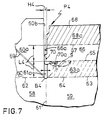
- fig. 7 illustrates a part of a corner portion of a blank P4 which is substantially equal to the blank P3.
- the blank P4 consisting of one piece comprises a bottom panel 58 and two pairs of side wall panels 59 and 60, 60a which are foldably connected with the bottom panel 58 along folding lines 61 and 62.
- the one pair of side wall panels 59 is each provided with two opposed lengthening flaps 63 which are connected with the side wall panels 59 along folding lines 64 and which have a glued surface 63a corresponding to the glued surface 42a of the blank P3.
- each lengthening flap 63 is provided with a connection flap 66 along a folding line 65, and in each side wall panel 60 of the other pair from each bottom corner point B4 is provided a first substantially diagonal folding line 69 having the same function as the diagonal folding lines 55, 33 and 9 of the blanks P3, P2 and P1 respectively.
- each connection flap 66 adjacent the folding line 65 between connection flap and lengthening flap 63 is widened over a portion of the length L4 of the flaps at the side of the side wall panel 60 of the other pair, in such a way, that a single slip lip 70 is formed, wherein the folding line 65 over a portion of the width of the flaps is replaced by a cut 71 and wherein the width H4 of the single slip lip 70 is greater than the distance A4 between the inner edge 66a of the connection flap 66 and the imaginary extension 61a of the folding line 61 between bottom panel 58 and side wall panel 59 of the other pair, and wherein the edge 60b of the side wall panel 60 of the other pair opposite the single slip lip 70 is set back with respect to the imaginary extension 61a of the folding line 61 between bottom panel 58 and side wall panel 59 of the one pair.
- the cut 71 is further made in the same manner as the cut in the blank P3.
- Erecting a box from the blank P4 according to fig.7 is done in the same manner as the box D3 from the blank P3.
- the single slip lips 70 of such a box show substantially the same behaviour, perform substantially the same functions and have substantially the same effect as the single slip lips 56 of the box D3 according to fig.6.
- the reinforced corner construction of the box D1 can be used with the boxes D2, D3 and D4, whereas reversely the single slip lip 65 or 70 or the double slip lip 34 of the box D3 or D4, and of the box D2 respectively, can also be used with the box D1. Further the reinforced corner construction and the single or double slip lip according to the invention can be used with each collapsible box-shaped container which falls within the scope of the enclosed claims.
Landscapes
- Engineering & Computer Science (AREA)
- Mechanical Engineering (AREA)
- Cartons (AREA)
Claims (9)
- Ein zusammemklappbarer, dosenförmiger Behälter (D1, D2, D3) mit einem Boden (2, 14, 37) und zwei Paar einanderentgegengesetzten, aufstehenden Seitenwänden (3, 4; 15, 16; 38, 39), die ungefähr rechtwinklig zum Boden (2, 14, 37) hin umgefaltet sind, wobei die zwei einander entgegengesetzten Seitenwände (3, 15, 38) eines ersten Paares jede an beiden Enden mit einer ungefähr rechtwinklig zur Seitenwand (3, 15, 38) hin umgefalteten Verlängerungsklappe (7, 19, 42), wobei die Verlängerungsklappe (7, 19, 42) mit einem Teil (7a, 19a, 42a) seiner Außenfläche an einem entsprechenden Teil der Innenfläche einer angrenzenden Seitenwand (4, 16, 39) eines anderen Paares befestigt ist und wobei in der angrenzenden Seitenwand (4, 16, 39) jeweils von beiden unteren Eckpunkte (B1, B2, B3) eine erste diagonale unter einem spitzen Winkel nach oben verlaufende Faltlinie (9, 33, 55) versehen ist, derart, daß der auf der Verlängerungsklappe ( 7, 19, 42) befestigten Abschnitt der anderen Seitenwand (4, 16, 39) sich an der Seite der vom Boden (2, 14, 37) abgewandten ersten diagonalen Faltlinie (9, 33, 55) befindet,
dadurch gekennzeichnet, daß jede Verlängerungsklappe (7, 19, 42) mit einer auf der Verlängerungsklappe (7, 19, 42) doppelt gefalteten Verbindungsklappe (10, 21, 44) versehen ist und im wesentlichen die gleiche Länge aufweist als die Verlängerungsklappe (7, 19, 42), und mit einer hinsichtlich der Verlängerungsklappe (7, 19, 42) unter einem Winkel von ungefähr 90° gefalteten Befestigungsklappe (12, 23, 46) und an der Seitenwand (3, 15, 38) des ersten Paares mit der Verlängerungsklappe (7, 19, 42) geklebt ist. - Ein dosenförmiger Behälter (D2) nach Anspruch 1, dadurch gekennzeichnet, daß jede Verlängerungsklappe (19) und die Verbindungsklappe (21) neben der Faltlinie (22) dazwischen über einen Abschnitt der Länge (L2) der Klappen in Richtung des Bodens (14) erweitert worden sind, derart, daß eine doppelte Schlepplippe (34) gebildet ist, wobei die Höhe (h) der doppelten Schlepplippe (34) größer ist als der Abstand (a) zwischen dem Unterrand (19b bzw. 21b) der Verlängerungsklappe (19) bzw. der Verbindungsklappe (21), und die Faltlinie (18) zwischen dem Boden (14) und der Seitenwand (16) des anderen Paares.
- Ein dosenförmiger Behälter (D3) nach Anspruch 1, dadurch gekennzeichnet, daß jede Verlängerungsklappe (42) neben der Faltlinie zwischen Verlängerungsklappe (42) und Verbindungsklappe (44) über einen Abschnitt der Länge der Verlängerungsklappe (42) in Richtung des Bodens (37) erhöht ist, derart, daß eine einzelne Schlepplippe (56) gebildet wird, wobei ein Abschnitt der Faltlinie zwischen Verlängerungsklappe (42) und Verbindungsklappe (44) durch einen Schnitt (57) ersetzt wird, und wobei die Höhe (H3) der einzelne Schlepplippe (56) größer ist als der Abstand (A3) zwischen Unterrand (42b) der Verlängerungsklappe und der Faltlinie (41) zwischen Boden (37) und Seitenwand des anderen Paares.
- Ein dosenförmiger Behälter nach Anspruch 1, dadurch gekennzeichnet, daß jede Verbindungsklappe (66) neben der Faltlinie zwischen Verlängerungsklappe (63) und Verbindungsklappe (66) über einen Abschnitt der Länge der Verbindungsklappe (66) in Richtung des Bodens (58) erhöht ist, derart, daß eine einzelne Schlepplippe (70) gebildet wird, wobei ein Abschnitt der Faltlinie zwischen Verlängerungsklappe (63) und Verbindungsklappe (66) durch einen Schnitt (71) ersetzt wird, und wobei die Höhe (H4) der einzelnen Schlepplippe (70) größer ist als der Abstand (A4) zwischen dem Unterrand (66a) der Verbindungsklappe (66) und der Faltlinie (62) zwischen dem Boden (58) und der Seitenwand (60) des anderen Paares.
- Ein dosenförmiger Behälter nach Anspruch 3 oder 4, dadurch gekennzeichnet, daß jeder Schnitt (57, 71) derart versehen (D3) ist, daß der vom Schnitt (57, 71) gebildeten Seitenrand (56a, 70a) der einzelnen vom angrenzenden unterem Eckenpunkt (B3, B4) abgewandeten Schlepplippe (56, 70) einen zum unteren Eckpunkt (B3, B4) hin offenen rechten Winkel (α) einschließt, mit der Faltlinie (41, 62) zwischen Boden (37, 58) und Seitenwand (39, 60) des anderen Paares.
- Ein einstückiger Planobogen (P2) zur Herstellung eines dosenförmigen Behälters nach Anspruch 2, mit einer Bodenplatte (14) und vier mit der Bodenplatte (14) faltbar verbundenen Seitenwandplatten (15, 16), wobei von dem einen Paar einander entgegengesetzten Seitenwandplatten (15) jede Platte mit zwei entgegengesetzten mit der Seitenwandplatte (15) in faltbarer Verbindung stehenden Verlängerungsklappen (19) versehen ist, und wobei im anderen Paar entgegengesetzten Seitenwandplatten (16) jeweils von den Eckpunkten (B2) der Bodenplatte (14) eine im wesentlichen diagonale Faltlinie (33) versehen ist, wobei jede Verlängerungsklappe (19) eine Verbindungsklappe (21) aufweist, mit einer ersten Faltlinie (22) zwischen Verlängerungsklappe (19) und Verbindungklappe (21), wobei die Klappen (19, 21) im wesentlichen die gleiche Länge (L2) haben und daß eine Befestigungsklappe (23) mit der Verbindungsklappe (21) verbunden ist, welche Befestigungsklappe (23) mit der Verbindungsklappe (21) mittels einer zweiten Faltlinie (24) verbunden ist, dadurch gekennzeichnet, daß jede Verlängerungsklappe (19) und jede Verbindungsklappe (21) neben der Faltlinie (22) dazwischen über einen Abschnitt der Länge der Klappen (19, 22) an der Seite einer Seitenwandplatte (16) des anderen Paares (16) erweitert sind, derart, daß eine vorspringende doppelte Schlepplippe (34) gebildet wird und die Faltlinie (22) sich durch die Schlepplippe (34) erstreckt und daß der Rand (35) der Seitenwandplatte (16) gegenüber der doppelten Schlepplippe (34) bezüglich des imaginären Vorsprungs (17a) der Faltlinie (17) zwischen der Bodenplatte (14) und der Seitenwandplatte (15) des einen Paares zurückversetzt ist, wobei sich die doppelte Schlepplippe (34) in Richtung der Seitenwandplatte (16) des anderen Paares vorbei des imaginären Vorsprungs (17a) der Faltlinie (17) erstreckt.
- Ein einstückiger Planobogen (P3) zur Herstellung eines dosenförmigen Behälters nach Anspruch 3, mit einer Bodenplatte (37) und vier mit der Bodenplatte (37) faltbar verbundenen Seitenwandplatten (38, 39), wobei von dem einen Paar (38) einander entgegengesetzten Seitenwandplatten jede Platte (38) mit zwei entgegengesetzten mit der Seitenwandplatte (38) in faltbarer Verbindung stehenden Verlängerungsklappen (42) versehen ist, und wobei im anderen Paar (39) entgegengesetzten Seitenwandplatten jeweils von den Eckpunkten (B3) der Bodenplatte (37) eine im wesentlichen diagonale Faltlinie (55) versehen ist, wobei jede Verlängerungsklappe (42) eine Verbindungsklappe (44) aufweist, mit einer ersten Faltlinie zwischen Verlängerungsklappe (42) und Verbindungklappe (44), wobei die Klappen (42, 44) im wesentlichen die gleiche Länge (L3) haben und daß eine Befestigungsklappe (46) mit der Verbindungsklappe (44) verbunden ist, welche Befestigungsklappe (46) mittels einer zweiten Faltlinie (45) mit der Verbindungsklappe (44) verbunden ist, dadurch gekennzeichnet, daß jede Verlängerungsklappe (42) neben der Faltlinie zwischen Verlängerungsklappe (42) und Verbindungsklappe (44) über einen Abschnitt der Länge (L3) der Verlängerungsklappe (42) in Richtung der Seitenwandplatte (39) des anderen Paares erweitert ist, derart, daß eine einzelne Schlepplippe (56) gebildet wird, wobei ein Abschnitt der Faltlinie zwischen Verlängerungsklappe (42) und Verbindungsklappe (44) durch einen Schnitt (57) ersetzt wird, wobei die Breite (H3) der einzelnen Schlepplippe (56) größer ist als der Abstand (A3) zwischen dem Innenrand der Verlängerungsklappe (42) und dem imaginären Vorsprung (40a) der Faltlinie (40) zwischen Bodenplatte (37) und Seitenwandplatte (38) des einen Paares, und wobei der Rand (39b) der Seitenwandplatte (39) des anderen Paares gegenüber der einzelnen Schlepplippe (56) bezüglich des Vorsprunges (40a) der Faltlinie (40) zwischen Bodenplatte (37) und Seitenwandplatte (38) des einen Paares zurückversetzt ist.
- Ein einstückiger Planobogen (P4) zur Herstellung eines dosenförmigen Behälters nach Anspruch 4, mit einer Bodenplatte (58) und vier mit der Bodenplatte (58) faltbar verbundenen Seitenwandplatten (59, 60), wobei von dem einen Paar (59) einander entgegengesetzten Seitenwandplatten jede Platte (59) mit zwei entgegengesetzten mit der Seitenwandplatte (59) in faltbarer Verbindung stehenden Verlängerungsklappen (63) versehen ist, und wobei im anderen Paar (60) entgegengesetzten Seitenwandplatten jeweils von den Eckpunkten (B4) der Bodenplatte (58) eine im wesentlichen diagonale Faltlinie (69) versehen ist, wobei jede Verlängerungsklappe (63) eine Verbindungsklappe (66) aufweist, mit einer ersten Faltlinie zwischen Verlängerungsklappe (63) und Verbindungklappe (66), wobei die Klappen (63, 66) im wesentlichen die gleiche Länge (L4) haben und daß eine Befestigungsklappe (68) mit der Verbindungsklappe (66) verbunden ist, welche Befestigungsklappe (68) mittels einer zweiten Faltlinie (67) mit der Verbindungsklappe (66) verbunden ist, dadurch gekennzeichnet, daß jede Verlängerungsklappe (66) neben der Faltlinie zwischen Verlängerungsklappe (63) und Verbindungsklappe (66) über einen Abschnitt der Länge (L4) der Verlängerungsklappe (66) in Richtung der Seitenwandplatte (60) des anderen Paares erweitert ist, derart, daß eine einzelne Schlepplippe (70) gebildet wird, wobei ein Abschnitt der Faltlinie zwischen Verlängerungsklappe (63) und Verbindungsklappe (66) durch einen Schnitt (71) ersetzt wird, wobei die Breite (H4) der einzelnen Schlepplippe (70) größer ist als der Abstand (A4) zwischen dem Innenrand (66a) der Verbindungsklappe (66) und dem imaginären Vorsprung (61a) der Faltlinie (61) zwischen Bodenplatte (58) und Seitenwandplatte (59) des einen Paares, und wobei der Rand (60b) der Seitenwandplatte (60) des anderen Paares gegenüber der Schlepplippe (70) bezüglich des imaginären Vorsprunges (61a) der Faltlinie (61) zwischen der Bodenplatte (58) und der Seitenwandplatte (59) des einen Paares zurückversetzt ist.
- Ein Planobogen (P3, P4) nach Anspruch 7 oder 8, dadurch gekennzeichnet, daß jeder Schnitt (57, 71) einen stumpfen Winkel (β) mit einer Faltlinie (43a, 65) zwischen Verlängerungsklappe (42, 63) und Verbindungsklappe (44, 66) einschließt.
Applications Claiming Priority (2)
| Application Number | Priority Date | Filing Date | Title |
|---|---|---|---|
| NL9300676 | 1993-04-21 | ||
| NL9300676A NL9300676A (nl) | 1993-04-21 | 1993-04-21 | Opvouwbare doosvormige houder en plano daarvoor. |
Publications (2)
| Publication Number | Publication Date |
|---|---|
| EP0621192A1 EP0621192A1 (de) | 1994-10-26 |
| EP0621192B1 true EP0621192B1 (de) | 1998-06-03 |
Family
ID=19862310
Family Applications (1)
| Application Number | Title | Priority Date | Filing Date |
|---|---|---|---|
| EP19940201102 Expired - Lifetime EP0621192B1 (de) | 1993-04-21 | 1994-04-21 | Zusammenklappbare Schachtel und Zuschnitt |
Country Status (3)
| Country | Link |
|---|---|
| EP (1) | EP0621192B1 (de) |
| DK (1) | DK0621192T3 (de) |
| NL (1) | NL9300676A (de) |
Cited By (1)
| Publication number | Priority date | Publication date | Assignee | Title |
|---|---|---|---|---|
| EP1764310A1 (de) | 2005-09-15 | 2007-03-21 | R&F Folding Boxes | Zusammenklappbare Schachtel und Zuschnitt |
Families Citing this family (6)
| Publication number | Priority date | Publication date | Assignee | Title |
|---|---|---|---|---|
| FR2728867B1 (fr) * | 1994-12-30 | 1997-03-21 | Sca Emballage France | Emballage en carton genre plateau ou barquette a coins de renforcement et son flan d'obtention |
| GR960100223A (el) | 1996-07-01 | 1998-03-31 | Οικονομικο χαρτοκιβωτιο. | |
| EP1764311B1 (de) * | 2005-09-15 | 2009-04-08 | VPK Packaging Group | Zusammenklappbare Schachtel und zugehöriger Zuschnitt |
| NL1034330C2 (nl) | 2007-09-04 | 2009-03-05 | Smurfit Kappa Gsf B V | Doos met hoekverstevigingen, daarvoor bestemde plano en werkwijze voor het opzetten daarvan. |
| DE202012010231U1 (de) * | 2012-10-26 | 2013-10-28 | Baypack Gmbh | Transportsteige, insbesondere für Gemüse oder Obst |
| CN114834724B (zh) * | 2022-06-01 | 2024-05-14 | 常州市万弘包装有限公司 | 一种省材型组装式包装盒 |
Family Cites Families (4)
| Publication number | Priority date | Publication date | Assignee | Title |
|---|---|---|---|---|
| DE1192974B (de) * | 1961-01-07 | 1965-05-13 | Friedrich Freund O H G | Faltsteige fuer Obst, Gemuese od. dgl. |
| US4056223A (en) * | 1976-08-11 | 1977-11-01 | Packaging Corporation Of America | Foldable container and blank therefor |
| DE3913890A1 (de) * | 1989-04-27 | 1990-10-31 | Hoffmann Guenter Gmbh Co Kg | Obst- oder gemuesekiste |
| NL193826C (nl) * | 1990-11-05 | 2000-12-04 | Smurfit Solidpack B V | Stapelbare kartonnen doos met hoekverstevigingen. |
-
1993
- 1993-04-21 NL NL9300676A patent/NL9300676A/nl not_active Application Discontinuation
-
1994
- 1994-04-21 EP EP19940201102 patent/EP0621192B1/de not_active Expired - Lifetime
- 1994-04-21 DK DK94201102T patent/DK0621192T3/da active
Cited By (1)
| Publication number | Priority date | Publication date | Assignee | Title |
|---|---|---|---|---|
| EP1764310A1 (de) | 2005-09-15 | 2007-03-21 | R&F Folding Boxes | Zusammenklappbare Schachtel und Zuschnitt |
Also Published As
| Publication number | Publication date |
|---|---|
| NL9300676A (nl) | 1994-11-16 |
| DK0621192T3 (da) | 1999-03-22 |
| EP0621192A1 (de) | 1994-10-26 |
Similar Documents
| Publication | Publication Date | Title |
|---|---|---|
| US5588585A (en) | Automatic set-up carton with corner posts | |
| US6386437B1 (en) | Container with automatically closing bottom structure | |
| US6098873A (en) | One piece folded and glued container with tabbed columns | |
| US4760922A (en) | Combination pallet and collapsible container mounted thereon | |
| US4410129A (en) | Collapsible paperboard container | |
| US20020074388A1 (en) | Container having improved stacking strength | |
| AU6906198A (en) | Broadsheet from cardboard for constructing a stackable box and thus obtained box | |
| US5104035A (en) | Carton with hinge lock construction | |
| EP1084957A1 (de) | Stabelbarer Behälter aus Karton und Zuschnitt | |
| US6290123B1 (en) | Bottom structure for collapsible container | |
| US4403728A (en) | Collapsible gable top container | |
| US4864940A (en) | Collapsible pallet | |
| US7607567B2 (en) | One-piece shipping container with differently contoured inner and outer walls and a quick-lock bottom | |
| US5573175A (en) | Octagonal container with lock bottom | |
| US5014905A (en) | Tapered carton and blank for forming it | |
| EP0621192B1 (de) | Zusammenklappbare Schachtel und Zuschnitt | |
| GB2137170A (en) | A Box or Tray made from a Folded Blank | |
| US4899927A (en) | Collapsible container | |
| US5749513A (en) | Corrugated paperboard box with reinforced side walls | |
| US5775571A (en) | Automatic pop up, bulk bin, multi-sided container apparatus | |
| US4027818A (en) | Self locking container | |
| US4235158A (en) | Method of making high strength shipping carton | |
| EP1215125A1 (de) | Faltschachtel mit Eckverstärkung und Zuschnitt dafür | |
| EP0393253B1 (de) | Faltschachtel und Zuschnitt dafür | |
| US6105855A (en) | Self locking paperboard lid |
Legal Events
| Date | Code | Title | Description |
|---|---|---|---|
| PUAI | Public reference made under article 153(3) epc to a published international application that has entered the european phase |
Free format text: ORIGINAL CODE: 0009012 |
|
| AK | Designated contracting states |
Kind code of ref document: A1 Designated state(s): BE DK ES FR GB NL |
|
| 17P | Request for examination filed |
Effective date: 19950222 |
|
| 17Q | First examination report despatched |
Effective date: 19960313 |
|
| GRAG | Despatch of communication of intention to grant |
Free format text: ORIGINAL CODE: EPIDOS AGRA |
|
| GRAG | Despatch of communication of intention to grant |
Free format text: ORIGINAL CODE: EPIDOS AGRA |
|
| GRAH | Despatch of communication of intention to grant a patent |
Free format text: ORIGINAL CODE: EPIDOS IGRA |
|
| GRAH | Despatch of communication of intention to grant a patent |
Free format text: ORIGINAL CODE: EPIDOS IGRA |
|
| GRAA | (expected) grant |
Free format text: ORIGINAL CODE: 0009210 |
|
| AK | Designated contracting states |
Kind code of ref document: B1 Designated state(s): BE DK ES FR GB NL |
|
| PG25 | Lapsed in a contracting state [announced via postgrant information from national office to epo] |
Ref country code: ES Free format text: THE PATENT HAS BEEN ANNULLED BY A DECISION OF A NATIONAL AUTHORITY Effective date: 19980603 |
|
| ET | Fr: translation filed | ||
| REG | Reference to a national code |
Ref country code: DK Ref legal event code: T3 |
|
| PLBE | No opposition filed within time limit |
Free format text: ORIGINAL CODE: 0009261 |
|
| STAA | Information on the status of an ep patent application or granted ep patent |
Free format text: STATUS: NO OPPOSITION FILED WITHIN TIME LIMIT |
|
| 26N | No opposition filed | ||
| REG | Reference to a national code |
Ref country code: GB Ref legal event code: IF02 |
|
| PGFP | Annual fee paid to national office [announced via postgrant information from national office to epo] |
Ref country code: FR Payment date: 20110418 Year of fee payment: 18 |
|
| PGFP | Annual fee paid to national office [announced via postgrant information from national office to epo] |
Ref country code: NL Payment date: 20110502 Year of fee payment: 18 Ref country code: DK Payment date: 20110420 Year of fee payment: 18 Ref country code: GB Payment date: 20110420 Year of fee payment: 18 Ref country code: BE Payment date: 20110404 Year of fee payment: 18 |
|
| BERE | Be: lapsed |
Owner name: *GSF VERPAKKINGEN B.V. Effective date: 20120430 |
|
| REG | Reference to a national code |
Ref country code: NL Ref legal event code: V1 Effective date: 20121101 |
|
| REG | Reference to a national code |
Ref country code: DK Ref legal event code: EBP |
|
| GBPC | Gb: european patent ceased through non-payment of renewal fee |
Effective date: 20120421 |
|
| REG | Reference to a national code |
Ref country code: FR Ref legal event code: ST Effective date: 20121228 |
|
| PG25 | Lapsed in a contracting state [announced via postgrant information from national office to epo] |
Ref country code: BE Free format text: LAPSE BECAUSE OF NON-PAYMENT OF DUE FEES Effective date: 20120430 Ref country code: GB Free format text: LAPSE BECAUSE OF NON-PAYMENT OF DUE FEES Effective date: 20120421 |
|
| PG25 | Lapsed in a contracting state [announced via postgrant information from national office to epo] |
Ref country code: FR Free format text: LAPSE BECAUSE OF NON-PAYMENT OF DUE FEES Effective date: 20120430 |
|
| PG25 | Lapsed in a contracting state [announced via postgrant information from national office to epo] |
Ref country code: NL Free format text: LAPSE BECAUSE OF NON-PAYMENT OF DUE FEES Effective date: 20121101 |
|
| PG25 | Lapsed in a contracting state [announced via postgrant information from national office to epo] |
Ref country code: DK Free format text: LAPSE BECAUSE OF NON-PAYMENT OF DUE FEES Effective date: 20120430 |