EP0621412B1 - Accouplement permanent entre deux arbres - Google Patents
Accouplement permanent entre deux arbres Download PDFInfo
- Publication number
- EP0621412B1 EP0621412B1 EP94105745A EP94105745A EP0621412B1 EP 0621412 B1 EP0621412 B1 EP 0621412B1 EP 94105745 A EP94105745 A EP 94105745A EP 94105745 A EP94105745 A EP 94105745A EP 0621412 B1 EP0621412 B1 EP 0621412B1
- Authority
- EP
- European Patent Office
- Prior art keywords
- drive shaft
- coupling
- shaft
- sleeve
- cup
- Prior art date
- Legal status (The legal status is an assumption and is not a legal conclusion. Google has not performed a legal analysis and makes no representation as to the accuracy of the status listed.)
- Expired - Lifetime
Links
- 230000008878 coupling Effects 0.000 title claims description 25
- 238000010168 coupling process Methods 0.000 title claims description 25
- 238000005859 coupling reaction Methods 0.000 title claims description 25
- 241000209035 Ilex Species 0.000 description 2
- 230000005540 biological transmission Effects 0.000 description 2
- 230000006978 adaptation Effects 0.000 description 1
Images
Classifications
-
- F—MECHANICAL ENGINEERING; LIGHTING; HEATING; WEAPONS; BLASTING
- F16—ENGINEERING ELEMENTS AND UNITS; GENERAL MEASURES FOR PRODUCING AND MAINTAINING EFFECTIVE FUNCTIONING OF MACHINES OR INSTALLATIONS; THERMAL INSULATION IN GENERAL
- F16H—GEARING
- F16H57/00—General details of gearing
- F16H57/0018—Shaft assemblies for gearings
- F16H57/0025—Shaft assemblies for gearings with gearing elements rigidly connected to a shaft, e.g. securing gears or pulleys by specially adapted splines, keys or methods
-
- F—MECHANICAL ENGINEERING; LIGHTING; HEATING; WEAPONS; BLASTING
- F16—ENGINEERING ELEMENTS AND UNITS; GENERAL MEASURES FOR PRODUCING AND MAINTAINING EFFECTIVE FUNCTIONING OF MACHINES OR INSTALLATIONS; THERMAL INSULATION IN GENERAL
- F16D—COUPLINGS FOR TRANSMITTING ROTATION; CLUTCHES; BRAKES
- F16D1/00—Couplings for rigidly connecting two coaxial shafts or other movable machine elements
- F16D1/06—Couplings for rigidly connecting two coaxial shafts or other movable machine elements for attachment of a member on a shaft or on a shaft-end
- F16D1/08—Couplings for rigidly connecting two coaxial shafts or other movable machine elements for attachment of a member on a shaft or on a shaft-end with clamping hub; with hub and longitudinal key
- F16D1/09—Couplings for rigidly connecting two coaxial shafts or other movable machine elements for attachment of a member on a shaft or on a shaft-end with clamping hub; with hub and longitudinal key with radial clamping due to axial loading of at least one pair of conical surfaces
-
- F—MECHANICAL ENGINEERING; LIGHTING; HEATING; WEAPONS; BLASTING
- F16—ENGINEERING ELEMENTS AND UNITS; GENERAL MEASURES FOR PRODUCING AND MAINTAINING EFFECTIVE FUNCTIONING OF MACHINES OR INSTALLATIONS; THERMAL INSULATION IN GENERAL
- F16D—COUPLINGS FOR TRANSMITTING ROTATION; CLUTCHES; BRAKES
- F16D1/00—Couplings for rigidly connecting two coaxial shafts or other movable machine elements
- F16D1/06—Couplings for rigidly connecting two coaxial shafts or other movable machine elements for attachment of a member on a shaft or on a shaft-end
- F16D1/08—Couplings for rigidly connecting two coaxial shafts or other movable machine elements for attachment of a member on a shaft or on a shaft-end with clamping hub; with hub and longitudinal key
- F16D1/09—Couplings for rigidly connecting two coaxial shafts or other movable machine elements for attachment of a member on a shaft or on a shaft-end with clamping hub; with hub and longitudinal key with radial clamping due to axial loading of at least one pair of conical surfaces
- F16D1/093—Couplings for rigidly connecting two coaxial shafts or other movable machine elements for attachment of a member on a shaft or on a shaft-end with clamping hub; with hub and longitudinal key with radial clamping due to axial loading of at least one pair of conical surfaces using one or more elastic segmented conical rings forming at least one of the conical surfaces, the rings being expanded or contracted to effect clamping
- F16D1/095—Couplings for rigidly connecting two coaxial shafts or other movable machine elements for attachment of a member on a shaft or on a shaft-end with clamping hub; with hub and longitudinal key with radial clamping due to axial loading of at least one pair of conical surfaces using one or more elastic segmented conical rings forming at least one of the conical surfaces, the rings being expanded or contracted to effect clamping with clamping effected by ring contraction only
-
- F—MECHANICAL ENGINEERING; LIGHTING; HEATING; WEAPONS; BLASTING
- F16—ENGINEERING ELEMENTS AND UNITS; GENERAL MEASURES FOR PRODUCING AND MAINTAINING EFFECTIVE FUNCTIONING OF MACHINES OR INSTALLATIONS; THERMAL INSULATION IN GENERAL
- F16D—COUPLINGS FOR TRANSMITTING ROTATION; CLUTCHES; BRAKES
- F16D1/00—Couplings for rigidly connecting two coaxial shafts or other movable machine elements
- F16D1/06—Couplings for rigidly connecting two coaxial shafts or other movable machine elements for attachment of a member on a shaft or on a shaft-end
- F16D1/08—Couplings for rigidly connecting two coaxial shafts or other movable machine elements for attachment of a member on a shaft or on a shaft-end with clamping hub; with hub and longitudinal key
- F16D1/09—Couplings for rigidly connecting two coaxial shafts or other movable machine elements for attachment of a member on a shaft or on a shaft-end with clamping hub; with hub and longitudinal key with radial clamping due to axial loading of at least one pair of conical surfaces
- F16D1/093—Couplings for rigidly connecting two coaxial shafts or other movable machine elements for attachment of a member on a shaft or on a shaft-end with clamping hub; with hub and longitudinal key with radial clamping due to axial loading of at least one pair of conical surfaces using one or more elastic segmented conical rings forming at least one of the conical surfaces, the rings being expanded or contracted to effect clamping
- F16D1/095—Couplings for rigidly connecting two coaxial shafts or other movable machine elements for attachment of a member on a shaft or on a shaft-end with clamping hub; with hub and longitudinal key with radial clamping due to axial loading of at least one pair of conical surfaces using one or more elastic segmented conical rings forming at least one of the conical surfaces, the rings being expanded or contracted to effect clamping with clamping effected by ring contraction only
- F16D1/096—Couplings for rigidly connecting two coaxial shafts or other movable machine elements for attachment of a member on a shaft or on a shaft-end with clamping hub; with hub and longitudinal key with radial clamping due to axial loading of at least one pair of conical surfaces using one or more elastic segmented conical rings forming at least one of the conical surfaces, the rings being expanded or contracted to effect clamping with clamping effected by ring contraction only the ring or rings being located between the shaft and the hub
Definitions
- the invention relates to a permanent coupling between a drive shaft and a driven shaft, which contains a hollow shaft-like coupling element at its end facing the drive shaft and in which a circumferentially conical sleeve is fastened to the drive shaft by clamping.
- Such a permanent clutch is known (DE-A-25 32 446).
- a hollow shaft-like coupling part is pushed onto another coupling part with the interposition of a conical centering ring on the circumference, the centering ring being non-positively fastened on this coupling part by shrinking on.
- the known permanent coupling has the disadvantage that a different hollow shaft-like coupling element is required for each drive shaft diameter, which must be specially produced for this purpose. This makes the application uneconomical, especially when only small quantities are required, and requires extensive storage. In addition, the assembly of the known hollow shaft-like coupling element is complex and requires great skill and care.
- the technical problem underlying the invention is therefore to create a permanent coupling in which different coupling elements are not required for drive shafts with diameters that differ from one another, but rather the adaptation of the coupling to different drive shaft diameters can be carried out with little effort and low costs .
- the coupling element remains unchanged with the different drive shaft diameters.
- the coupling is adapted to the different drive shaft diameters by changing the dimensions of the sleeve, which is conical on the circumference.
- the taper of the sleeve remains unchanged, because only its central bore is adapted to the drive shaft diameter.
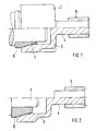
- the drive shaft 1 can be seen, for example, of an electric motor (not shown) which is to be coupled to a transmission.
- the coupling element 2 consists of the cup-shaped part 3 and the stub shaft 4, which is integrally connected to it, on which the pinion 5 is arranged.
- the pinion 5 is already the first stage of the transmission.
- the coupling between the drive shaft 1 and the coupling element 2 takes place by means of a non-positive connection between the cup-shaped part 3 and the drive shaft 1 with the interposition of the conical sleeve 6, i.e. the cup-shaped part 3 is shrunk onto the drive shaft 1 with the interposition of the conical sleeve 6.
- the conical sleeve 6 has also previously been shrunk onto the drive shaft 1, for example.
- the drive shaft 1 has a relatively large diameter, so that the conical sleeve 6 only has to bridge a relatively small joining gap between the inner surface of the cup-shaped part 3 and the drive shaft 1.
- the joining gap is larger because of the smaller diameter of the drive shaft 1.
- the conical sleeve 6 therefore has a greater wall thickness.
- the conical sleeve 6 has been adapted to this application in that it has been drilled out to a smaller inner diameter than the conical sleeve 6 in FIG. 1.
Landscapes
- Engineering & Computer Science (AREA)
- General Engineering & Computer Science (AREA)
- Mechanical Engineering (AREA)
- Shafts, Cranks, Connecting Bars, And Related Bearings (AREA)
- Connection Of Motors, Electrical Generators, Mechanical Devices, And The Like (AREA)
- Mechanical Operated Clutches (AREA)
Claims (2)
- Accouplement permanent entre un arbre menant (1) et un arbre mené, cet accouplement comprenant à son extrémité dirigée vers l'arbre menant (1) un élément d'accouplement (2) en forme d'arbre creux cylindrique, ainsi qu'une douille conique (6), fixée à l'arbre menant (1) par serrage, caractérisé par le fait que :a) l'élément d'accouplement (2) est constitué d'une partie en forme de coupe (3) et d'une extrémité de l'arbre (4) reliée à la base de cette coupe,b) l'extrémité ouverte du profil intérieur de la partie en forme de coupe (3) présente une forme conique pour la réception de la douille (6),c) la douille (6) contient, pour l'adaptation de l'accouplement à différents diamètres extérieurs des arbres, un alésage de centrage adapté à ceux-ci, tandis que sa forme conique extérieure reste inchangée.
- Accouplement permanent suivant la revendication 1,
caractérisé par le fait que la partie en forme de coupe (3) est liée à l'arbre menant (1) par frettage à chaud après intercalage de la douille conique (6).
Applications Claiming Priority (2)
| Application Number | Priority Date | Filing Date | Title |
|---|---|---|---|
| DE4312687 | 1993-04-20 | ||
| DE4312687A DE4312687A1 (de) | 1993-04-20 | 1993-04-20 | Permanente Kupplung zwischen zwei Wellen |
Publications (2)
| Publication Number | Publication Date |
|---|---|
| EP0621412A1 EP0621412A1 (fr) | 1994-10-26 |
| EP0621412B1 true EP0621412B1 (fr) | 1997-03-05 |
Family
ID=6485787
Family Applications (1)
| Application Number | Title | Priority Date | Filing Date |
|---|---|---|---|
| EP94105745A Expired - Lifetime EP0621412B1 (fr) | 1993-04-20 | 1994-04-14 | Accouplement permanent entre deux arbres |
Country Status (3)
| Country | Link |
|---|---|
| EP (1) | EP0621412B1 (fr) |
| DE (2) | DE4312687A1 (fr) |
| ES (1) | ES2102091T3 (fr) |
Families Citing this family (5)
| Publication number | Priority date | Publication date | Assignee | Title |
|---|---|---|---|---|
| DE19607735A1 (de) * | 1996-02-29 | 1997-09-04 | Siemens Ag | Verfahren zum Zusammenbau eines Kraftfahrzeug-Antriebes mit einem Elektromotor |
| DE19633169A1 (de) * | 1996-08-17 | 1998-02-19 | Teves Gmbh Alfred | Elektromotor-/Pumpenaggregat |
| GB9618244D0 (en) * | 1996-08-31 | 1996-10-09 | Allen Kenneth J | Improvements relating to rotary degassing of metals |
| DE10012723B4 (de) * | 2000-03-16 | 2005-03-10 | Webasto Ag Fahrzeugtechnik | Antrieb für ein verstellbares Fahrzeugteil |
| WO2016022478A1 (fr) * | 2014-08-04 | 2016-02-11 | Fluid Handling Llc | Agencement de levage d'arbre à rondelle conique |
Family Cites Families (3)
| Publication number | Priority date | Publication date | Assignee | Title |
|---|---|---|---|---|
| US3806267A (en) * | 1972-11-13 | 1974-04-23 | E Systems Inc | Coupling apparatus |
| US3836272A (en) * | 1973-07-02 | 1974-09-17 | Gen Motors Corp | Connecting device with expanding splines |
| CH590414A5 (fr) * | 1975-07-04 | 1977-08-15 | Bbc Brown Boveri & Cie |
-
1993
- 1993-04-20 DE DE4312687A patent/DE4312687A1/de not_active Withdrawn
-
1994
- 1994-04-14 DE DE59401875T patent/DE59401875D1/de not_active Expired - Fee Related
- 1994-04-14 ES ES94105745T patent/ES2102091T3/es not_active Expired - Lifetime
- 1994-04-14 EP EP94105745A patent/EP0621412B1/fr not_active Expired - Lifetime
Also Published As
| Publication number | Publication date |
|---|---|
| DE4312687A1 (de) | 1994-10-27 |
| DE59401875D1 (de) | 1997-04-10 |
| ES2102091T3 (es) | 1997-07-16 |
| EP0621412A1 (fr) | 1994-10-26 |
Similar Documents
| Publication | Publication Date | Title |
|---|---|---|
| EP0164792B1 (fr) | Dispositif pour l'accouplement positif de deux arbres | |
| EP0743479A1 (fr) | Arrangement pour la connexion d'un tuyau métallique dans un manchon d'insertion | |
| EP0952939B1 (fr) | Dispositif d'entrainement d'un systeme d'essuie-glace, notamment pour des vitres de vehicule | |
| EP0287791B1 (fr) | Raccord enfichable | |
| DE4333988A1 (de) | Rohrförmiges mechanisches Element, wie Kraftübertragungswelle eines Kraftfahrzeugs | |
| DE3014790C2 (de) | Zwischenlageranordnung, insbesondere für einen Gelenkwellenzug | |
| EP0621412B1 (fr) | Accouplement permanent entre deux arbres | |
| EP0575727A1 (fr) | Joint de tuyau | |
| DE3245041C2 (de) | Schwingungstilgeranordnung im Antriebsstrang von Kraftfahrzeugen | |
| EP0109451B1 (fr) | Arbre d'entraînement tubulaire en matière plastique renforcée de fibres avec pièces d'extrémités fixées par collage | |
| DE3143485C2 (fr) | ||
| EP0877173B1 (fr) | Arbre de transmission en plastic renforcé par des fibres | |
| EP0779699B1 (fr) | Accouplement magnétique pour une pompe centrifuge | |
| DE29708324U1 (de) | Kraftübertragungswelle aus faserverstärktem Kunststoff | |
| DE3330330A1 (de) | Formschluessiger zusammenschluss einer welle mit einem maschinenelement | |
| DE3419291C2 (fr) | ||
| WO1989008206A1 (fr) | Dispositif de fixation d'une bague sur un arbre | |
| DE3911258C2 (fr) | ||
| EP0719390A1 (fr) | Accouplement par ressort enroule pour deux arbres en alignement | |
| DE102011013783A1 (de) | Verbindungsanordnung für Bambusstäbe | |
| EP1427625B1 (fr) | Soupape a tiroir rotatif pour systemes de direction assistee | |
| EP0814292A2 (fr) | Raccord fileté pour tuyaux flexibles | |
| DE3128152A1 (de) | "kreuzgelenk" | |
| DE2724800B2 (fr) | ||
| DE3400993A1 (de) | Sicherheitslenkwelle aus innenwelle und aussenrohr |
Legal Events
| Date | Code | Title | Description |
|---|---|---|---|
| PUAI | Public reference made under article 153(3) epc to a published international application that has entered the european phase |
Free format text: ORIGINAL CODE: 0009012 |
|
| AK | Designated contracting states |
Kind code of ref document: A1 Designated state(s): DE ES FR GB IT |
|
| 17P | Request for examination filed |
Effective date: 19941205 |
|
| 17Q | First examination report despatched |
Effective date: 19950829 |
|
| GRAG | Despatch of communication of intention to grant |
Free format text: ORIGINAL CODE: EPIDOS AGRA |
|
| GRAH | Despatch of communication of intention to grant a patent |
Free format text: ORIGINAL CODE: EPIDOS IGRA |
|
| GRAH | Despatch of communication of intention to grant a patent |
Free format text: ORIGINAL CODE: EPIDOS IGRA |
|
| GRAA | (expected) grant |
Free format text: ORIGINAL CODE: 0009210 |
|
| AK | Designated contracting states |
Kind code of ref document: B1 Designated state(s): DE ES FR GB IT |
|
| REF | Corresponds to: |
Ref document number: 59401875 Country of ref document: DE Date of ref document: 19970410 |
|
| GBT | Gb: translation of ep patent filed (gb section 77(6)(a)/1977) |
Effective date: 19970415 |
|
| ITF | It: translation for a ep patent filed | ||
| ET | Fr: translation filed | ||
| REG | Reference to a national code |
Ref country code: ES Ref legal event code: FG2A Ref document number: 2102091 Country of ref document: ES Kind code of ref document: T3 |
|
| PLBE | No opposition filed within time limit |
Free format text: ORIGINAL CODE: 0009261 |
|
| STAA | Information on the status of an ep patent application or granted ep patent |
Free format text: STATUS: NO OPPOSITION FILED WITHIN TIME LIMIT |
|
| 26N | No opposition filed | ||
| PGFP | Annual fee paid to national office [announced via postgrant information from national office to epo] |
Ref country code: GB Payment date: 20000324 Year of fee payment: 7 |
|
| PGFP | Annual fee paid to national office [announced via postgrant information from national office to epo] |
Ref country code: FR Payment date: 20000328 Year of fee payment: 7 |
|
| PGFP | Annual fee paid to national office [announced via postgrant information from national office to epo] |
Ref country code: ES Payment date: 20000418 Year of fee payment: 7 |
|
| PGFP | Annual fee paid to national office [announced via postgrant information from national office to epo] |
Ref country code: DE Payment date: 20000630 Year of fee payment: 7 |
|
| PG25 | Lapsed in a contracting state [announced via postgrant information from national office to epo] |
Ref country code: GB Free format text: LAPSE BECAUSE OF NON-PAYMENT OF DUE FEES Effective date: 20010414 |
|
| PG25 | Lapsed in a contracting state [announced via postgrant information from national office to epo] |
Ref country code: ES Free format text: LAPSE BECAUSE OF NON-PAYMENT OF DUE FEES Effective date: 20010415 |
|
| PG25 | Lapsed in a contracting state [announced via postgrant information from national office to epo] |
Ref country code: FR Free format text: THE PATENT HAS BEEN ANNULLED BY A DECISION OF A NATIONAL AUTHORITY Effective date: 20010430 |
|
| GBPC | Gb: european patent ceased through non-payment of renewal fee |
Effective date: 20010414 |
|
| PG25 | Lapsed in a contracting state [announced via postgrant information from national office to epo] |
Ref country code: DE Free format text: LAPSE BECAUSE OF NON-PAYMENT OF DUE FEES Effective date: 20020201 |
|
| REG | Reference to a national code |
Ref country code: FR Ref legal event code: ST |
|
| REG | Reference to a national code |
Ref country code: ES Ref legal event code: FD2A Effective date: 20020514 |
|
| PG25 | Lapsed in a contracting state [announced via postgrant information from national office to epo] |
Ref country code: IT Free format text: LAPSE BECAUSE OF NON-PAYMENT OF DUE FEES;WARNING: LAPSES OF ITALIAN PATENTS WITH EFFECTIVE DATE BEFORE 2007 MAY HAVE OCCURRED AT ANY TIME BEFORE 2007. THE CORRECT EFFECTIVE DATE MAY BE DIFFERENT FROM THE ONE RECORDED. Effective date: 20050414 |