EP0621529A2 - Verfahren und Anordnung zur Datenaufzeichnung auf eine wiederbeschreibbare optische Platte - Google Patents
Verfahren und Anordnung zur Datenaufzeichnung auf eine wiederbeschreibbare optische Platte Download PDFInfo
- Publication number
- EP0621529A2 EP0621529A2 EP94302476A EP94302476A EP0621529A2 EP 0621529 A2 EP0621529 A2 EP 0621529A2 EP 94302476 A EP94302476 A EP 94302476A EP 94302476 A EP94302476 A EP 94302476A EP 0621529 A2 EP0621529 A2 EP 0621529A2
- Authority
- EP
- European Patent Office
- Prior art keywords
- data
- partition
- driver
- block
- optical disk
- Prior art date
- Legal status (The legal status is an assumption and is not a legal conclusion. Google has not performed a legal analysis and makes no representation as to the accuracy of the status listed.)
- Withdrawn
Links
Images


Classifications
-
- G—PHYSICS
- G11—INFORMATION STORAGE
- G11B—INFORMATION STORAGE BASED ON RELATIVE MOVEMENT BETWEEN RECORD CARRIER AND TRANSDUCER
- G11B7/00—Recording or reproducing by optical means, e.g. recording using a thermal beam of optical radiation by modifying optical properties or the physical structure, reproducing using an optical beam at lower power by sensing optical properties; Record carriers therefor
- G11B7/004—Recording, reproducing or erasing methods; Read, write or erase circuits therefor
- G11B7/0045—Recording
-
- G—PHYSICS
- G06—COMPUTING OR CALCULATING; COUNTING
- G06F—ELECTRIC DIGITAL DATA PROCESSING
- G06F3/00—Input arrangements for transferring data to be processed into a form capable of being handled by the computer; Output arrangements for transferring data from processing unit to output unit, e.g. interface arrangements
- G06F3/06—Digital input from, or digital output to, record carriers, e.g. RAID, emulated record carriers or networked record carriers
- G06F3/0601—Interfaces specially adapted for storage systems
- G06F3/0602—Interfaces specially adapted for storage systems specifically adapted to achieve a particular effect
- G06F3/0614—Improving the reliability of storage systems
- G06F3/0619—Improving the reliability of storage systems in relation to data integrity, e.g. data losses, bit errors
-
- G—PHYSICS
- G06—COMPUTING OR CALCULATING; COUNTING
- G06F—ELECTRIC DIGITAL DATA PROCESSING
- G06F3/00—Input arrangements for transferring data to be processed into a form capable of being handled by the computer; Output arrangements for transferring data from processing unit to output unit, e.g. interface arrangements
- G06F3/06—Digital input from, or digital output to, record carriers, e.g. RAID, emulated record carriers or networked record carriers
- G06F3/0601—Interfaces specially adapted for storage systems
- G06F3/0628—Interfaces specially adapted for storage systems making use of a particular technique
- G06F3/0638—Organizing or formatting or addressing of data
- G06F3/0644—Management of space entities, e.g. partitions, extents, pools
-
- G—PHYSICS
- G06—COMPUTING OR CALCULATING; COUNTING
- G06F—ELECTRIC DIGITAL DATA PROCESSING
- G06F3/00—Input arrangements for transferring data to be processed into a form capable of being handled by the computer; Output arrangements for transferring data from processing unit to output unit, e.g. interface arrangements
- G06F3/06—Digital input from, or digital output to, record carriers, e.g. RAID, emulated record carriers or networked record carriers
- G06F3/0601—Interfaces specially adapted for storage systems
- G06F3/0628—Interfaces specially adapted for storage systems making use of a particular technique
- G06F3/0646—Horizontal data movement in storage systems, i.e. moving data in between storage devices or systems
- G06F3/0652—Erasing, e.g. deleting, data cleaning, moving of data to a wastebasket
-
- G—PHYSICS
- G06—COMPUTING OR CALCULATING; COUNTING
- G06F—ELECTRIC DIGITAL DATA PROCESSING
- G06F3/00—Input arrangements for transferring data to be processed into a form capable of being handled by the computer; Output arrangements for transferring data from processing unit to output unit, e.g. interface arrangements
- G06F3/06—Digital input from, or digital output to, record carriers, e.g. RAID, emulated record carriers or networked record carriers
- G06F3/0601—Interfaces specially adapted for storage systems
- G06F3/0668—Interfaces specially adapted for storage systems adopting a particular infrastructure
- G06F3/0671—In-line storage system
- G06F3/0683—Plurality of storage devices
- G06F3/0686—Libraries, e.g. tape libraries, jukebox
-
- G—PHYSICS
- G11—INFORMATION STORAGE
- G11B—INFORMATION STORAGE BASED ON RELATIVE MOVEMENT BETWEEN RECORD CARRIER AND TRANSDUCER
- G11B20/00—Signal processing not specific to the method of recording or reproducing; Circuits therefor
- G11B20/10—Digital recording or reproducing
-
- G—PHYSICS
- G11—INFORMATION STORAGE
- G11B—INFORMATION STORAGE BASED ON RELATIVE MOVEMENT BETWEEN RECORD CARRIER AND TRANSDUCER
- G11B27/00—Editing; Indexing; Addressing; Timing or synchronising; Monitoring; Measuring tape travel
- G11B27/002—Programmed access in sequence to a plurality of record carriers or indexed parts, e.g. tracks, thereof, e.g. for editing
-
- G—PHYSICS
- G11—INFORMATION STORAGE
- G11B—INFORMATION STORAGE BASED ON RELATIVE MOVEMENT BETWEEN RECORD CARRIER AND TRANSDUCER
- G11B27/00—Editing; Indexing; Addressing; Timing or synchronising; Monitoring; Measuring tape travel
- G11B27/02—Editing, e.g. varying the order of information signals recorded on, or reproduced from, record carriers
- G11B27/031—Electronic editing of digitised analogue information signals, e.g. audio or video signals
- G11B27/036—Insert-editing
-
- G—PHYSICS
- G11—INFORMATION STORAGE
- G11B—INFORMATION STORAGE BASED ON RELATIVE MOVEMENT BETWEEN RECORD CARRIER AND TRANSDUCER
- G11B27/00—Editing; Indexing; Addressing; Timing or synchronising; Monitoring; Measuring tape travel
- G11B27/10—Indexing; Addressing; Timing or synchronising; Measuring tape travel
- G11B27/11—Indexing; Addressing; Timing or synchronising; Measuring tape travel by using information not detectable on the record carrier
-
- G—PHYSICS
- G11—INFORMATION STORAGE
- G11B—INFORMATION STORAGE BASED ON RELATIVE MOVEMENT BETWEEN RECORD CARRIER AND TRANSDUCER
- G11B27/00—Editing; Indexing; Addressing; Timing or synchronising; Monitoring; Measuring tape travel
- G11B27/10—Indexing; Addressing; Timing or synchronising; Measuring tape travel
- G11B27/19—Indexing; Addressing; Timing or synchronising; Measuring tape travel by using information detectable on the record carrier
- G11B27/28—Indexing; Addressing; Timing or synchronising; Measuring tape travel by using information detectable on the record carrier by using information signals recorded by the same method as the main recording
- G11B27/32—Indexing; Addressing; Timing or synchronising; Measuring tape travel by using information detectable on the record carrier by using information signals recorded by the same method as the main recording on separate auxiliary tracks of the same or an auxiliary record carrier
- G11B27/327—Table of contents
- G11B27/329—Table of contents on a disc [VTOC]
-
- G—PHYSICS
- G11—INFORMATION STORAGE
- G11B—INFORMATION STORAGE BASED ON RELATIVE MOVEMENT BETWEEN RECORD CARRIER AND TRANSDUCER
- G11B2220/00—Record carriers by type
- G11B2220/20—Disc-shaped record carriers
- G11B2220/21—Disc-shaped record carriers characterised in that the disc is of read-only, rewritable, or recordable type
- G11B2220/215—Recordable discs
- G11B2220/216—Rewritable discs
-
- G—PHYSICS
- G11—INFORMATION STORAGE
- G11B—INFORMATION STORAGE BASED ON RELATIVE MOVEMENT BETWEEN RECORD CARRIER AND TRANSDUCER
- G11B2220/00—Record carriers by type
- G11B2220/20—Disc-shaped record carriers
- G11B2220/25—Disc-shaped record carriers characterised in that the disc is based on a specific recording technology
- G11B2220/2525—Magneto-optical [MO] discs
-
- G—PHYSICS
- G11—INFORMATION STORAGE
- G11B—INFORMATION STORAGE BASED ON RELATIVE MOVEMENT BETWEEN RECORD CARRIER AND TRANSDUCER
- G11B2220/00—Record carriers by type
- G11B2220/40—Combinations of multiple record carriers
- G11B2220/41—Flat as opposed to hierarchical combination, e.g. library of tapes or discs, CD changer, or groups of record carriers that together store one title
-
- G—PHYSICS
- G11—INFORMATION STORAGE
- G11B—INFORMATION STORAGE BASED ON RELATIVE MOVEMENT BETWEEN RECORD CARRIER AND TRANSDUCER
- G11B2220/00—Record carriers by type
- G11B2220/60—Solid state media
- G11B2220/65—Solid state media wherein solid state memory is used for storing indexing information or metadata
-
- G—PHYSICS
- G11—INFORMATION STORAGE
- G11B—INFORMATION STORAGE BASED ON RELATIVE MOVEMENT BETWEEN RECORD CARRIER AND TRANSDUCER
- G11B27/00—Editing; Indexing; Addressing; Timing or synchronising; Monitoring; Measuring tape travel
- G11B27/02—Editing, e.g. varying the order of information signals recorded on, or reproduced from, record carriers
- G11B27/031—Electronic editing of digitised analogue information signals, e.g. audio or video signals
- G11B27/034—Electronic editing of digitised analogue information signals, e.g. audio or video signals on discs
Definitions
- the present invention relates to rewritable (erasable) optical disks and, in particular, to a method and apparatus for reducing the data integrity exposure and negative performance impact of separate erase and write passes when writing data to such a disk.
- the recording surface of optical disks like the recording surface of magnetic disks, is divided into a series of data recording tracks (concentric or spiral) having a common rotational center. Each track is subdivided into sectors; data is typically written to and read from a disk in logical blocks.
- block will refer to the data
- ctor will refer to a physical location on a disk to which a single block of data can be written.
- Data can include directories, volume table of contents and control structures, as well as user or file data (collectively referred to herein as file system data) and maintained by file system software.
- the logical block structures used by the present invention are implemented and maintained by driver software at a system level below the file system software (through which the user interacts with the system).
- certain optical media such as magneto-optical (MO) and phase change disks
- MO magneto-optical
- phase change disks are rewritable but currently require that data previously recorded onto a particular sector of the disk be erased before a new or revised block of data is recorded on that sector. Therefore, writing new or revised data onto a sector of such a disk requires a first rotation or pass of the disk while the sector (containing obsolete data) is erased and a second rotation while the data is written. Verification is generally desired and may require a third rotation.
- a significant disadvantage of the erase-before-write procedure is that the integrity of revised data to be written to the disk is jeopardized between the erase pass and the write pass. If, for example, power is lost or the system fails during this time, the data to be written will be lost from the memory of the processor or drive controller, but the original version of the data, just erased from the disk, will also be lost thereby impeding recovery.
- the erase-before-write procedure presents an additional disadvantage.
- delays are also incurred while the optical head moves radially inwardly or outwardly seeking the desired track for the erase pass (seek delay) and while the head waits for the desired sector on the track to rotate into position opposite the head for the erase, write and verify operations (latency delay).
- the three-pass erase-write-verify procedure is typically performed separately for each block of data to be written (or group of blocks destined for contiguous sectors) and seek and latency delays can cause a significant performance degradation.
- a file control program at the file system level includes a command to pre-erase destination sectors containing original, to-be-revised, data so that the new or revised data is written onto the sector in a two-pass write-verify process.
- a method only reduces the delays; it does nothing to enhance data integrity.
- Another proposed solution would pre-erase sectors containing obsolete data (but not the sectors containing the original data), write the new or revised data to the erased sectors and then erase the original data. While this method may reduce the risk of data loss, it does nothing to reduce the delays and requires complicated directory maintenance to keep track of multiple versions of data on the same disk.
- solutions of both types can entail substantial development costs, may not fit naturally or transparently into the intended operating system, may not be portable to other environments with different file system semantics and may only protect file data ("user" data) but not system control data.
- the present invention provides apparatus for recording data on a rewritable optical disk when the disk is mounted in a disk drive, the apparatus comprising: means for establishing a driver partition in a nonvolatile storage buffer; means for erasing a first portion of the driver partition; means for receiving from a file system a block of file system data to be recorded in a predetermined target sector of a logical partition of a rewritable optical disk when it is mounted in a disk drive; means for storing the block of file system data in the first portion of the driver partition; means for storing a second portion of the driver partition mapping information identifying the target sector in the logical partition; and means for background processing the stored block of data, including means for erasing the target sector and for copying the stored block of data from the first portion of the driver partition to the erased target sector.
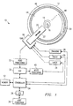
- Fig. 1 is a block diagram of the recording system 10 of the present invention and includes a representation of a rewritable optical disk 12.
- the disk 12 includes a continuous spiral track 14 (although it is also known to use concentric circular tracks) around a central hub 16, Not shown are a spindle onto which the disk 12 can be mounted or a spindle motor for rotating the disk 12.
- the disk 12 can be permanently mounted on the spindle in a disk drive or can be removably mounted in the drive.
- An optical read/write head 18 includes a head arm 20 proximate to one surface of the disk 12 and transporting various optical elements radially relative to the hub 16 (that is, in the directions indicated by the arrow 22).
- the head 18 includes an optical path coupled to a laser 24 which provides a laser beam for reading or erasing data from, and writing data to, the disk 12. Focus and tracking units 26 and 28, respectively, control coarse and fine actuators in the head 18 to enable the laser beam to access and precisely follow a desired portion of the track 14.
- Data read from the disk 12 is processed by a read processor 30 and an error correction code (ECC) processor 32 before being transmitted to a drive controller or processor 34.
- ECC error correction code
- the controller 34 sends the data through an interface device 36 to a host processor 38, such as a control unit, personal computer, large system computer, communications system or the like. Reversing the foregoing process to write data, data is transmitted by the host 38 through the interface 36 to the controller 34.
- the controller 34 sends the data through the ECC processor 32 to be processed by a write processor 40 before being written to the disk 12.
- the laser 24 and focus and tracking units 26 and 28 are also interconnected with, and controlled by, the controller 34 which can include a memory 42 for holding control programs and data.
- File system data (user data as well as control data) are read, processed, written and transmitted in logical blocks, each corresponding in size (in bytes) to a physical sector of the disk 12.
- Information associated with each data block indicates the destination address (the target sector) of the data block in a logical partition 44 of the disk 12.
- File system software such as executed on the host 38, organizes the data and establishes the correct destination addresses.
- the present invention includes driver level software (hereinafter referred to as the "driver") operating below and independent of the file system software to establish a driver partition, separate from the logical partition 44, for temporarily maintaining blocks of data destined for the logical partition 44.
- the driver can reside, for example, in an operating system (such as Unix or OS/2) device driver, in microcode in the optical drive itself, in the logical volume manager in AIX, split between a hardware driver and the logical volume manager, or in software in an automated optical library controller (UNIX is a registered trade mark of UNIX Systems Laboratories Inc).
- the driver partition is established on any non-volatile device, including the same optical disk 12 on which the logical partition 44 is located, a separate optical disk, magnetic media or non-volatile random access memory. Thus, if a power failure or other system fault occurs, the data stored in the driver partition will remain intact and can be recovered later when the system returns to normal.
- the driver partition comprises space for data blocks and control information. It is believed that a partition size of about ten percent of the size of the logical partition which its serves provides efficient operation; however, the actual size is not critical. Although the driver partition will be described as residing on the same media as the logical partition, the description is equally applicable to driver partitions established on other non-volatile devices.
- a pending write entry (PWE) area 46 comprises the bulk of the driver partition and includes pre-erased space to store blocks of data from the host 38.
- a separate PWE is created for each block and includes header information, specifying the size and target address of the data, and the data itself.
- the PWE's are stored sequentially in entry areas in the PWE area 46; a later stored block destined for the same target sector as an earlier stored block supersedes the earlier stored data. This ensures that only the most recent data in the PWE area 46 is valid and is eventually copied to the logical partition 44.
- the driver can redirect the command and determine whether the desired data is in the PWE area 46. If it is, the most current version of the desired data is read and transmitted to the host 38 while earlier, invalid (obsolete) versions are ignored. If the desired data is not in the PWE area 46, it is read directly from the logical partition. Thus, the driver partition has cache-like characteristics.
- the second structure in the driver partition is a map 48 which includes an entry for each PWE in the PWE area 46 indicating the size of the PWE, its location in the PWE area 46 and its target sector in the logical partition 44.
- a control block structure 50 is also maintained in the driver partition to determine the status of the map 48 and the location of the next available erased entry area in the PWE area 46.
- the map status is indicated by a "valid" flag having a TRUE state to indicate that the information in the map 48 is up to date and a FALSE state to indicate that the information has been corrupted or is otherwise obsolete. It will be appreciated that the sizes and locations of the logical partition 44, the PWE area 46, the map 48 and the control block 50 shown in Fig. 1 on the disk 12 are for illustrative purposes only and are not intended to represent their actual sizes or locations.
- the optical disk 12 is mounted in a drive (Step 200, Fig. 2A), the driver reads the control block structure 50 from the driver partition (Step 202) and checks the status of the valid flag (Step 204). If the flag is set to TRUE, the map structure 48 in the driver partition is valid (current) and can be read from the driver partition into a memory device, such as the memory 42 (Fig. 1) or, to prevent loss of mapping information, to a non-volatile random access memory.
- a memory device such as the memory 42 (Fig. 1) or, to prevent loss of mapping information, to a non-volatile random access memory.
- the flag is set to FALSE (Step 206) indicating that the map in the driver partition is no longer current but has been superseded by the in-memory map which will be kept current during subsequent operations, and the map structure written to the memory (Step 208). If the flag is FALSE when originally checked (Step 204), the map structure 48 is deemed to be faulty; the PWE headers must be read by the driver (Step 210) until an erased entry area is located (Step 212), thereby rebuilding the map 48 (Step 214). This updated map is then written to the in-memory map (Step 208).
- the system receives a block of file system data from the host (Step 218, Fig. 2B) and determines whether the system is in a stream mode (Step 220).
- the stream mode is enabled when the logical partition 44 is to be stream filled (that is, when large amounts of data destined for consecutive target sectors or tracks are to be written in a single write operation) or when the amount of data to be written could exceed the capacity of the driver partition. If the stream mode is enabled, the appropriate sectors in the logical partition 44 are erased, if necessary, and the data stream written directly to them by the drive (Step 222).
- a verify pass typically follows the write pass.
- Step 224 If the stream mode is not enabled, the system generates a corresponding PWE (Step 224) which is written to the next available entry area in the driver partition (Step 226).
- the in-memory map is then updated (Step 228) with information about the new PWE.
- the system determines whether the user has requested that the disk 12 be unmounted (Step 300, Fig. 3).
- the "user" can be a human computer operator in an automated environment or can be a library controller in a library environment (as will be described more fully below in conjunction with Fig. 5).
- the in-memory map must be written to the map structure 48 of the driver partition (Step 302).
- the valid flag is then set to TRUE (Step 304) and written to the control block 50; the disk is then ejected from the drive (Step 306) and the operation is completed.
- Step 400 Keeping unused entry areas in the PWE area 46 erased in anticipation of later write operations reduces the total seek and latency delays by eliminating the erase pass during a write and frees the host 38 more quickly for other tasks. Further increases in speed and efficiency are achieved in the present invention with background processing of the PWE's (Steps 400 and 402, Fig. 4A), transparently without requiring user or host intervention and without delaying or otherwise affecting host operations. Three modes of background processing are discussed herein as examples; other background modes can also be employed. For concurrent background operations, after receiving a read-block request from the host (Step 404, Fig. 4B), the system determines whether the data requested is in the driver partition (Step 406).
- Step 410 the system determines whether a "piggy-back" mode is enabled. Such a mode permits piggy-backing erase and write operations involving PWE's onto sector seek operations during host initiated data read, write, erase and verify operations. If the driver determines that a seek has been initiated by the host 38, the in-memory map is checked to determine whether any PWE in the driver partition is destined for a sector located "near" the seek-to sector (that is, the sector to be erased, read from, written to or verified) (Step 412).
- “Near” can be a defined distance based upon the seek performance characteristics of the drive. The optimal value can be determined experimentally for a given environment an can be, for example, plus or minus about thirty tracks. If a target sector is near the seek-to sector, the driver determines whether the target sector contains obsolete data and needs to be erased (Step 414). If so, the erasure is accomplished while the optical head 18 seeks to the near sector (Step 416) and copying the PWE to the target sector occurs later. If the target was previously erased, the PWE is copied from the driver partition to the target sector after the optical head 18 seeks to the near sector (Step 418) and the in-memory map updated (Step 240). If the piggy-back mode is not on, the system seeks to, and returns, the requested data (Steps 422 and 424) when the drive is available.
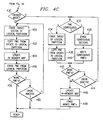
- Packing can also be accommodated in the background when write operations of multiple blocks of data will affect contiguous sectors. If packing is enabled (Step 430, Fig. 4C), the in-memory map is checked for PWE's destined for contiguous target sectors in the logical partition 44 (Step 432). If there are none, the target sector partition is erased (Step 434) and the PWE is copied from the driver partition to the logical partition (Step 436). If there are PWE's destined for contiguous target sectors, the contiguous target sectors are erased from the logical partition 44 (Step 438) and the PWE's copied from the driver partition to the logical partition 44 (Step 440).
- Step 442 a determination is made whether additional PWE's remain to be processed (Step 442). If so, and if the drive is inactive (Step 444), the packed-mode PWE processing is repeated (beginning with Step 432). If no further PWE's remain to be processed, or if the drive is active, the in-memory map is updated and the moved PWE's are erased (Step 448).
- Step 450 a target sector of a PWE in the driver partition is erased (Step 450) and the PWE copied to the erased sector (Step 454).
- the in-memory map is updated to indicate that PWE's have been successfully copied to the logical partition 44 of the disk 12.
- Step 456 the control block 50 is then updated to reflect the availability of the newly erased entry area. This step can be performed after updating the in-memory map or whenever the disk is otherwise inactive.
- Step 456 Following the erasure of obsolete PWE's (Step 456), additional blocks of data can be received (Step 458) and the just described process repeats when the drive is inactive (Step 460).
- the present invention can be employed in either a stand-alone (non-automated) environment or can be incorporated into an automated storage and retrieval library 500 as shown in Fig. 5.
- the library 500 includes a library controller 502 interconnected with a host processor 504.
- One or more optical disk drives 506 and an autochanger or a mechanical accessor 508 are also interconnected with the controller 502 Such interconnection can be made with a single bus, such as a SCSI bus, or with separate buses for the drives 506 and the accessor 508.
- the controller 502 directs the accessor 508 to locate and retrieve the cartridge from its storage cell in a bank of cells 510 and mount the cartridge in one of the drives 506. When the cartridge is no longer needed, the accessor 508 is directed to replace it in the original or another cell 510.
- the driver partition in the library 500 can be located on the same optical disk as the logical partition, in non-volatile random access memory (such as in the library controller 502) or on separate magnetic media.
- the driver partition can be located on a dedicated optical disk in the library 500, preferably kept mounted in one of the disk drives 506 and used to maintain PWE's for many disks. Appropriate microcode or software instructions ensure that PWE's are copied to the correct sectors of the correct disks.
- the apparatus and method do not require large development costs, are substantially transparent to the host operating system, which can be portable to different operating environments and which will protect system control data as well as user data.
- the system includes means for establishing a driver partition in a non-volatile storage buffer, means for receiving from a file system a block of file system data to be recorded in a predetermined target sector of a logical partition of a rewritable optical disk, means for storing the block of data in the first portion of the driver partition, means for storing in a second portion of the driver partition information identifying the target sector and means for background processing of the block of data.
- the background processing means includes means for erasing the target sector and for copying the block of data from the first portion of the driver partition to the erased target sector.
- the non-volatile storage buffer can be located on the optical disk itself or can be on a separate device, such as non-volatile random access memory or magnetic media.
- the system can be incorporated into an automated optical storage and retrieval (library) unit comprising one or more optical drives, numerous disk storage cells and a mechanical accessor for automatically mounting disk cartridges from the storage cells into the drives and replacing them.
- library automated optical storage and retrieval
- the non-volatile storage buffer can be located on a dedicated optical disk different from the disk on which is located the logical partition with the target sector.
- the driver partition is established and maintained by driver software at a level below the file system. It is transparent to the user and data transfers from the driver partition to target sectors occur in the background during otherwise "dead" time for the drive.
- the present invention resolves the integrity/speed tradeoff, eliminating data exposure between the erase and write passes while enhancing performance by eliminating the erase pass immediately before a write. Because the present invention operates at the driver level, rather than the file system level, it is flexible and portable, not dependent upon any particular operating environment or application.
- a system for recording information on a rewritable optical disk which comprises: a controller; a disk drive, interconnected with said controller, for recording blocks of file system data onto predetermined target sectors of a rewritable optical disk mounted therein; a non-volatile driver partition having a pending write entry area and a map area; and a machine executable driver for directing that the blocks of data be stored in entry areas of said pending write entry area, directing that mapping information identifying the target sectors be stored in said map area, directing that the target sectors be erased and directing that the blocks of data be copied from the entry areas to the erased target sectors in the background.
Landscapes
- Engineering & Computer Science (AREA)
- Theoretical Computer Science (AREA)
- Human Computer Interaction (AREA)
- Physics & Mathematics (AREA)
- General Engineering & Computer Science (AREA)
- General Physics & Mathematics (AREA)
- Multimedia (AREA)
- Library & Information Science (AREA)
- Computer Security & Cryptography (AREA)
- Signal Processing (AREA)
- Signal Processing For Digital Recording And Reproducing (AREA)
- Optical Recording Or Reproduction (AREA)
- Management Or Editing Of Information On Record Carriers (AREA)
Applications Claiming Priority (2)
| Application Number | Priority Date | Filing Date | Title |
|---|---|---|---|
| US49470 | 1993-04-20 | ||
| US08/049,470 US5537578A (en) | 1993-04-20 | 1993-04-20 | Transparent driving partition for processing logical volumes to be recorded onto optical media |
Publications (2)
| Publication Number | Publication Date |
|---|---|
| EP0621529A2 true EP0621529A2 (de) | 1994-10-26 |
| EP0621529A3 EP0621529A3 (de) | 1995-12-06 |
Family
ID=21959996
Family Applications (1)
| Application Number | Title | Priority Date | Filing Date |
|---|---|---|---|
| EP94302476A Withdrawn EP0621529A3 (de) | 1993-04-20 | 1994-04-07 | Verfahren und Anordnung zur Datenaufzeichnung auf eine wiederbeschreibbare optische Platte. |
Country Status (4)
| Country | Link |
|---|---|
| US (1) | US5537578A (de) |
| EP (1) | EP0621529A3 (de) |
| JP (1) | JP2700129B2 (de) |
| KR (1) | KR0136708B1 (de) |
Cited By (2)
| Publication number | Priority date | Publication date | Assignee | Title |
|---|---|---|---|---|
| US5787068A (en) * | 1996-11-07 | 1998-07-28 | Imation Corp. | Method and arrangement for preventing unauthorized duplication of optical discs using barriers |
| US6996667B2 (en) | 2002-07-30 | 2006-02-07 | Kabushiki Kaisha Toshiba | Method and apparatus for rewriting program executed in disk drive |
Families Citing this family (12)
| Publication number | Priority date | Publication date | Assignee | Title |
|---|---|---|---|---|
| KR100529485B1 (ko) * | 1997-09-02 | 2005-11-22 | 소니 가부시끼 가이샤 | 디지털 기록매체에 있어서의 애프터 레코딩 방법 및 장치 및그 디지털 기록 매체의 재생 방법 및 장치 |
| CN1163891C (zh) * | 1998-02-17 | 2004-08-25 | 松下电器产业株式会社 | 图像和/或声音记录装置 |
| US6697308B1 (en) | 2000-04-28 | 2004-02-24 | Mosel Vitelic Corporation | Method and system for providing timing adjustment to perform reliable optical recording at high speeds |
| US6721868B1 (en) * | 2000-08-09 | 2004-04-13 | Intel Corporation | Redirecting memory accesses for headless systems |
| US6574705B1 (en) | 2000-11-16 | 2003-06-03 | International Business Machines Corporation | Data processing system and method including a logical volume manager for storing logical volume data |
| US6643755B2 (en) * | 2001-02-20 | 2003-11-04 | Koninklijke Philips Electronics N.V. | Cyclically sequential memory prefetch |
| US6983292B1 (en) * | 2001-07-10 | 2006-01-03 | Sonic Solutions, Inc. | Method and apparatus for formatting and initialization of re-writable optical media |
| US7117230B1 (en) * | 2001-07-10 | 2006-10-03 | Sonic Solutions, Inc. | Method and apparatus for formatting and initialization of re-writable optical media using multiple tracks |
| US7177990B1 (en) * | 2002-05-21 | 2007-02-13 | Sonic Solutions | Automatic format of removable media |
| KR100809069B1 (ko) * | 2006-11-03 | 2008-03-03 | 삼성전자주식회사 | 비휘발성 메모리를 구비하는 광학 매체 드라이브 및 그구동 방법 |
| US9619157B2 (en) * | 2014-04-03 | 2017-04-11 | Analysis Solution Llc | High-speed data storage |
| US10658045B1 (en) * | 2019-05-15 | 2020-05-19 | Western Digital Technologies, Inc. | Enhanced solid-state drive write performance with background erase |
Family Cites Families (18)
| Publication number | Priority date | Publication date | Assignee | Title |
|---|---|---|---|---|
| JPS5832236A (ja) * | 1981-08-18 | 1983-02-25 | Matsushita Electric Ind Co Ltd | 光学的記録再生装置 |
| US5062009A (en) * | 1985-03-19 | 1991-10-29 | Canon Kabushiki Kaisha | Recording and/or reproducing apparatus having, in addition to a recording medium, memory means for memorizing information reproduced from the recording medium |
| JPS61233468A (ja) * | 1985-04-08 | 1986-10-17 | Hitachi Ltd | 回転型情報記録媒体への情報書込み制御方式 |
| JPH077329B2 (ja) * | 1985-07-29 | 1995-01-30 | 株式会社日立製作所 | 光ディスクメモリの情報書換え制御方法及び装置 |
| JPS6398889A (ja) * | 1986-10-14 | 1988-04-30 | Oki Electric Ind Co Ltd | 光デイスクフアイル装置 |
| US4953122A (en) * | 1986-10-31 | 1990-08-28 | Laserdrive Ltd. | Pseudo-erasable and rewritable write-once optical disk memory system |
| US4984103A (en) * | 1987-12-07 | 1991-01-08 | Fujitsu America, Inc. | Method for reading/writing for a floppy disc drive with buffer memory |
| US4939598A (en) * | 1988-02-08 | 1990-07-03 | International Business Machines Corporation | Managing data storage space on large capacity record media |
| JPH02203480A (ja) * | 1989-01-31 | 1990-08-13 | Nec Corp | 磁気ディスク制御装置 |
| FR2650391B1 (fr) * | 1989-07-27 | 1993-07-16 | Durand Alain | Procede de fabrication ou de rehabilitation d'un reservoir de stockage, reservoirs obtenus |
| JP3057498B2 (ja) * | 1989-08-02 | 2000-06-26 | 富士通株式会社 | アレイディスク装置およびそのデータ読み出し方法 |
| JP2775956B2 (ja) * | 1990-02-14 | 1998-07-16 | ソニー株式会社 | 記録媒体 |
| US5210866A (en) * | 1990-09-12 | 1993-05-11 | Storage Technology Corporation | Incremental disk backup system for a dynamically mapped data storage subsystem |
| JPH04291056A (ja) * | 1991-03-20 | 1992-10-15 | Matsushita Electric Ind Co Ltd | 光ディスク装置及びその再生方法 |
| US5325523A (en) * | 1991-04-10 | 1994-06-28 | International Business Machines Corporation | Method for deleting objects from library resident optical disks by accumulating pending delete requests |
| JPH04337546A (ja) * | 1991-05-14 | 1992-11-25 | Fujitsu Ltd | 磁気記録領域を備えたcdーrom及びドライブ装置 |
| US5239659A (en) * | 1991-06-19 | 1993-08-24 | Storage Technology Corporation | Phantom duplex copy group apparatus for a disk drive array data storge subsystem |
| US5287459A (en) * | 1991-10-03 | 1994-02-15 | International Business Machines Corporation | Method and apparatus for reducing response time in automated library data retrieval systems |
-
1993
- 1993-04-20 US US08/049,470 patent/US5537578A/en not_active Expired - Lifetime
-
1994
- 1994-03-02 JP JP6032175A patent/JP2700129B2/ja not_active Expired - Fee Related
- 1994-03-18 KR KR1019940005418A patent/KR0136708B1/ko not_active Expired - Fee Related
- 1994-04-07 EP EP94302476A patent/EP0621529A3/de not_active Withdrawn
Cited By (3)
| Publication number | Priority date | Publication date | Assignee | Title |
|---|---|---|---|---|
| US5787068A (en) * | 1996-11-07 | 1998-07-28 | Imation Corp. | Method and arrangement for preventing unauthorized duplication of optical discs using barriers |
| US6996667B2 (en) | 2002-07-30 | 2006-02-07 | Kabushiki Kaisha Toshiba | Method and apparatus for rewriting program executed in disk drive |
| SG129246A1 (en) * | 2002-07-30 | 2007-02-26 | Toshiba Kk | Method and apparatus for rewriting program executed in disk drive |
Also Published As
| Publication number | Publication date |
|---|---|
| JPH06325362A (ja) | 1994-11-25 |
| KR0136708B1 (ko) | 1998-05-15 |
| EP0621529A3 (de) | 1995-12-06 |
| US5537578A (en) | 1996-07-16 |
| KR940024696A (ko) | 1994-11-18 |
| JP2700129B2 (ja) | 1998-01-19 |
Similar Documents
| Publication | Publication Date | Title |
|---|---|---|
| US7774540B2 (en) | Storage system and method for opportunistic write-verify | |
| EP0357464B1 (de) | Informationsaufzeichnungs- und -wiedergabegerät mit optischen Speicherplatten | |
| US6757781B2 (en) | Buffer management system for managing the transfer of data into and out of a buffer in a disc drive | |
| US8200922B2 (en) | Storage system snapshot assisted by SSD technology | |
| US5537578A (en) | Transparent driving partition for processing logical volumes to be recorded onto optical media | |
| US6735678B2 (en) | Method and apparatus for disc drive defragmentation | |
| US5724552A (en) | Disk array management unit for distributively recording data in a plurality of disks depending on the data access frequency | |
| US7434095B2 (en) | Data reconstruction method and system wherein timing of data of data reconstruction is controlled in accordance with conditions when a failure occurs | |
| US5860124A (en) | Method for performing a continuous over-write of a file in nonvolatile memory | |
| US5715424A (en) | Apparatus and method for writing data onto rewritable optical media | |
| US6516426B1 (en) | Disc storage system having non-volatile write cache | |
| US20040001408A1 (en) | Defect management system for write-once storage disk | |
| EP0997900A2 (de) | Verfahren und Gerät zur Informationsaufzeichnung und -wiedergabe auf und aus einer Platte | |
| EP0690379A2 (de) | Verbesserte Datenverwaltung in Datenspeicheruntersystemen | |
| JPH0551928B2 (de) | ||
| WO2005059966A2 (en) | Rotational use of memory to minimize write cycles | |
| US20140215145A1 (en) | Tape drive cache memory | |
| US5727232A (en) | Disk system having buffer with designated area to be used for repeat access data | |
| US5337197A (en) | Method and system for maintaining directory consistency in magneto-optic media | |
| JP2846838B2 (ja) | 記憶ライブラリにおけるデータのコピー方法 | |
| JPH02281474A (ja) | 記憶媒体のオートチェンジャ装置 | |
| JP2001175419A (ja) | 記憶装置のエミレーション処理方法及び記憶装置 | |
| US5450384A (en) | Fast formatting of media in an optical library | |
| CA1316600C (en) | Optical recording medium recording and reproducing device | |
| JPH08249218A (ja) | ファイル制御装置及びデータ書き込み方法 |
Legal Events
| Date | Code | Title | Description |
|---|---|---|---|
| PUAI | Public reference made under article 153(3) epc to a published international application that has entered the european phase |
Free format text: ORIGINAL CODE: 0009012 |
|
| AK | Designated contracting states |
Kind code of ref document: A2 Designated state(s): DE FR GB |
|
| 17P | Request for examination filed |
Effective date: 19950227 |
|
| PUAL | Search report despatched |
Free format text: ORIGINAL CODE: 0009013 |
|
| AK | Designated contracting states |
Kind code of ref document: A3 Designated state(s): DE FR GB |
|
| STAA | Information on the status of an ep patent application or granted ep patent |
Free format text: STATUS: THE APPLICATION HAS BEEN WITHDRAWN |
|
| 18W | Application withdrawn |
Withdrawal date: 19980202 |