EP0621565B1 - System zur Zentralisierung von verschiedenartigen Informationen, die mit einer Identität verbunden sind und an örtlich verbreiteten Pfosten gesammelt und zeitgestempelt werden - Google Patents
System zur Zentralisierung von verschiedenartigen Informationen, die mit einer Identität verbunden sind und an örtlich verbreiteten Pfosten gesammelt und zeitgestempelt werden Download PDFInfo
- Publication number
- EP0621565B1 EP0621565B1 EP94490017A EP94490017A EP0621565B1 EP 0621565 B1 EP0621565 B1 EP 0621565B1 EP 94490017 A EP94490017 A EP 94490017A EP 94490017 A EP94490017 A EP 94490017A EP 0621565 B1 EP0621565 B1 EP 0621565B1
- Authority
- EP
- European Patent Office
- Prior art keywords
- terminal
- terminals
- central computer
- dedicated
- storage means
- Prior art date
- Legal status (The legal status is an assumption and is not a legal conclusion. Google has not performed a legal analysis and makes no representation as to the accuracy of the status listed.)
- Expired - Lifetime
Links
- 230000002452 interceptive effect Effects 0.000 claims abstract description 26
- 238000012545 processing Methods 0.000 claims description 23
- 230000002093 peripheral effect Effects 0.000 claims description 12
- 238000013475 authorization Methods 0.000 claims description 5
- 230000001419 dependent effect Effects 0.000 claims 2
- 238000004891 communication Methods 0.000 description 8
- 238000010586 diagram Methods 0.000 description 5
- 230000006870 function Effects 0.000 description 4
- 238000012795 verification Methods 0.000 description 4
- 235000013361 beverage Nutrition 0.000 description 3
- 238000004519 manufacturing process Methods 0.000 description 3
- 238000011084 recovery Methods 0.000 description 3
- 239000000446 fuel Substances 0.000 description 2
- 238000009825 accumulation Methods 0.000 description 1
- 238000013480 data collection Methods 0.000 description 1
Images


Classifications
-
- G—PHYSICS
- G07—CHECKING-DEVICES
- G07C—TIME OR ATTENDANCE REGISTERS; REGISTERING OR INDICATING THE WORKING OF MACHINES; GENERATING RANDOM NUMBERS; VOTING OR LOTTERY APPARATUS; ARRANGEMENTS, SYSTEMS OR APPARATUS FOR CHECKING NOT PROVIDED FOR ELSEWHERE
- G07C1/00—Registering, indicating or recording the time of events or elapsed time, e.g. time-recorders for work people
- G07C1/10—Registering, indicating or recording the time of events or elapsed time, e.g. time-recorders for work people together with the recording, indicating or registering of other data, e.g. of signs of identity
-
- G—PHYSICS
- G07—CHECKING-DEVICES
- G07C—TIME OR ATTENDANCE REGISTERS; REGISTERING OR INDICATING THE WORKING OF MACHINES; GENERATING RANDOM NUMBERS; VOTING OR LOTTERY APPARATUS; ARRANGEMENTS, SYSTEMS OR APPARATUS FOR CHECKING NOT PROVIDED FOR ELSEWHERE
- G07C9/00—Individual registration on entry or exit
- G07C9/20—Individual registration on entry or exit involving the use of a pass
- G07C9/27—Individual registration on entry or exit involving the use of a pass with central registration
Definitions
- the present invention relates to a system for centralizing heterogeneous information linked to an identity, collected and time-stamped from delocalized terminals. It particularly finds its application in the collection of all the information which concerns the personnel of a company, and which is acquired and time stamped by means of interactive terminals disseminated in the company, intended to be used by an individual by means of '' an identification support, and dedicated to various applications such as access control, staff pointing, workshop time management, photocopiers, beverage dispensers ...
- document FR.2.635.895 describes an access management system consisting of access control terminals which are used by means of a smart card and which are networked with means of remote management.
- the function of each access control terminal is only to control access control means as a function of data stored on the smart card and predetermined operating parameters stored in a memory from the access management unit for each terminal.
- the function of the remote management means is to allow remote configuration of each access control terminal. No data is acquired by the access control terminals to be then centralized and processed by the access management means.
- the access management system described in document FR.2.635.895 does not allow the centralized collection and processing of information which would be acquired by the remote access control terminals.
- terminals dedicated to access control to acquire an identity which is written on the identification medium, as well as the date and time of passage of the individual.
- interactive terminals which are dedicated to an application, and which allow the acquisition of time-stamped information, and linked to an identity. It can, for example, be terminals dedicated to staff pointing, to the management of beverage dispensers, or to fuel pumps ...
- the centralized collection and processing system of homogeneous information by means of delocalized interactive terminals has a hierarchical structure at three levels.
- the lowest level consists of a unit called SDRU; the intermediate level is made up of a unit called MDRU, which allows the collection of data acquired by several SDRU units; the highest level consists of a concentrator, managing several MDRU units.
- This data collection and processing system is applied to the collection of information from remote workstations in a company, so as to calculate in real time the salary of each operator on a given workstation.
- an SDRU is associated with each workstation.
- an MDRU unit When an MDRU unit wants to recover data acquired by an SDRU unit, it sends the microprocessor of the SDRU unit a interruption, and the microprocessor of the SDRU unit is responsible for transmitting the acquired data to it.
- Each SDRU unit therefore does not have any storage means, of the RAM type, directly accessible in read and write mode by an MDRU unit. The same is true between a concentrator and each MDRU unit.
- all SDRUs are identical to each other, as are MDRUs and hubs; the information which is acquired by each SDRU, and which goes back up in the hierarchical structure is not heterogeneous.
- the aim set by the applicant is to propose a system for the centralization of information collected from delocalized terminals, which overcomes the drawback noted, in particular in document EP.391678, in that it consists of '' a single central computer connected to a plurality of interactive terminals, which can be dedicated to totally different fields of application, and which thereby collect heterogeneous information whose nature and format vary from terminal to terminal other. It is thus possible at the level of this single central computer, to exploit all the time-stamped information which can circulate in the companies and which are linked to an identity, in order to exploit them in terms of analysis and management, in particular accounting.
- this system consists of a plurality of autonomous interactive terminals, intended to be used by means of an identification medium and connected in network to a central computer; each terminal comprises storage means and processing means, which on the one hand are capable of managing, depending on the application to which the terminal is dedicated, one or more peripherals, including at least means for reading the support which, on the other hand, are suitable for each use of the terminal, to be stored in the storage means, an elementary group of data consisting at least of the identity entered on the identification medium, the date and time of use of the terminal.
- the storage means of each terminal are accessible in reading and possibly in writing by the central computer; for each terminal, the structure of the storage means and the format of the elementary groups of data depends only on the application to which the terminal is dedicated; the central computer knows the structure of the storage means and the format of an elementary group of data for each type of application, as well as the address and the type of application of each of the terminals to which it is connected, and is suitable to address the storage means of a terminal which has been selected so as to recover, in the storage means of said terminal, all the elementary groups of data which have been stored since the last interrogation of the terminal.
- each terminal of the system of the invention contain a counter variable which is incremented by the processing means each time the terminal is used, which is read by the central computer, before each group recovery operation elementary data stored in the terminal, and which is reset to zero by the central computer once said operation is completed.
- This variable allows the central computer to know the number of elementary groups that it must recover for a given terminal.
- this counter variable is used by the processing means for calculating the addresses for writing the data of each elementary group, in the means for storing the terminal.
- the counter variable is zero.
- the processing means store the data of the elementary groups again, from the initial address of the zone which is reserved for the storage of the elementary groups of data.
- the management of the peripherals by the processing means depends on the parameters which are stored in the storage means.
- the central computer is able to modify the value of these parameters.
- the central computer can thus configure such a terminal by downloading specific parameters to it.
- the processing means are able to authorize or refuse the use of the terminal, after comparing all or part of the information entered on the identification medium and / or possibly all or part of the data entered, with one or more specific parameters, called authorization parameters.
- authorization parameters can be for example a list of identities or professional categories which are authorized or not to use the terminal.
- Another particular authorization parameter may consist of a secret terminal code. In this case, said code is compared with a code entered by the individual using the terminal using manual input means, such as a keyboard.
- the expiration date is written on the identification medium.
- the processing means of at least one terminal are capable of authorizing or refusing the use of the terminal after comparing said expiration date with the date of use of the terminal.
- a secret code is written on the identification medium.
- the processing means are capable of refusing or authorizing the use of the terminal, after having compared said secret code with the code entered using the means of manual entry.
- the storage means of such a terminal contain at least one parameter called the restriction level, which fixes the ability of the processing means to authorize or refuse the use of the terminal.
- the means for memorizing the terminals dedicated to access control contain several restriction level parameters, each of these parameters being associated with a time slot and possibly with a day of the week.
- the processing means are able to temper the restriction level parameter corresponding to the time slot and possibly the date of use of the terminal.
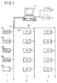
- the heterogeneous information centralization system of FIG. 1 consists of three networks 1, 2 and 3 of interactive terminals, which are connected to a central computer 4.
- the network 1 consists of a plurality of interactive terminals referenced 101, 102, 103, 104, 105, ... which are connected to the same communication bus 100, which bus is connected to the central computer 4 via a communication port of the computer.
- networks 2 and 3 are respectively constituted by interactive terminals referenced respectively 201, 202, 203, 204, 205, ... and 301, 302, 303, 304, 305, ... and connected respectively to communication bus 200 and 300.
- Terminal 101 is for example dedicated to access control, terminal 102 for staff pointing management, terminal 103 for workshop time management, terminal 104 for management of a photocopier, ...
- All of these Interactive kiosks have the common characteristic of being able to be used by an individual by means of an identification medium, such as a magnetic card on which is registered at least one identity number.
- All the terminals of the system also make it possible to acquire, at each use, a basic group of data, which is constituted by the identity read on the identification medium, the date and time of use, and additional data, the nature and number of which depend solely on the application to which the terminal is dedicated. For example, for a terminal dedicated to pointing, this additional data will be constituted by a code, entered by an individual using a keyboard and indicating either the start or the end of a work period.
- the centralization system of the invention allows the recovery by a single central computer 4, of all the heterogeneous information which is acquired by the interactive terminals in the form of elementary groups of data, for purposes of analysis and accounting management by said calculator.
- the central computer 4 was a microcomputer, and the communication buses 100, 200 and 300 were buses commonly called daisy chain, and made up of twisted pair pairs.
- Each network 1, 2 and 3 was of the RS 485 type, and constituted an asynchronous link between the central computer 4 and each interactive terminal. Data was exchanged between the central computer and each interactive terminal using a specific protocol commonly known as Modbus / Jbus.
- the microcomputer was connected to a printer 5 and to an encoder 6 allowing the edition of identification media.
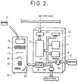
- All the interactive terminals of the centralization system of the invention comprise an electronic unit 7 whose internal architecture is shown in FIG. 2 and is advantageously identical for all the terminals, whatever the application to which they are dedicated.
- this identification medium was a magnetic card. It could also be an electronic badge, a bar code card, etc.
- the set 13 of peripherals may also include display means. 16, a keyboard 19, reading means 20, of the barcode reader type, as well as various sensors 17 or actuators 18, respectively allowing the input of information generated by a machine, or the control of this machine. This can for example be a photocopier, a beverage dispenser, or a machine mounted in line on a production line.
- the electronic unit 7 also includes storage means 21 of the random access memory type, accessible for writing and reading by the microprocessor 8 via the internal bus 10. These storage means 21 are also directly accessible for reading and writing, via a communication port 22, RS 485 type. All the electronic boxes 7 of the terminals of the system of FIG. 1 are connected to one of the communication buses 100, 200 or 300, depending on whether the interactive terminal is part of network 1, 2 or 3. The central computer 4 can thus asynchronously come read or write in the storage means 21, which act as a buffer memory between the microprocessor 8 and the central computer.
- the electronic unit 7 also includes a parallel input / output port 23, allowing in particular to connect the electronic unit 7 to a printer, a communication port 24, of V24 type, in particular allowing emulation of the electronic unit 7 by a videotex terminal, as well as a serial port, of RS 232 type, which makes it possible to communicate the microprocessor 8, according to the application to which the interactive terminal is dedicated with one or more peripherals, other than those of set 13.
- the power supply to the electronic unit 16 is provided by an energy box (sector / battery), which is not shown, and which makes it possible to make the interactive terminal autonomous in the event of a power cut, and more particularly to guarantee the operation of the terminal while preserving in particular the integrity of the information which is stored in the storage means 21.
- an energy box system / battery
- the storage means 21 allow the exchange of data between the microprocessor 8 and the central computer 4. Their structure depends solely on the application to which the terminal is dedicated.
- the memory zone 26 b comprises for each day of the week, and for each time slot of a given day, a group 27 of three parameters which respectively define the start time of the range, the end time and the level that is associated with the time slot.
- the parameter in zone 26 a corresponding to the operating mode can respectively take the values 0, 1, 2, 3, 4, 5, 6.
- the terminal When this parameter is 0, the terminal is configured in automatic mode, which means that its level of restriction depends on the time slot and the day of use of the terminal.
- this parameter has the value 1 to 6, the terminal is configured in manual mode, and the restriction level of this terminal is equal to the value of this parameter.
- the memory area 26c contains ten authorization parameters which make it possible to define the professional categories which are authorized to use the terminal.
- the memory area 26 d contains a red list containing a maximum of two hundred identity numbers, which are not authorized to use a terminal.
- the number of identity numbers in this list corresponds to the value of tenth parameter of memory area 26 a .
- the memory area 26 e is reserved for storing the elementary groups of data which must be acquired by the access control terminal.
- the terminal for access control can store up to six hundred elementary groups of data.
- Each elementary data group of a terminal dedicated to access control consists of an identity number which is read on the identification medium when the terminal is used, a date (day- month) and a timetable (hour-minute) for using the terminal.
- the remaining memory area 26 f is an area which is used only by the microprocessor 8. All the data contained in areas 26 a to 26 d , with the exception of the counter variable, are parameters which make it possible to configure the terminal of access control. These parameters are downloaded into the storage means 21 of a terminal dedicated to access control, by the central computer 4.
- the memory area 26 e is a buffer area between the microprocessor 8 and the central computer, which is write-accessible by the first and read by the second.
- step 30 the latter proceeds to a verification step 31 of the individual's right to use the terminal.
- This verification step is illustrated by the flow diagram of FIG. 4B, the different steps of which are sufficiently explicit for those skilled in the art and will therefore not be repeated in the present description.
- the microprocessor 8 performs step 32, depending on the peripherals it controls. This may for example involve controlling the timed opening of a door, then closing. If the microprocessor 8 detects an error in the application, for example a bad door opening or a non-crossing of the door, the microprocessor resumes the succession of steps which has just been described from step 29. If the application was carried out correctly, the microprocessor successively performs steps 33 to 38 which correspond to a writing in the memory area 26 e of the storage means 21, of an elementary group of data. Step 33 consists of a reading by the microprocessor of the counter variable, contained in the zone 26 a .
- This value allows the microprocessor 8 to calculate the address for writing the identity number, in step 34, in the memory area 26 e .
- the calculation of the writing address of the date step 35 and of the timetable step 36 in the area 26 e is carried out by successively incrementing the writing address of step 34.
- the microprocessor modifies the counter variable the value of the memory area 26a in the incrementing then resumes its background corresponding to steps 28 and 29.
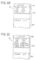
- FIGS. 3B and 3C show particular examples of structure 38 and 39 of the storage means 21 respectively of a terminal dedicated to pointing, and of a terminal dedicated to workshop time management.
- the memory areas 38 a and 38 b of the structures 38 and 39 are reserved for the storage of the counter variable.
- the memory areas 38 b and 39 b are reserved for storing elementary groups of data.
- the elementary group of data differs from the elementary group of a terminal dedicated to access control in that it includes additional data which is a code entered by the individual using the terminal using a keyboard, and indicating whether the individual begins or finishes his work.
- the elementary group of data differs from that of the pointing terminal in that it comprises two additional data which are constituted by the first and second parts of a number of business.
- the memory areas 38 c and 39 c are reserved only to the microprocessor 8.
- the score terminals and workshop time management do not realize, unlike dedicated terminals for access control, verification of right of use of the terminal by the individual. These terminals are only satisfied with acquiring, at each use, a basic group of data, in particular by managing a keyboard for entering the start or end code, and if it is a time management terminal workshop, for entering the business number in two parts.
- the invention is also not limited to access control, time attendance or workshop time management applications, but covers all of the company's applications that can be managed by means of a terminal.
- a terminal dedicated to machine management, such as a photocopier, drink dispenser, fuel pump ... and which allow on the one hand to control the right d use of the machine by an individual in the company, and on the other hand to count the quantities consumed by the individual.
- the software structure of the central computer 4 is organized into three levels.
- the first level contains the configuration of each network, 1, 2, 3 on which the various terminals of the system are installed, makes it possible to manage a database of company personnel, with a view to editing magnetic cards, and allows all the terminals dedicated to access control to be configured, by downloading the parameters into the storage means 21 of these terminals memory areas 26 a , 26 b , 26 c and 26 d .
- the configuration of the network is contained in a file, in which are specified for each terminal of the centralization system of FIG. 1 the address (or number) of the terminal on the network, and the application to which this terminal is dedicated.
- the network illustrated in Figure 1 we will find for example in this configuration file, the numbers (or addresses) of terminals 101, 102, 103 and 104, respectively associated with access control, pointing, workshop time management, and photocopier management.
- the number of these terminals is chosen so that it is characteristic of the network to which the terminal is connected.
- the computer is able to know the network, 1, 2 or 3 to which it is connected.
- the second level is broken down into as many separate modules as there are different applications. All these modules however have the same functionalities, among which the interrogation of all the terminals corresponding to the application of the module, with a view to recovering all the elementary groups which have been acquired by said terminals. Each module also knows the structure of the storage means 21 and the format of an elementary group of data which correspond to the application of the module.
- the third level also consists of one module per application, offering statistical and management functions (counting, averages, accumulation, ...) from the data that was collected at the second level.
- FIG. 5 shows the flow diagram making it possible to illustrate the main functionality of each module of the second level, which is the interrogation of the terminals dedicated to the application of the module.
- This interrogation is done in the following way.
- the user of the central computer 4 specifies at the first level the type of application for which he wishes to retrieve the information.
- the first level launches the module that corresponds to the application that has been specified by the user.
- the different steps implemented by this module are illustrated by the flowchart in Figure 5.
- the next step is to retrieve from the level 1 configuration file, the following terminal number, and the application with which it is associated.
- step 41 is repeated, until possibly finding a terminal number with which the application which has been specified by the user of the central computer 4 is associated.
- step 41 a terminal number associated with the application of the module is recovered, the central computer 4 performs step 42, which consists in recovering from the storage means 21 the terminal whose number has been found at the step 41, the value of the counter variable which is contained in the storage means 21. If this counter variable is zero, the central computer 4 deduces therefrom that no elementary group of data has been acquired by this terminal since the last interrogation, said terminal therefore not having been used. In this case, we pass to the next terminal number, repeating step 41.
- steps 43 to 47 are performed iteratively as many times as the value of this counter variable.
- Steps 43 to 46 correspond to the recovery in the storage means 21 of the terminal, of an elementary group of data.
- Step 47 corresponds to a saving in the file which was created or opened in step 40, of the elementary group of data which is recovered, associated with the number (or address) of the terminal which is interrogated. If the counter variable which was recovered in step 43 is equal to three, there are three elementary groups of data to be recovered in the storage means 21; steps 43 to 47 are therefore carried out three times.
- the latter resets the counter variable to zero in the storage means 21 of the terminal.
- the number of data which are recovered in step 47 depends on the format of the elementary groups which are acquired by the terminal and therefore on the application to which the thick headed.
- the read or write addresses in the storage means 21 of the terminal which are calculated in particular in steps 42, 43, 44, 45, 46 and 48 depend on the structure of these storage means which is known by the module corresponding to the application queried.
- Step 41 is carried out for all the terminals of the centralization system of the invention.
- the file from step 40 is closed (step 49).
- the interrogation requested by the user is finished.
- the file which was closed in step 49 contains all the elementary groups of data which have been recovered, associated with a terminal number.
Landscapes
- Physics & Mathematics (AREA)
- General Physics & Mathematics (AREA)
- Management, Administration, Business Operations System, And Electronic Commerce (AREA)
- Time Recorders, Dirve Recorders, Access Control (AREA)
- Storage Device Security (AREA)
- Financial Or Insurance-Related Operations Such As Payment And Settlement (AREA)
- Computer And Data Communications (AREA)
Claims (9)
- System zur Zentralisierung von heterogenen Informationen, die mit einer Identität zusammenhängen und von verteilten Anschlüssen gesammelt und zeitlich gekennzeichnet werden, mit mehreren interaktiven autonomen Anschlüssen (101, ... 201, ... 301, ...) zur Verwendung in Zusammenhang mit einem Identifikationsträger (15) und in einem Netz mit einem Zentralrechner (4) eingebunden, wobei jeder Anschluß Speichervorrichtungen (21) und Bearbeitungsvorrichtungen (8, 9, 11) umfaßt, die einerseits in Abhängigkeit von der Anwendung, für welche der Anschluß ausgelegt ist, zum Verwalten einer oder mehrerer Peripherievorrichtungen (13) geeignet sind, wobei diese wenigstens Lesevorrichtungen (14) für den Identifikationsträger (15) umfassen, und die andererseits geeignet sind, bei jeder Benutzung des Anschlusses in den Speichervorrichtungen (21) eine elementare Datengruppe aus wenigstens der in dem Identifikationsträger eingeschriebenen Identität, dem Datum und der Zeit der Verwendung des Anschlusses zu speichern,
dadurch gekennzeichnet, daß
die Speichervorrichtungen (21) jedes Anschlusses zum Lesen und unter Umständen zum Schreiben durch den Zentralrechner (4) zugänglich sind, daß für jeden Anschluß die Struktur der Speichervorrichtungen (21) und das Format der elementaren Datengruppen nur von der Anwendung abhängen, für die der Anschluß gedacht ist, und daß der Zentralrechner (4) die Struktur der Speichervorrichtungen (21) und das Format einer elementaren Datengruppe für jeden Anwendungstyp kennt, wie auch die Adresse und den Anwendungstyp jedes einzelnen der Anschlüsse, die mit ihm verbunden sind, und er geeignet ist, die Speichervorrichtungen (21) eines Anschlusses zu adressieren, der ausgewählt wurde, um in den Speichervorrichtungen (21) des besagten Anschlusses alle elementaren Datengruppen auszulesen, die seit der letzten Abfrage des Anschlusses abgespeichert worden sind. - System nach Anspruch 1,
dadurch gekennzeichnet, daß
die Speichervorrichtungen (21) jedes Anschlusses eine Zählvariable beinhalten, die durch die Bearbeitungsvorrichtungen (8, 9, 11) bei jeder Benutzung des Anschlusses inkrementiert wird und die durch den Zentralrechner (4) vor jeder Ausleseoperation von elementaren Datengruppen, die in dem Anschluß gespeichert sind, gelesen wird und die auf Null zurückgesetzt wird durch den Zentralrechner, wenn diese Operation einmal beendet ist. - System nach Anspruch 2,
dadurch gekennzeichnet, daß
die Zählvariable von den Bearbeitungsvorrichtungen (8, 9, 11) zur Berechnung der Schreibadressen für Daten jeder elementaren Gruppe in den Speichervorrichtungen (21) verwendet wird. - System nach einem der Ansprüche 1 bis 3,
dadurch gekennzeichnet, daß
für wenigstens einen der Anschlüsse die Verwaltung der Peripherievorrichtungen durch die Bearbeitungsvorrichtungen von Parametern abhängt, die in den Speichervorrichtungen (21) abgespeichert sind, und daß der Zentralrechner (4) zum Modifizieren des Wertes dieser Parameter geeignet ist. - System nach Anspruch 4,
dadurch gekennzeichnet, daß
für wenigstens einen der Anschlüsse, eventuell Vorrichtungen für die manuelle Erfassung umfassend, die Bearbeitungsvorrichtungen (8, 9, 11) dazu geeignet sind, die Benutzung des Anschlusses freizugeben oder zu verweigern, nachdem alle oder ein Teil der auf dem Identifikationsträger (15) eingeschriebenen Informationen und/oder eventuell alle oder ein Teil der erfaßten Daten mit einem oder mehreren speziellen Parametern, die Freigabeparameter genannt werden, verglichen worden sind. - System nach Anspruch 4,
dadurch gekennzeichnet, daß
auf dem Identifikationsträger ein Ablaufdatum eingeschrieben ist, und daß die Bearbeitungsvorrichtungen wenigstens eines Anschlusses dazu geeignet sind, die Benutzung des Anschlusses freizugeben oder zu verweigern, nachdem das Ablaufdatum mit dem Benutzungsdatum des Anschlusses verglichen worden ist. - System nach Anspruch 4,
dadurch gekennzeichnet, daß
in dem Identifikationsträger ein Geheimcode eingeschrieben ist, und daß für wenigstens einen der Anschlüsse, Vorrichtungen zur manuellen Erfassung (19) umfassend, die Bearbeitungsvorrichtungen geeignet sind, die Benutzung des Anschlusses freizugeben oder zu verweigern, nachdem der Geheimcode mit dem Code, der mit Vorrichtungen für die manuelle Erfassung eingegeben wurde, verglichen worden ist. - System nach den Ansprüchen 5, 6 und 7,
dadurch gekennzeichnet, daß
die Speichervorrichtungen (21) wenigstens eines Anschlusses (101), die ausgelegt sind für die Steuerung des Zugriffs, wenigstens einen Parameter enthalten, der Restriktionspegel genannt wird, und daß die Eignung der Bearbeitungsvorrichtungen zum Freigeben oder Verweigern der Benutzung des Anschlusses (101) vom Wert dieses Parameters abhängen. - System nach Anspruch 8,
dadurch gekennzeichnet, daß
die Speichervorrichtungen (21) der Anschlüsse (101), die für die Steuerung des Zugriffs ausgelegt sind, mehrere Restriktionspegelparameter enthalten, die jeweils mit einem Zeitbereich und eventuell einem Wochentag assoziiert sind, und daß die Bearbeitungsvorrichtungen (8, 9, 11) geeignet sind, den Restriktionspegelparameter gemäß Zeitbereich und eventuell Benutzungsdatum des Anschlusses auszulesen.
Applications Claiming Priority (2)
| Application Number | Priority Date | Filing Date | Title |
|---|---|---|---|
| FR9304867 | 1993-04-20 | ||
| FR9304867A FR2704335B1 (fr) | 1993-04-20 | 1993-04-20 | Système de centralisation d'informations hétérogènes, liées à une identité, collectées et horodatées, à partir de bornes délocalisées. |
Publications (2)
| Publication Number | Publication Date |
|---|---|
| EP0621565A1 EP0621565A1 (de) | 1994-10-26 |
| EP0621565B1 true EP0621565B1 (de) | 1997-07-16 |
Family
ID=9446416
Family Applications (1)
| Application Number | Title | Priority Date | Filing Date |
|---|---|---|---|
| EP94490017A Expired - Lifetime EP0621565B1 (de) | 1993-04-20 | 1994-04-18 | System zur Zentralisierung von verschiedenartigen Informationen, die mit einer Identität verbunden sind und an örtlich verbreiteten Pfosten gesammelt und zeitgestempelt werden |
Country Status (5)
| Country | Link |
|---|---|
| EP (1) | EP0621565B1 (de) |
| AT (1) | ATE155597T1 (de) |
| DE (1) | DE69404207T2 (de) |
| ES (1) | ES2106483T3 (de) |
| FR (1) | FR2704335B1 (de) |
Families Citing this family (7)
| Publication number | Priority date | Publication date | Assignee | Title |
|---|---|---|---|---|
| ES2114488B1 (es) * | 1996-04-18 | 1999-01-01 | Univ Madrid Politecnica | Sistema de seguridad para acceso, identificacion y control de presencia en viviendas, locales, y superficies comerciales, que puede realizar transacciones electronicas mediante tarjeta inteligente. |
| FR2751814B1 (fr) | 1996-07-24 | 1998-09-25 | Gemplus Card Int | Systeme de controle et de gestion de services |
| GB2363237A (en) * | 2000-06-10 | 2001-12-12 | Secr Defence | Integrated security system |
| GB0026642D0 (en) * | 2000-11-01 | 2000-12-13 | Datascope Plc | Method and apparatus for remotely monitoring the time and attendance of workers |
| US6992564B2 (en) | 2001-07-19 | 2006-01-31 | Symbol Technologies, Inc. | Cordless identification security system and method |
| FR2830663B1 (fr) * | 2001-10-08 | 2005-08-05 | France Telecom | Procede et systeme de gestion d'evenement |
| US20050267964A1 (en) * | 2004-04-28 | 2005-12-01 | Guenter Kech | Method for providing apparatus specific information and corresponding system |
Family Cites Families (7)
| Publication number | Priority date | Publication date | Assignee | Title |
|---|---|---|---|---|
| AU4767479A (en) * | 1978-06-19 | 1980-01-03 | Am International Inc. | Copier control and record keeping |
| US4408291A (en) * | 1979-06-15 | 1983-10-04 | M. Wile & Company, Inc. | Point-of-manufacture data acquisition system |
| US4847791A (en) * | 1982-08-16 | 1989-07-11 | Martin Joseph H | Timekeeping system |
| FR2584557B1 (fr) * | 1985-07-02 | 1989-07-28 | Smh Alcatel | Systeme de telecontrole pour machines a affranchir |
| FR2635895A1 (fr) * | 1988-08-26 | 1990-03-02 | Unidel Securite | Systeme de gestion d'acces pour cartes a microcalculateur incorpore et procede s'y rapportant |
| GB2230115A (en) * | 1989-04-05 | 1990-10-10 | Wang Kenneth Kuk Kei | Data collection and processing |
| US5084875A (en) * | 1989-12-13 | 1992-01-28 | Joseph Weinberger | System for automatically monitoring copiers from a remote location |
-
1993
- 1993-04-20 FR FR9304867A patent/FR2704335B1/fr not_active Expired - Fee Related
-
1994
- 1994-04-18 ES ES94490017T patent/ES2106483T3/es not_active Expired - Lifetime
- 1994-04-18 EP EP94490017A patent/EP0621565B1/de not_active Expired - Lifetime
- 1994-04-18 AT AT94490017T patent/ATE155597T1/de not_active IP Right Cessation
- 1994-04-18 DE DE69404207T patent/DE69404207T2/de not_active Expired - Fee Related
Also Published As
| Publication number | Publication date |
|---|---|
| EP0621565A1 (de) | 1994-10-26 |
| DE69404207T2 (de) | 1997-12-11 |
| ATE155597T1 (de) | 1997-08-15 |
| DE69404207D1 (de) | 1997-08-21 |
| ES2106483T3 (es) | 1997-11-01 |
| FR2704335B1 (fr) | 1995-07-13 |
| FR2704335A1 (fr) | 1994-10-28 |
Similar Documents
| Publication | Publication Date | Title |
|---|---|---|
| CA2007335C (fr) | Systeme de paiement electronique de transports et de services publics par cartes a microcircuits | |
| EP1330805A1 (de) | Verfahren und vorrichtung zur parkplatzreservierung | |
| WO1995022125A1 (fr) | Procede et systeme de transaction par carte a puce | |
| EP0270435A1 (de) | Einrichtung für die Überwachung der Besucherzahl einer Ausstellung, Messe oder dergleichen | |
| WO2008065265A2 (fr) | Procede et dispositif de personnalisation d'une entite electronique portable | |
| CA2261830A1 (fr) | Systeme de controle et de gestion de services | |
| EP0621565B1 (de) | System zur Zentralisierung von verschiedenartigen Informationen, die mit einer Identität verbunden sind und an örtlich verbreiteten Pfosten gesammelt und zeitgestempelt werden | |
| WO2002035464A2 (fr) | Systeme d'identification electronique sans contact | |
| FR2644605A1 (fr) | Systeme de releve de compteurs | |
| FR2637710A1 (fr) | Procede et dispositif de commande electronique multifonction a haute securite comportant une carte a puce | |
| EP0271624B1 (de) | Verfahren zur Ausstellung einer Rechnung von verschiedenen Produkten | |
| EP0495741B1 (de) | System zur Verbuchung von Verbrauchseinheiten, mit optimierter Verwaltung, besonders zur Verbuchung von Zeiteinheiten beim Parken | |
| EP1256915B1 (de) | Automatisiertes System und Verfahren zur Herstellung und Verteilung von Kassenbeständen | |
| EP0909432A1 (de) | Tragbares gerät zur durchführung gesicherter interner transaktionen und transaktionen mit chipkarten, und verfahren dazu | |
| EP1064596A1 (de) | Verfahren und system zum elektronischen sammeln von geld | |
| WO2004056071A1 (fr) | Procede de communication entre serveurs avec conversion de format des donnees et dispositif pour sa mise en oeuvre | |
| WO2004036511A2 (fr) | Systeme de carte a puces securise utilisable comme porte-monnaie electronique | |
| EP0956540A1 (de) | Gesichertes zugangskontrollsystem zur automatischen ungültigkeitserklärung von gestohlenen oder verlorenen elektronischen schlüsseln | |
| EP4187468A1 (de) | Verwaltung einer elektronischen geldbörse in verbindung mit einer gemeinsamen verbundenen vorrichtung | |
| BE1018670A3 (fr) | Systeme et procede de fidelisation. | |
| FR2725813A3 (fr) | Procede d'exploitation d'un support de donnees, objet portable et systeme de gestion mettant en oeuvre le procede d'exploitation | |
| EP1713041A1 (de) | Zahlungssystem mit Bankkarte | |
| WO2007125212A2 (fr) | Procede et dispositif de personnalisation d'une entite electronique portable | |
| EP1156620A1 (de) | Verbesserte Vorrichtung zur Datenaustausch in einem Netzwerk, und zugehörige Zahlungskarte und zugehöriges Verfahren | |
| WO1992020031A1 (fr) | Dispositif de gestion et de facturation |
Legal Events
| Date | Code | Title | Description |
|---|---|---|---|
| PUAI | Public reference made under article 153(3) epc to a published international application that has entered the european phase |
Free format text: ORIGINAL CODE: 0009012 |
|
| AK | Designated contracting states |
Kind code of ref document: A1 Designated state(s): AT BE CH DE DK ES GB GR IE IT LI LU NL PT SE |
|
| 17P | Request for examination filed |
Effective date: 19940927 |
|
| GRAG | Despatch of communication of intention to grant |
Free format text: ORIGINAL CODE: EPIDOS AGRA |
|
| GRAH | Despatch of communication of intention to grant a patent |
Free format text: ORIGINAL CODE: EPIDOS IGRA |
|
| 17Q | First examination report despatched |
Effective date: 19960719 |
|
| GRAH | Despatch of communication of intention to grant a patent |
Free format text: ORIGINAL CODE: EPIDOS IGRA |
|
| GRAA | (expected) grant |
Free format text: ORIGINAL CODE: 0009210 |
|
| AK | Designated contracting states |
Kind code of ref document: B1 Designated state(s): AT BE CH DE DK ES GB GR IE IT LI LU NL PT SE |
|
| PG25 | Lapsed in a contracting state [announced via postgrant information from national office to epo] |
Ref country code: GR Free format text: LAPSE BECAUSE OF FAILURE TO SUBMIT A TRANSLATION OF THE DESCRIPTION OR TO PAY THE FEE WITHIN THE PRESCRIBED TIME-LIMIT Effective date: 19970716 Ref country code: DK Effective date: 19970716 Ref country code: AT Effective date: 19970716 |
|
| REF | Corresponds to: |
Ref document number: 155597 Country of ref document: AT Date of ref document: 19970815 Kind code of ref document: T |
|
| REG | Reference to a national code |
Ref country code: CH Ref legal event code: EP |
|
| GBT | Gb: translation of ep patent filed (gb section 77(6)(a)/1977) |
Effective date: 19970716 |
|
| REF | Corresponds to: |
Ref document number: 69404207 Country of ref document: DE Date of ref document: 19970821 |
|
| ITF | It: translation for a ep patent filed | ||
| PG25 | Lapsed in a contracting state [announced via postgrant information from national office to epo] |
Ref country code: SE Effective date: 19971016 |
|
| PG25 | Lapsed in a contracting state [announced via postgrant information from national office to epo] |
Ref country code: PT Effective date: 19971022 |
|
| REG | Reference to a national code |
Ref country code: ES Ref legal event code: FG2A Ref document number: 2106483 Country of ref document: ES Kind code of ref document: T3 |
|
| PG25 | Lapsed in a contracting state [announced via postgrant information from national office to epo] |
Ref country code: IE Free format text: LAPSE BECAUSE OF NON-PAYMENT OF DUE FEES Effective date: 19980330 |
|
| REG | Reference to a national code |
Ref country code: IE Ref legal event code: FD4D Ref document number: 75120 Country of ref document: IE |
|
| PG25 | Lapsed in a contracting state [announced via postgrant information from national office to epo] |
Ref country code: LU Free format text: LAPSE BECAUSE OF NON-PAYMENT OF DUE FEES Effective date: 19980418 |
|
| PG25 | Lapsed in a contracting state [announced via postgrant information from national office to epo] |
Ref country code: LI Free format text: LAPSE BECAUSE OF NON-PAYMENT OF DUE FEES Effective date: 19980430 Ref country code: CH Free format text: LAPSE BECAUSE OF NON-PAYMENT OF DUE FEES Effective date: 19980430 |
|
| PLBE | No opposition filed within time limit |
Free format text: ORIGINAL CODE: 0009261 |
|
| STAA | Information on the status of an ep patent application or granted ep patent |
Free format text: STATUS: NO OPPOSITION FILED WITHIN TIME LIMIT |
|
| 26N | No opposition filed | ||
| REG | Reference to a national code |
Ref country code: CH Ref legal event code: PL |
|
| PGFP | Annual fee paid to national office [announced via postgrant information from national office to epo] |
Ref country code: NL Payment date: 19990322 Year of fee payment: 6 |
|
| PGFP | Annual fee paid to national office [announced via postgrant information from national office to epo] |
Ref country code: GB Payment date: 19990413 Year of fee payment: 6 |
|
| PGFP | Annual fee paid to national office [announced via postgrant information from national office to epo] |
Ref country code: ES Payment date: 19990416 Year of fee payment: 6 Ref country code: DE Payment date: 19990416 Year of fee payment: 6 |
|
| PGFP | Annual fee paid to national office [announced via postgrant information from national office to epo] |
Ref country code: BE Payment date: 19990517 Year of fee payment: 6 |
|
| PG25 | Lapsed in a contracting state [announced via postgrant information from national office to epo] |
Ref country code: GB Free format text: LAPSE BECAUSE OF NON-PAYMENT OF DUE FEES Effective date: 20000418 |
|
| PG25 | Lapsed in a contracting state [announced via postgrant information from national office to epo] |
Ref country code: ES Free format text: THE PATENT HAS BEEN ANNULLED BY A DECISION OF A NATIONAL AUTHORITY Effective date: 20000419 |
|
| PG25 | Lapsed in a contracting state [announced via postgrant information from national office to epo] |
Ref country code: BE Free format text: LAPSE BECAUSE OF NON-PAYMENT OF DUE FEES Effective date: 20000430 |
|
| BERE | Be: lapsed |
Owner name: SOC. FH2I S.A. Effective date: 20000430 |
|
| PG25 | Lapsed in a contracting state [announced via postgrant information from national office to epo] |
Ref country code: NL Free format text: LAPSE BECAUSE OF NON-PAYMENT OF DUE FEES Effective date: 20001101 |
|
| GBPC | Gb: european patent ceased through non-payment of renewal fee |
Effective date: 20000418 |
|
| NLV4 | Nl: lapsed or anulled due to non-payment of the annual fee |
Effective date: 20001101 |
|
| PG25 | Lapsed in a contracting state [announced via postgrant information from national office to epo] |
Ref country code: DE Free format text: LAPSE BECAUSE OF NON-PAYMENT OF DUE FEES Effective date: 20010201 |
|
| REG | Reference to a national code |
Ref country code: ES Ref legal event code: FD2A Effective date: 20020304 |
|
| PG25 | Lapsed in a contracting state [announced via postgrant information from national office to epo] |
Ref country code: IT Free format text: LAPSE BECAUSE OF NON-PAYMENT OF DUE FEES;WARNING: LAPSES OF ITALIAN PATENTS WITH EFFECTIVE DATE BEFORE 2007 MAY HAVE OCCURRED AT ANY TIME BEFORE 2007. THE CORRECT EFFECTIVE DATE MAY BE DIFFERENT FROM THE ONE RECORDED. Effective date: 20050418 |