EP0621741A2 - Betriebsgerät für elektrische Lampen - Google Patents
Betriebsgerät für elektrische Lampen Download PDFInfo
- Publication number
- EP0621741A2 EP0621741A2 EP94105614A EP94105614A EP0621741A2 EP 0621741 A2 EP0621741 A2 EP 0621741A2 EP 94105614 A EP94105614 A EP 94105614A EP 94105614 A EP94105614 A EP 94105614A EP 0621741 A2 EP0621741 A2 EP 0621741A2
- Authority
- EP
- European Patent Office
- Prior art keywords
- bracket
- base part
- operating device
- cables
- recesses
- Prior art date
- Legal status (The legal status is an assumption and is not a legal conclusion. Google has not performed a legal analysis and makes no representation as to the accuracy of the status listed.)
- Granted
Links
- 230000002441 reversible effect Effects 0.000 abstract 1
- 229910052736 halogen Inorganic materials 0.000 description 1
- 150000002367 halogens Chemical class 0.000 description 1
Images

Classifications
-
- H—ELECTRICITY
- H05—ELECTRIC TECHNIQUES NOT OTHERWISE PROVIDED FOR
- H05B—ELECTRIC HEATING; ELECTRIC LIGHT SOURCES NOT OTHERWISE PROVIDED FOR; CIRCUIT ARRANGEMENTS FOR ELECTRIC LIGHT SOURCES, IN GENERAL
- H05B41/00—Circuit arrangements or apparatus for igniting or operating discharge lamps
- H05B41/02—Details
-
- H—ELECTRICITY
- H01—ELECTRIC ELEMENTS
- H01R—ELECTRICALLY-CONDUCTIVE CONNECTIONS; STRUCTURAL ASSOCIATIONS OF A PLURALITY OF MUTUALLY-INSULATED ELECTRICAL CONNECTING ELEMENTS; COUPLING DEVICES; CURRENT COLLECTORS
- H01R13/00—Details of coupling devices of the kinds covered by groups H01R12/70 or H01R24/00 - H01R33/00
- H01R13/58—Means for relieving strain on wire connection, e.g. cord grip, for avoiding loosening of connections between wires and terminals within a coupling device terminating a cable
- H01R13/595—Bolts operating in a direction transverse to the cable or wire
-
- H—ELECTRICITY
- H05—ELECTRIC TECHNIQUES NOT OTHERWISE PROVIDED FOR
- H05B—ELECTRIC HEATING; ELECTRIC LIGHT SOURCES NOT OTHERWISE PROVIDED FOR; CIRCUIT ARRANGEMENTS FOR ELECTRIC LIGHT SOURCES, IN GENERAL
- H05B39/00—Circuit arrangements or apparatus for operating incandescent light sources
-
- H—ELECTRICITY
- H01—ELECTRIC ELEMENTS
- H01R—ELECTRICALLY-CONDUCTIVE CONNECTIONS; STRUCTURAL ASSOCIATIONS OF A PLURALITY OF MUTUALLY-INSULATED ELECTRICAL CONNECTING ELEMENTS; COUPLING DEVICES; CURRENT COLLECTORS
- H01R33/00—Coupling devices specially adapted for supporting apparatus and having one part acting as a holder providing support and electrical connection via a counterpart which is structurally associated with the apparatus, e.g. lamp holders; Separate parts thereof
- H01R33/05—Two-pole devices
- H01R33/06—Two-pole devices with two current-carrying pins, blades or analogous contacts, having their axes parallel to each other
- H01R33/08—Two-pole devices with two current-carrying pins, blades or analogous contacts, having their axes parallel to each other for supporting tubular fluorescent lamp
Definitions
- the invention relates to an operating device for electric lamps according to the preamble of protection claim 1.
- Operating devices of this type are required in particular for the operation of fluorescent lamps and low-voltage halogen incandescent lamps. They consist of an electrical circuit arrangement that is matched to the electrical properties of the lamps to be operated, a housing that encloses the circuit arrangement, and a lamp-side connection part that serves to connect the lamps to the operating device, and a network-side connection part, via which the operating device connects to a electrical voltage source is connected.
- the connecting parts of common operating devices are usually equipped with a strain relief device for two connecting cables.
- a disadvantage of these operating devices is that the strain relief devices of their connecting parts are only suitable for a certain type of cable.
- the network-side connection part of the operating device according to the invention is equipped with a two-part strain relief device. It consists of a base part and a bracket that can be screwed to it, between which the connecting cables are clamped.
- the bracket is provided with two differently structured surfaces, each having two recesses, which can optionally interact with a surface of the base part which also has recesses in order to fix the connecting cable in a clamped manner.
- the depressions in the surfaces of the bracket and the base part form bushings for the connection cable.
- the operating device consists of a plastic housing 1, an electrical circuit which is accommodated in the interior of the housing 1, a mains-side connection part 7 for connecting the operating device to an electrical voltage source and a lamp-side connection part 8 for connecting one or more electrical lamps to the operating device .
- the network-side connection part 7 has a strain relief device 2, 3 with two bushings for a connecting cable 4 and 5, respectively.
- This strain relief device consists of a base part 2 made in one piece with the housing 1 and a bracket 3 which is screwed to the base part 2 by means of a screw 6 is.
- the surface 20 of the base part 2 facing the bracket 3 is provided with two similar recesses 20a, 20b lying in one plane.
- the bracket 3 has two differently structured surfaces 30, 31, both of which are each equipped with two identical depressions 30a, 30b and 31a, 31b.
- the depressions 30a, 30b in the surface 30 likewise lie in one plane, while the depressions 31a, 31b in the surface 31 of the bracket 3 are arranged in different planes running parallel to one another, which is achieved by a step-like surface 31.
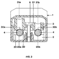
- FIG. 2 shows the mounting of the bracket 3 for two identical connecting cables 4.
- the bracket 3 is mounted here that the surface 30 forms the underside of the bracket 3 and cooperates with the surface 20 of the base part 2 to fix the connecting cable 4.
- the depressions 20a and 30a and 20b and 30b each form a passage for one of the two connecting cables 4.
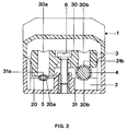
- Figure 3 shows the mounting of the bracket 3 for two different connecting cables 4, 5.
- the bracket 3 is mounted here so that its surface 31 forms the underside of the bracket 3 and interacts with the surface 20 of the base part 2 to the connecting cables 4, 5th to fix.
- the depressions 20a, 31a here form a bushing for the connecting cable 5, which is oval in cross section, while the depressions 20b, 31b form a bushing for the connecting cable 4, which is circular in cross section.
- bracket 3 rests with its surface 31 on the surface 20 of the base part 2 and the surface 31 acts as a support on the side which is provided with the depression 31a.
Landscapes
- Non-Portable Lighting Devices Or Systems Thereof (AREA)
- Details Of Connecting Devices For Male And Female Coupling (AREA)
- Circuit Arrangement For Electric Light Sources In General (AREA)
- Circuit Arrangements For Discharge Lamps (AREA)
Abstract
Description
- Die Erfindung betrifft ein Betriebsgerät für elektrische Lampen gemaß dem Obergriff des Schutzanspruchs 1.
- Derartige Betriebsgeräte werden insbesondere zum Betrieb von Leuchtstofflampen und Niedervolthalogenglühlampen benötigt.
Sie bestehen aus einer auf die elektrischen Eigenschaften der zu betreibenden Lampen abgestimmten elektrischen Schaltungsanordnung, einem Gehäuse, das die Schaltungsanordnung umschließt, und einem lampenseitigen Anschlußteil, das zum Anschluß der Lampen an das Betriebsgerät dient, sowie einem netzseitigen Anschlußteil, über das das Betriebsgerät mit einer elektrischen Spannungsquelle verbunden ist. - Die Anschlußteile gebräuchlicher Betriebsgeräte sind üblicherweise mit einer Zugentlastungsvorrichtung für jeweils zwei Anschlußkabel ausgerüstet. Ein Nachteil dieser Betriebsgeräte besteht darin, daß die Zugentlastungsvorrichtungen ihrer Anschlußteile nur für einen bestimmten Kabeltyp geeignet sind.
- Es ist die Aufgabe der Erfindung, ein Betriebsgerät für elektrische Lampen bereitzustellen, bei dem zumindest das netzseitige Anschlußteil eine Zugentlastungsvorrichtung besitzt, die für unterschiedliche Anschlußkabel geeignet ist.
- Diese Aufgabe wird erfindungsgemäß durch die kennzeichnenden Merkmale des Schutzanspruchs 1 gelöst. Besonders vorteilhafte Ausführungen der Erfindung sind in den Unteransprüchen beschrieben.
- Das netzseitige Anschlußteil des erfindungsgemäßen Betriebsgerätes ist mit einer zweiteiligen Zugentlastungsvorrichtung ausgestattet. Sie besteht aus einem Basisteil und einem mit diesem verschraubbaren Bügel, zwischen denen die Anschlußkabel eingeklemmt werden. Der Bügel ist mit zwei unterschiedlich strukturierten, jeweils zwei Vertiefungen aufweisenden Oberflächen versehen, die wahlweise mit einer ebenfalls Vertiefungen besitzenden Oberfläche des Basisteils zusammenwirken können, um die Anschlußkabel klemmend zu fixiern. Die Vertiefungen in den Oberflächen des Bügels und des Basisteils bilden dabei Durchführungen für die Anschlußkabel. Durch Wenden des Bügels ist es möglich, zwei Anschlußkabel gleichen oder unterschiedlichen Querschnitts in die Zugentlastungsvorrichtung einzuspannen. Diese Zugentlastungsvorrichtung erlaubt es, alle gängigen Kabeltypen zu entlasten. Ferner ist es möglich, auch nur ein einziges Kabel in dieser Vorrichtung zu montieren, ohne daß der Bügel verkantet, was eine Deformation des Gehäuses zur Folge hätte.
- Die Erfindung wird nachstehend anhand eines bevorzugten Ausführungsbeispiels näher erläutert. Es zeigen:
- Figur 1
- eine Seitenansicht eines erfindungsgemäßen Betriebsgerätes
- Figur 2
- einen Querschnitt durch das Betriebsgerät entlang der Schnittlinie A-A gemäß Fig. 1, für zwei identische Anschlußkabel
- Figur 3
- einen Querschnitt durch das Betriebsgerät entlang der Schnittlinie A-A gemäß Fig. 1, für zwei unterschiedliche Anschlußkabel
- Das erfindungsgemäße Betriebsgerät besteht aus einem Kunststoffgehäuse 1, einer elektrischen Schaltung, die im Innenraum des Gehäuses 1 untergebracht ist, einem netzseitigen Anschlußteil 7 zum Anschluß des Betriebsgerätes an eine elektrische Spannungsquelle und aus einem lampenseitigen Anschlußteil 8 zum Anschluß einer oder mehrerer elektrischer Lampen an das Betriebsgerät.
- Das netzseitige Anschlußteil 7 besitzt eine Zugentlastungsvorrichtung 2, 3 mit zwei Durchführungen für je ein Anschlußkabel 4 bzw. 5. Diese Zugentlastungsvorrichtung besteht aus einem einteilig mit dem Gehäuse 1 ausgeführten Basisteil 2 und einem Bügel 3, der mittels einer Schraube 6 mit dem Basisteil 2 verschraubt ist. Die dem Bügel 3 zugewandte Oberfläche 20 des Basisteils 2 ist mit zwei in einer Ebene liegenden, gleichartigen Vertiefungen 20a, 20b versehen sind.
- Der Bügel 3 besitzt zwei unterschiedlich strukturierte Oberflächen 30, 31, die beide jeweils mit zwei gleichartigen Vertiefungen 30a, 30b bzw. 31a, 31b ausgestattet sind. Die Vertiefungen 30a, 30b in der Oberfläche 30 liegen ebenfalls in einer Ebene, während die Vertiefungen 31a, 31b in der Oberfläche 31 des Bügels 3 in verschiedenen, parallel zueinander verlaufenden Ebenen angeordnet sind, was durch eine stufenartig ausgebildete Oberfläche 31 erreicht wird.
- Figur 2 zeigt die Montage des Bügels 3 für zwei identische Anschlußkabel 4. Der Bügel 3 ist hier so montiert, daß die Oberfläche 30 die Unterseite des Bügels 3 bildet und mit der Oberfläche 20 des Basisteils 2 zusammenwirkt, um die Anschlußkabel 4 zu fixieren. Die Vertiefungen 20a und 30a sowie 20b und 30b bilden jeweils eine Durchführung für eines der beiden Anschlußkabel 4. Durch Anziehen der Schraube 6 werden die beiden identischen Anschlußkabel 4 zwischen den Oberflächen 20, 30 des Basisteils 2 und des Bügels 3 eingeklemmt.
- Figur 3 zeigt die Montage des Bügels 3 für zwei unterschiedliche Anschlußkabel 4, 5. Der Bügel 3 ist hier so montiert, daß seine Oberfläche 31 die Unterseite des Bügels 3 bildet und mit der Oberfläche 20 des Basisteils 2 zusammenwirkt, um die Anschlußkabel 4, 5 zu fixieren. Die Vertiefungen 20a, 31a bilden hier eine Durchführung für das im Querschnitt ovale Anschlußkabel 5, während die Vertiefungen 20b, 31b eine Durchführung für das im Querschnitt kreisförmige Anschlußkabel 4 formen. Durch Anziehen der Schraube 6 werden die beiden unterschiedlichen Anschlußkabel 4, 5 zwischen den Oberflächen 20, 31 des Basisteils 2 und des Bügels 3 festgeklemmt.
- Es ist auch möglich, nur ein Anschlußkabel 4 bzw. 5 zu montieren. Dann liegt der Bügel 3 mit seiner Oberfläche 31 auf der Oberfläche 20 des Basisteils 2 auf und die Oberfläche 31 wirkt auf derjenigen Seite, die mit der Vertiefung 31a versehen ist, als Auflager.
Claims (4)
- Betriebsgerät für elektrische Lampen, bestehend aus einem Gehäuse (1), einer elektrischen Schaltung, die im Innenraum des Gehäuses (1) angeordnet ist, einem lampenseitigen Anschlußteil (8) zum Anschluß mindestens einer elektrischen Lampe an das Betriebsgerät und einem netzseitigen Anschlußteil (7) zum Anschluß des Betriebsgerätes an eine elektrische Spannungsquelle, wobei- zumindest das netzseitige Anschlußteil (7) eine Zugentlastungsvorrichtung (2, 3) mit zwei Durchführungen besitzt,- das netzseitige Anschlußteil (7) mindestens ein Anschlußkabel (4) bzw. (5) besitzt, das durch eine der beiden Durchführungen hindurchgeführt ist,- die Zugentlastungsvorrichtung (2, 3) aus einem starr mit dem Gehäuse (1) verbundenen Basisteil (2) und einem Bügel (3) besteht,- das Basisteil (2) und der Bügel (3) zusammenwirkende, mit Vertiefungen (20a, 20b; 30a, 30b) versehene Oberflächen (20; 30) besitzen, zwischen denen die bzw. das Anschlußkabel (4) eingeklemmt sind bzw. ist,- die Durchführungen jeweils von einer Vertiefung (20a, 30a; 20b, 30b) in den zusammenwirkenden Oberflächen (20; 30) des Basisteils (2) und des Bügels (3) gebildet werden,dadurch gekennzeichnet, daß der Bügel (3) mindestens zwei mit Vertiefungen (30a, 30b; 31a, 31b) versehene, unterschiedlich strukturierte Oberflächen (30; 31) besitzt, so daß die mit den Vertiefungen (20a, 20b) versehene Oberfläche (20) des Basisteils (2) wahlweise mit einer dieser Oberflächen (30; 31) des Bügels (3) zusammenwirken kann, abhängig von der Form, den Querabmessungen und der Anzahl der durchgeführten Anschlußkabel (4, 5) bzw. des durchgeführten Anschlußkabels, so daß die Oberfläche (31) mit der Vertiefung (31a) als Auflager wirken kann.
- Betriebsgerät für elektrische Lampen nach Anspruch 1, dadurch gekennzeichnet, daß die Vertiefungen (20a, 20b) in der Oberfläche (20) des Basisteils (2) in einer Ebene angeordnet sind und die erste Oberfläche (30) des Bügels (3), die mit zwei in einer Ebene liegenden Vertiefungen (30a, 30b) versehen ist, mit der Oberfläche (20) des Basisteils (2) zusammenwirkt, so daß die Vertiefungen (20a, 30a; 20b, 30b) zwei gleich große Durchführungen für die Anschlußkabel (4, 5) bilden und die Anschlußkabel (4, 5) zwischen der ersten Oberfläche (30) des Bügels (3) und der Oberfläche (20) des Basisteils (2) eingeklemmt werden.
- Betriebsgerät für elektrische Lampen nach Anspruch 1, dadurch gekennzeichnet, daß die Vertiefungen (20a, 20b) in der Oberfläche (20) des Basisteils (2) in einer Ebene angeordnet sind und die zweite Oberfläche (31) des Bügels (3), die mit zwei in unterschiedlichen, parallel zueinander verlaufenden Ebenen liegenden Vertiefungen (31a, 31b) versehen ist, mit der Oberfläche (20) des Basisteils (2) zuammenwirkt, so daß die Vertiefungen (20a, 31a; 20b, 31b) zwei unterschiedlich große Durchführungen für die Anschlußkabel (4, 5) bilden und die Anschlußkabel (4, 5) zwischen der zweiten Oberfläche (31) des Bügels (3) und der Oberfläche (20) des Basisteils (2) eingeklemmt werden.
- Betriebsgerät für elektrische Lampen nach Anspruch 1, dadurch gekennzeichnet, daß das Basisteil (2) und der Bügel (3) durch eine Schraube (6) miteinander verbunden sind.
Applications Claiming Priority (2)
| Application Number | Priority Date | Filing Date | Title |
|---|---|---|---|
| DE9305976U | 1993-04-20 | ||
| DE9305976U DE9305976U1 (de) | 1993-04-20 | 1993-04-20 | Betriebsgerät für elektrische Lampen |
Publications (3)
| Publication Number | Publication Date |
|---|---|
| EP0621741A2 true EP0621741A2 (de) | 1994-10-26 |
| EP0621741A3 EP0621741A3 (de) | 1995-04-05 |
| EP0621741B1 EP0621741B1 (de) | 1998-08-12 |
Family
ID=6892276
Family Applications (1)
| Application Number | Title | Priority Date | Filing Date |
|---|---|---|---|
| EP94105614A Expired - Lifetime EP0621741B1 (de) | 1993-04-20 | 1994-04-12 | Betriebsgerät für elektrische Lampen |
Country Status (3)
| Country | Link |
|---|---|
| EP (1) | EP0621741B1 (de) |
| AT (1) | ATE169792T1 (de) |
| DE (2) | DE9305976U1 (de) |
Cited By (2)
| Publication number | Priority date | Publication date | Assignee | Title |
|---|---|---|---|---|
| EP0893860A3 (de) * | 1997-07-22 | 1999-12-15 | Patent-Treuhand-Gesellschaft für elektrische Glühlampen mbH | Anschlussgarnitur für Leuchtstofflampen |
| CN104633603A (zh) * | 2013-11-15 | 2015-05-20 | 深圳市海洋王照明工程有限公司 | 灯具 |
Families Citing this family (1)
| Publication number | Priority date | Publication date | Assignee | Title |
|---|---|---|---|---|
| DE9412099U1 (de) | 1994-07-28 | 1995-11-23 | Patent-Treuhand-Gesellschaft für elektrische Glühlampen mbH, 81543 München | Betriebsgerät für elektrische Lampen |
Family Cites Families (3)
| Publication number | Priority date | Publication date | Assignee | Title |
|---|---|---|---|---|
| US4924152A (en) * | 1988-06-13 | 1990-05-08 | Jon Flickinger | Thermoplastic ballast housing in a novel three-dimensional printed circuit board |
| DE8910975U1 (de) * | 1989-09-14 | 1989-10-26 | Rensch, Jürgen, 5650 Solingen | Elektrisches Vorschaltgerät für Leuchtstofflampen |
| DE9314422U1 (de) * | 1993-09-23 | 1993-12-16 | Patent-Treuhand-Gesellschaft für elektrische Glühlampen mbH, 81543 München | Betriebsgerät für elektrische Lampen |
-
1993
- 1993-04-20 DE DE9305976U patent/DE9305976U1/de not_active Expired - Lifetime
-
1994
- 1994-04-12 AT AT94105614T patent/ATE169792T1/de not_active IP Right Cessation
- 1994-04-12 EP EP94105614A patent/EP0621741B1/de not_active Expired - Lifetime
- 1994-04-12 DE DE59406633T patent/DE59406633D1/de not_active Expired - Lifetime
Cited By (2)
| Publication number | Priority date | Publication date | Assignee | Title |
|---|---|---|---|---|
| EP0893860A3 (de) * | 1997-07-22 | 1999-12-15 | Patent-Treuhand-Gesellschaft für elektrische Glühlampen mbH | Anschlussgarnitur für Leuchtstofflampen |
| CN104633603A (zh) * | 2013-11-15 | 2015-05-20 | 深圳市海洋王照明工程有限公司 | 灯具 |
Also Published As
| Publication number | Publication date |
|---|---|
| DE59406633D1 (de) | 1998-09-17 |
| EP0621741B1 (de) | 1998-08-12 |
| ATE169792T1 (de) | 1998-08-15 |
| EP0621741A3 (de) | 1995-04-05 |
| DE9305976U1 (de) | 1993-06-17 |
Similar Documents
| Publication | Publication Date | Title |
|---|---|---|
| DE69013582T2 (de) | Keilförmiger Sockel, befestigt an SPG-Substrat. | |
| EP0151999A1 (de) | Leuchte für eine einseitig gesockelte elektrische Lampe | |
| DE9415076U1 (de) | Elektronisches Gerät, insbesondere Automatisierungsgerät | |
| DE2522755A1 (de) | Vorrichtung zum anschliessen von flachbandkabeln an eine leiterplatte | |
| DE69504216T2 (de) | Bimetall-Verbinder | |
| EP0621741B1 (de) | Betriebsgerät für elektrische Lampen | |
| EP0685906A1 (de) | Verfahren zur Herstellung eines Elektrogerätes und nach diesem Verfahren hergestelltes Elektrogerät | |
| DE2418440A1 (de) | Schaltbrettmodul fuer einen integrierten stromkreis | |
| DE69411294T2 (de) | Anschlussblock für elektrisches Geräte und Leistungsumformer mit einem derartigen Anschlu block | |
| DE3113676C2 (de) | Anschlußvorrichtung für elektrische Leiter | |
| EP0878866A2 (de) | Beschaltungsklemme für lötfreie Schneid-Klemm-Andrahtung isolierter elektrischer Leiter | |
| DD222456A5 (de) | Anschlusskontaktelement fuer elektrische leiter | |
| EP0909467A1 (de) | Kleinglühlampe und fassung für eine kleinglühlampe | |
| DE3908532C2 (de) | ||
| DE102006047351A1 (de) | Verfahren zum Bereitstellen eines Hilfsleiteranschlusses für einen Kompaktleistungsschalter, Kompaktleistungsschalter mit Hilfsleiteranschluss und metallene Hilfsleiterklemme | |
| DE60021990T2 (de) | Elektrische lampe | |
| DE20300688U1 (de) | Elektrische Anschlussklemme für eine Leiterplatte | |
| DE1150724B (de) | Blockfoermige Vorrichtung zum Halt fuer elektrische Bauelemente | |
| DE3438419A1 (de) | Zugentlastungsschelle fuer elektrische kabel | |
| DE7811245U1 (de) | Netzanschlufiklemme | |
| DE4117879C2 (de) | Mit lösbarer Verbindungs- bzw. Anschlußanordnung versehene Drehzahl- bzw. Geschwindigkeitsregelvorrichtung für Elektromotoren | |
| AT406990B (de) | Anordnung zur zugentlastung | |
| DE9311278U1 (de) | Rahmenklemme mit Schaltstück | |
| DE2410046B2 (de) | Klemmenanordnung | |
| DE9216857U1 (de) | Elektrischer Stecker- und Steckdoseneinheit |
Legal Events
| Date | Code | Title | Description |
|---|---|---|---|
| PUAI | Public reference made under article 153(3) epc to a published international application that has entered the european phase |
Free format text: ORIGINAL CODE: 0009012 |
|
| AK | Designated contracting states |
Kind code of ref document: A2 Designated state(s): AT BE CH DE FR GB IT LI NL |
|
| PUAL | Search report despatched |
Free format text: ORIGINAL CODE: 0009013 |
|
| AK | Designated contracting states |
Kind code of ref document: A3 Designated state(s): AT BE CH DE FR GB IT LI NL |
|
| 17P | Request for examination filed |
Effective date: 19950518 |
|
| GRAG | Despatch of communication of intention to grant |
Free format text: ORIGINAL CODE: EPIDOS AGRA |
|
| 17Q | First examination report despatched |
Effective date: 19971202 |
|
| GRAG | Despatch of communication of intention to grant |
Free format text: ORIGINAL CODE: EPIDOS AGRA |
|
| GRAH | Despatch of communication of intention to grant a patent |
Free format text: ORIGINAL CODE: EPIDOS IGRA |
|
| GRAH | Despatch of communication of intention to grant a patent |
Free format text: ORIGINAL CODE: EPIDOS IGRA |
|
| GRAA | (expected) grant |
Free format text: ORIGINAL CODE: 0009210 |
|
| AK | Designated contracting states |
Kind code of ref document: B1 Designated state(s): AT BE CH DE FR GB IT LI NL |
|
| REF | Corresponds to: |
Ref document number: 169792 Country of ref document: AT Date of ref document: 19980815 Kind code of ref document: T |
|
| REG | Reference to a national code |
Ref country code: CH Ref legal event code: NV Representative=s name: SIEMENS SCHWEIZ AG Ref country code: CH Ref legal event code: EP |
|
| REF | Corresponds to: |
Ref document number: 59406633 Country of ref document: DE Date of ref document: 19980917 |
|
| GBT | Gb: translation of ep patent filed (gb section 77(6)(a)/1977) |
Effective date: 19981013 |
|
| ET | Fr: translation filed | ||
| PLBE | No opposition filed within time limit |
Free format text: ORIGINAL CODE: 0009261 |
|
| STAA | Information on the status of an ep patent application or granted ep patent |
Free format text: STATUS: NO OPPOSITION FILED WITHIN TIME LIMIT |
|
| 26N | No opposition filed | ||
| REG | Reference to a national code |
Ref country code: GB Ref legal event code: IF02 |
|
| PGFP | Annual fee paid to national office [announced via postgrant information from national office to epo] |
Ref country code: AT Payment date: 20050316 Year of fee payment: 12 |
|
| PGFP | Annual fee paid to national office [announced via postgrant information from national office to epo] |
Ref country code: BE Payment date: 20050413 Year of fee payment: 12 |
|
| PGFP | Annual fee paid to national office [announced via postgrant information from national office to epo] |
Ref country code: NL Payment date: 20050414 Year of fee payment: 12 |
|
| PGFP | Annual fee paid to national office [announced via postgrant information from national office to epo] |
Ref country code: CH Payment date: 20050708 Year of fee payment: 12 |
|
| PG25 | Lapsed in a contracting state [announced via postgrant information from national office to epo] |
Ref country code: AT Free format text: LAPSE BECAUSE OF NON-PAYMENT OF DUE FEES Effective date: 20060412 |
|
| PG25 | Lapsed in a contracting state [announced via postgrant information from national office to epo] |
Ref country code: LI Free format text: LAPSE BECAUSE OF NON-PAYMENT OF DUE FEES Effective date: 20060430 Ref country code: CH Free format text: LAPSE BECAUSE OF NON-PAYMENT OF DUE FEES Effective date: 20060430 Ref country code: BE Free format text: LAPSE BECAUSE OF NON-PAYMENT OF DUE FEES Effective date: 20060430 |
|
| PG25 | Lapsed in a contracting state [announced via postgrant information from national office to epo] |
Ref country code: NL Free format text: LAPSE BECAUSE OF NON-PAYMENT OF DUE FEES Effective date: 20061101 |
|
| REG | Reference to a national code |
Ref country code: CH Ref legal event code: PL |
|
| NLV4 | Nl: lapsed or anulled due to non-payment of the annual fee |
Effective date: 20061101 |
|
| BERE | Be: lapsed |
Owner name: *PATENT-TREUHAND-G.- FUR ELEKTRISCHE GLUHLAMPEN M. Effective date: 20060430 |
|
| PGFP | Annual fee paid to national office [announced via postgrant information from national office to epo] |
Ref country code: FR Payment date: 20110427 Year of fee payment: 18 |
|
| REG | Reference to a national code |
Ref country code: DE Ref legal event code: R084 Ref document number: 59406633 Country of ref document: DE |
|
| PGFP | Annual fee paid to national office [announced via postgrant information from national office to epo] |
Ref country code: GB Payment date: 20110414 Year of fee payment: 18 |
|
| PGFP | Annual fee paid to national office [announced via postgrant information from national office to epo] |
Ref country code: IT Payment date: 20110422 Year of fee payment: 18 |
|
| REG | Reference to a national code |
Ref country code: DE Ref legal event code: R084 Ref document number: 59406633 Country of ref document: DE Effective date: 20110805 |
|
| PGFP | Annual fee paid to national office [announced via postgrant information from national office to epo] |
Ref country code: DE Payment date: 20110620 Year of fee payment: 18 |
|
| REG | Reference to a national code |
Ref country code: DE Ref legal event code: R081 Ref document number: 59406633 Country of ref document: DE Owner name: OSRAM AG, DE Free format text: FORMER OWNER: OSRAM GESELLSCHAFT MIT BESCHRAENKTER HAFTUNG, 81543 MUENCHEN, DE Effective date: 20111130 |
|
| GBPC | Gb: european patent ceased through non-payment of renewal fee |
Effective date: 20120412 |
|
| REG | Reference to a national code |
Ref country code: FR Ref legal event code: ST Effective date: 20121228 |
|
| PG25 | Lapsed in a contracting state [announced via postgrant information from national office to epo] |
Ref country code: GB Free format text: LAPSE BECAUSE OF NON-PAYMENT OF DUE FEES Effective date: 20120412 |
|
| REG | Reference to a national code |
Ref country code: DE Ref legal event code: R119 Ref document number: 59406633 Country of ref document: DE Effective date: 20121101 |
|
| PG25 | Lapsed in a contracting state [announced via postgrant information from national office to epo] |
Ref country code: FR Free format text: LAPSE BECAUSE OF NON-PAYMENT OF DUE FEES Effective date: 20120430 Ref country code: IT Free format text: LAPSE BECAUSE OF NON-PAYMENT OF DUE FEES Effective date: 20120412 |
|
| PG25 | Lapsed in a contracting state [announced via postgrant information from national office to epo] |
Ref country code: DE Free format text: LAPSE BECAUSE OF NON-PAYMENT OF DUE FEES Effective date: 20121101 |