EP0621920B1 - Kühlung des deckbandes einer turbinenschaufel - Google Patents
Kühlung des deckbandes einer turbinenschaufel Download PDFInfo
- Publication number
- EP0621920B1 EP0621920B1 EP94901787A EP94901787A EP0621920B1 EP 0621920 B1 EP0621920 B1 EP 0621920B1 EP 94901787 A EP94901787 A EP 94901787A EP 94901787 A EP94901787 A EP 94901787A EP 0621920 B1 EP0621920 B1 EP 0621920B1
- Authority
- EP
- European Patent Office
- Prior art keywords
- blade
- cooling
- cooling air
- channel
- branch
- Prior art date
- Legal status (The legal status is an assumption and is not a legal conclusion. Google has not performed a legal analysis and makes no representation as to the accuracy of the status listed.)
- Expired - Lifetime
Links
- 238000001816 cooling Methods 0.000 title claims abstract description 97
- 238000005728 strengthening Methods 0.000 claims 2
- 238000007789 sealing Methods 0.000 description 3
- 230000002787 reinforcement Effects 0.000 description 2
- 238000003466 welding Methods 0.000 description 2
- 206010003402 Arthropod sting Diseases 0.000 description 1
- 238000011161 development Methods 0.000 description 1
- 230000018109 developmental process Effects 0.000 description 1
- 238000010586 diagram Methods 0.000 description 1
- 238000005553 drilling Methods 0.000 description 1
- 230000008646 thermal stress Effects 0.000 description 1
Images
Classifications
-
- F—MECHANICAL ENGINEERING; LIGHTING; HEATING; WEAPONS; BLASTING
- F01—MACHINES OR ENGINES IN GENERAL; ENGINE PLANTS IN GENERAL; STEAM ENGINES
- F01D—NON-POSITIVE DISPLACEMENT MACHINES OR ENGINES, e.g. STEAM TURBINES
- F01D5/00—Blades; Blade-carrying members; Heating, heat-insulating, cooling or antivibration means on the blades or the members
- F01D5/12—Blades
- F01D5/14—Form or construction
- F01D5/18—Hollow blades, i.e. blades with cooling or heating channels or cavities; Heating, heat-insulating or cooling means on blades
- F01D5/187—Convection cooling
-
- F—MECHANICAL ENGINEERING; LIGHTING; HEATING; WEAPONS; BLASTING
- F01—MACHINES OR ENGINES IN GENERAL; ENGINE PLANTS IN GENERAL; STEAM ENGINES
- F01D—NON-POSITIVE DISPLACEMENT MACHINES OR ENGINES, e.g. STEAM TURBINES
- F01D5/00—Blades; Blade-carrying members; Heating, heat-insulating, cooling or antivibration means on the blades or the members
- F01D5/12—Blades
- F01D5/22—Blade-to-blade connections, e.g. for damping vibrations
- F01D5/225—Blade-to-blade connections, e.g. for damping vibrations by shrouding
-
- F—MECHANICAL ENGINEERING; LIGHTING; HEATING; WEAPONS; BLASTING
- F05—INDEXING SCHEMES RELATING TO ENGINES OR PUMPS IN VARIOUS SUBCLASSES OF CLASSES F01-F04
- F05B—INDEXING SCHEME RELATING TO WIND, SPRING, WEIGHT, INERTIA OR LIKE MOTORS, TO MACHINES OR ENGINES FOR LIQUIDS COVERED BY SUBCLASSES F03B, F03D AND F03G
- F05B2240/00—Components
- F05B2240/80—Platforms for stationary or moving blades
- F05B2240/801—Platforms for stationary or moving blades cooled platforms
-
- F—MECHANICAL ENGINEERING; LIGHTING; HEATING; WEAPONS; BLASTING
- F05—INDEXING SCHEMES RELATING TO ENGINES OR PUMPS IN VARIOUS SUBCLASSES OF CLASSES F01-F04
- F05D—INDEXING SCHEME FOR ASPECTS RELATING TO NON-POSITIVE-DISPLACEMENT MACHINES OR ENGINES, GAS-TURBINES OR JET-PROPULSION PLANTS
- F05D2240/00—Components
- F05D2240/80—Platforms for stationary or moving blades
- F05D2240/81—Cooled platforms
Definitions
- the invention relates to a turbine blade of a gas turbine according to the preamble of claim 1.
- a turbine blade is shown in GB-A-1 605 335.
- a further cooled turbine blade with a likewise cooled shroud segment is known from GB-A-1 514 613, cooling air channels being provided here by a cooling branch channel which is connected to a blade cooling channel located in the middle of the blade. that lead to the surface of the shroud segment.
- a turbine blade according to claim 1 is provided to achieve this object.
- Advantageous further developments of the invention are the content of the subclaims.
- a shroud segment extends over the entire blade cross-section, as is known, and can thus become relatively large, effective cooling with only a single cooling air branch duct and the cooling air bores branching therefrom cannot be sufficient.
- at least two preferably substantially parallel cooling air branch channels are provided, each of which is supplied directly by its own blade cooling air channel and which in each case bring about effective cooling of essentially the entire shroud segment, in particular via branching film cooling holes or convection cooling holes.
- both the cooling air branch duct and the cooling air bores which have a significantly smaller diameter, can be drilled into the shroud segment.
- the cooling air holes should open on the surfaces of the shroud segment and thereby form film cooling holes or convection cooling holes
- the cooling air branch channels should not open on the surface of the shroud segment, since the cooling air has a relatively large cross section -Stich channel an excessively large cooling air partial flow would escape uselessly. Therefore, the ends of each cooling air branch duct, which preferably extends over the entire shroud segment, are closed on the end sides or on the surfaces of the shroud segment. This sealing is preferably carried out by subsequent build-up welding.
- Reference number 1 denotes a cooled turbine blade of a gas turbine, of which only the blade tip is shown in FIGS. 2 to 5. This turbine blade 1 carries a shroud segment 2.
- the shape of the edge surfaces 22, 23 creates a positive connection between these turbine blades or their shroud segments 2, so that a circumferential blade reinforcement strip is formed.
- This middle or rear cooling duct system consists of three meandering cooling air ducts 13.
- the cooling air duct 3 on the blade inflow side and the further system of cooling air ducts 13 work independently of one another, i. H. the cooling air channels 3, 13 are supplied with cooling air separately from one another.
- Two cooling air branch ducts 4, 14 and a parallel branch duct 15 are provided in the shroud segment 2.
- the branch channels 4, 14 and the parallel branch duct 15 run essentially parallel to one another and essentially vertically to the longitudinal axis of the turbine blade 1 and, as can be seen, are essentially in the circumferential direction of the blade reinforcement strip, not shown, formed by a plurality of adjacent cover band segments 2 a conventional turbine blade arrangement.
- the cooling air branch channel 4 is connected via a connecting channel 6 Blade cooling air duct 3 connected, d. H. the cooling air branch duct 4 is supplied with cooling air from the blade cooling air duct 3.
- a multiplicity of cooling air bores 7 branch off from the cooling air branch duct 4, which lead to the surface of the shroud segment 2 and open at this surface, thereby forming so-called film cooling holes 8 or convection cooling bores 8. This enables convection cooling in the front area of the shroud segment 2 and, in addition, film cooling of the sealing edge 21 of this shroud segment.
- the mutually adjacent edge surfaces 22, 23 of the individual shroud segments of mutually adjacent turbine blades are cooled, in particular, by the cooling air stream emerging via the film cooling holes 8 '.
- the second cooling air branch duct 14 is connected to the blade cooling air duct 13 via a connecting duct 16. Cooling air bores 9 also branch off from the second cooling air branch duct 14 and also open on the surface of the shroud segment 2 as film cooling holes 10 or as convection cooling bores 10. At the same time, the parallel branch duct 15, which brings about an improved distribution of cooling air, is supplied with cooling air via these cooling air bores 9, which ensure cooling of the shroud segment 2 over a large area. In this case, only a part of the cooling air bores 9 extends from the surface of the shroud segment 2 beyond the parallel branch duct 15 to the cooling branch duct 14.
- the number of cooling air bores 9 connecting the cooling branch duct 14 with the parallel branch duct 15 can be used to determine the cooling air flow entering the parallel branch duct 15.
- the cooling air branch ducts 4, 14 and the parallel branch duct 15 are of relatively large cross section and are produced by drilling. These channels are closed on the end sides of the shroud segment 2, for example by welding. With the two cooling air branch ducts 4, 14 and the additional parallel branch duct 15 as well as with the film cooling holes 8 and the additional convection cooling holes or film cooling holes 10, uniform, effective cooling results not only of the shroud segment 2, but also of its edge surfaces 22 , 23 and its sealing edge 21. However, a large number of details can be designed quite differently from the exemplary embodiment shown, without leaving the content of the claims.
Landscapes
- Engineering & Computer Science (AREA)
- Mechanical Engineering (AREA)
- General Engineering & Computer Science (AREA)
- Turbine Rotor Nozzle Sealing (AREA)
Abstract
Description
- Die Erfindung betrifft eine Turbinenschaufel einer Gasturbine nach dem Oberbegriff des Anspruchs 1.
Eine derartige gekühlte Gasturbinen-Schaufel ist in der GB-A-1 605 335 gezeigt. Eine weitere gekühlte Turbinenschaufel mit einem ebenfalls gekühlten Deckband-Segment ist aus der GB-A-1 514 613 bekannt, wobei hier von einem Kühl-Stichkanal, der mit einem in der Schaufelmitte liegenden Schaufel-Kühlkanal verbunden ist, Kühlluft-Kanäle vorgesehen sind, die zur Oberfläche des Deckband-Segmentes führen. - Durch eine Kühlung nicht nur der Schaufel, sondern auch des Deckband-Segmentes kann erreicht werden, daß die thermischen Belastungen und geometrischen Verformungen von Schaufel und Segment durch thermische Einflüsse gering gehalten werden. Mit der bekannten Kühlluftführung wird die thermische Beanspruchung einer Turbinenschaufel zwar bereits erheblich reduziert, dennoch sind weitere verbesserte Kühlungsmaßnahmen wünschenswert, die aufzuzeigen sich die vorliegende Erfindung zur Aufgabe gestellt hat.
- Zur Lösung dieser Aufgabe ist eine Turbinenschaufel gemäß Anspruch 1 vorgesehen. Vorteilhafte Aus- und Weiterbildungen der Erfindung sind Inhalt der Unteransprüche.
- Da sich ein Deckband-Segment wie bekannt über den gesamten Schaufel-Querschnitt erstreckt und somit relativ großflächig werden kann, kann eine effektive Kühlung nur mit einem einzigen Kühlluft-Stichkanal sowie den davon abzweigenden Kühlluft-Bohrungen nicht ausreichend sein. Erfindungsgemäß sind daher zumindest zwei bevorzugt im wesentlichen parallel verlaufende Kühlluft-Stichkanäle vorgesehen, die jeweils direkt von einem eigenen Schaufel-Kühlluftkanal versorgt werden und die jeweils insbesondere über abzweigende Filmkühllöcher oder Konvektionskühlbohrungen eine wirkungsvolle Kühlung im wesentlichen des gesamten Deckband-Segmentes bewirken. Während dabei schaufel-anströmseitig oder auch im Schaufelmittenbereich in einem Schaufel-Kühlluftkanal noch eine ausreichend große Kühlluftmenge zur Versorgung eines angeschlossenen Kühlluft-Stichkanales vorhanden ist, ist schaufel-abströmseitig im Schaufel-Kühlluftkanal diese Kühlluftmenge bereits soweit reduziert, daß ein Kühlluft-Stichkanal, der von einem schaufel-abströmseitigen Schaufel-Kühlluftkanal versorgt werden würde, kaum mehr Kühlluft erhalten würde. Daher wird vorgeschlagen, im Deckband-Segment nahe des Schaufel-Abströmbereiches zusätzlich einen sog. Parallel-Kanal vorzusehen, der von einem benachbarten Kühlluft-Stichkanal mit Kühlluft versorgt wird und hierzu mit diesem bevorzugt über mehrere Kühlluft-Bohrungen verbunden ist. Diese Bohrungen können dabei die gleichen sein, die als Filmkühllöcher auf der Oberfläche des Deckband-Segmentes münden. Das Innere des Deckband-Segmentes ist damit quasi netzartig von mehreren Kühlluft-Stichkanälen sowie den hiervon abzweigenden Kühlluft-Bohrungen durchzogen, die somit den größten Bereich des Deckband-Segmentes kühlungsmäßig abzudecken in der Lage sind.
- Sowohl der Kühlluft-Stichkanal als auch die demgegenüber einen deutlich geringeren Durchmesser aufweisenden Kühlluft-Bohrungen können durch Bohren in das Deckband-Segment eingebracht werden. Während aber die Kühlluft-Bohrungen an den Oberflächen des Deckband-Segmentes münden sollen und hierbei Filmkühllöcher oder Konvektions-Kühlungsbohrungen bilden, sollten die Kühlluft-Stichkanäle nicht an der Oberfläche des Deckband-Segmentes münden, da über den jeweiligen, einen relativ großen Querschnitt aufweisenden Kühlluft-Stichkanal ein zu großer Kühlluft-Teilstrom nutzlos entweichen würde. Daher sind die Enden jedes sich bevorzugt über das gesamte Deckband-Segment erstreckenden Kühlluft-Stichkanales an den Endseiten bzw. auf den Oberflächen des Deckband-Segmentes verschlossen. Bevorzugt erfolgt dieses Verschließen durch nachträgliches Auftragsschweißen.
- Dies sowie weitere Vorteile der Erfindung werden auch aus der im folgenden erläuterten Prinzipskizze eines bevorzugten Ausführungsbeispieles ersichtlich.
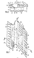
- Fig. 1
- zeigt die Aufsicht auf ein Deckband-Segment einer erfindungsgemäßen Turbinenschaufel,
- Fig. 2
- den Schnitt A-A aus Fig. 1,
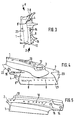
- Fig. 3
- die Ansicht X aus Fig. 1,
- Fig. 4
- die Ansicht Y aus Fig. 3, sowie
- Fig. 5
- die Ansicht Z aus Fig. 3.
- Mit der Bezugsziffer 1 ist eine gekühlte Turbinenschaufel einer Gasturbine bezeichnet, von der in Fig. 2 bis 5 lediglich die Schaufelspitze dargestellt ist. Diese Turbinenschaufel 1 trägt ein Deckband-Segment 2.
- Über die einzelnen Deckband-Segmente 2 eineinander benachbarter Turbinenschaufeln wird durch die Formgebung der Randflächen 22, 23 eine formschlüssige Verbindung zwischen diesen Turbinenschaufeln bzw. deren Deckband- Segmenten 2 hergestellt, so daß ein umlaufendes Schaufel-verstärkungsband gebildet wird.
- In der Turbinenschaufel 1 verläuft, wie bekannt, ein vorderer schaufelanströmseitiger Schaufel-Kühlluftkanal 3, sowie ein weiteres System von Kühlluftkanälen 13, die dem Schaufelmittenbereich sowie der Schaufelabströmkante zugeordnet sind. Dieses mittlere bzw. hintere Kühlkanal-system besteht dabei aus drei mäanderformig aneinandergereihten Kühlluft-Kanälen 13. Der schaufelanströmseitige Kühlluftkanal 3 sowie das weitere System von Kühl-luftkanälen 13 arbeiten unabhängig voneinander, d. h. die Kühlluftkanäle 3, 13 werden voneinander getrennt mit Kühlluft versorgt.
- Im Deckband-Segment 2 sind zwei Kühlluft-Stichkanäle 4, 14 sowie ein Parallel-Stichkanal 15 vorgesehen. Die Stichkanäle 4, 14 sowie der Parallel-Stichanal 15 verlaufen im wesentlichen parallel zueinander sowie im wesentlichen vertikal zur Längsachse der Turbinenschaufel 1 und sind wie ersichtlich im wesentlichen in Umfangsrichtung des durch eine Vielzahl von nebeneinanderliegenden Deckband-Segmenten 2 gebildeten, nicht gezeigten Schaufelverstärkungsbandes einer üblichen Turbinenschaufel-Anordnung orientiert.
- Nicht nur die Schaufel-Kühlluftkanäle 3, 13 werden voneinander unabhängig mit Kühlluft versorgt, sondern auch die an die Schaufel-Kühlluftkanäle angeschlossenen Kühlluft-Stichkanäle 4, 14 im Deckband-Segment 2. So ist über einen Verbindungskanal 6 der Kühlluft-Stichkanal 4 mit dem Schaufel-Kühlluftkanal 3 verbunden, d. h. der Kühlluft-Stichkanal 4 wird vom Schaufel-Kühlluftkanal 3 mit Kühlluft versorgt. Vom Kühlluft-Stichkanal 4 zweigen eine Vielzahl von Kühlluft-Bohrungen 7 ab, die zur Oberfläche des Deckband-Segmentes 2 führen und an dieser Oberfläche münden und dabei sog. Filmkühllöcher 8 oder Konvektions-Kühlungsbohrungen 8 bilden. Dies ermöglicht eine Konvek-tions-Kühlung im vorderen Bereich des Deckband-Segmentes 2 und zusätzlich eine Filmkühlung der Dichtkante 21 dieses Deckband-Segmentes. Gleichzeitig werden die einander benachbarten Randflächen 22, 23 der einzelnen Deckband-Segmente einander benachbarter Turbinenschaufeln insbesondere durch den über die Filmkühllöcher 8' austretenden Kühlluftstrom gekühlt.
- Über einen Verbindungskanal 16 ist det zweite Kühlluft-Stichkanal 14 mit dem Schaufel-Kühlluftkanal 13 verbunden. Auch vom zweiten Kühlluft-Stichkanal 14 zweigen Kühlluft-Bohrungen 9 ab, die als Filmkühllöcher 10 oder als Konvektions-Kühlungsbohrungen 10 ebenfalls an der Oberfläche des Deckband-Segmentes 2 münden. Gleichzeitig wird über diese Kühlluft-Bohrungen 9, die eine großflä-chige Kühlung des Deckband-Segmentes 2 gewährleisten, der Parallel-Stichkanal 15, der eine verbesserte Verteilung von Kühlluft bewirkt, mit Kühlluft versorgt. Dabei erstreckt sich lediglich ein Teil der Kühlluft-Bohrungen 9 von der Oberfläche des Deckband-Segmentes 2 über den Parallel-Stichkanal 15 hinaus bis zum Kühl-Stichkanal 14.
- Über die Anzahl dieser den Kühl-Stichkanal 14 mit dem Parallel-Stichkanal 15 verbindenden Kühlluft-Bohrungen 9 ist der in den Parallel-Stichkanal 15 gelangende Kühlluftstrom festlegbar.
- Die Kühlluft-Stichkanäle 4, 14 sowie der Parallel-Stichkanal 15 sind von relativ großem Querschnitt und werden durch Bohren erzeugt. An den Endseiten des Deckband-Segmentes 2 werden diese Kanäle verschlossen, beispielsweise durch Verschweißen. Mit den beiden Kühlluft-Stichkanälen 4, 14 sowie dem zusätzlichen Parallel-Stichkanal 15 sowie mit den Filmkühllöchern 8 und den zusätzlichen Konvektions-Kühllöchern oder Filmkühllöchern 10 ergibt sich eine gleichmäßige wirkungsvolle Kühlung nicht nur des Deckband-Segmentes 2, sondern auch von dessen Randflächen 22, 23 sowie dessen Dichtkante 21. Dabei können jedoch eine Vielzahl von Details durchaus abweichend vom gezeigten Ausführungsbeispiel gestaltet sein, ohne den Inhalt der Patentansprüche zu verlassen.
Claims (4)
- Turbinenschaufel einer Gasturbine mit zumindest einem in der Schaufel (1) verlaufenden Kühlluftkanal (3) sowie mit einem an der Schaufelspitze angeordneten Deckband-Segment (2), das gemeinsam mit weiteren Segmenten benachbarter Schaufeln ein Schaufelverstärkungsband bildet, ferner mit einem schaufelanströmseitig im Deckband-Segment (2) im wesentlichen vertikal zur Schaufelachse verlaufenden und mit dem im Schaufel-Anströmbereich liegenden Schaufel-Kühlluftkanal (3) verbundenen Kühlluft-Stichkanal (4), von dem aus mehrere Kühlluft-Bohrungen (7) zur Oberfläche des Deckband-Segmentes (2) führen, sowie mit einem weiteren im Deckband-Segment (2) verlaufenden Kühl-Stichkanal (14), der mit einem in der Schaufelmitte oder im Schaufelabströmbereich liegenden Schaufel-Kühlkanal (13) verbunden ist, von dem aus ebenfalls Kühlluft-Bohrungen (9) zur Oberfläche des Deckband-Segmentes (2) führen,
dadurch gekennzeichnet, daß zumindest ein weiterer, im wesentlichen parallel zum Kühl-Stichkanal (14) verlaufender Parallel-Stichkanal (15) vorgesehen ist, der mit dem Kühl-Stichkanal (14) über mehrere Kühlluft-Bohrungen (9) verbunden ist. - Turbinenschaufel nach Anspruch 1,
dadurch gekennzeichnet, daß die Stichkanäle (4, 14, 15) im wesentlichen in Richtung des umlaufenden Schaufelverstärkungsbandes orientiert und an den beiden Endseiten des Deckband-Segmentes (2) verschlossen sind. - Turbinenschaufel nach einem der vorangegangenen Ansprüche,
dadurch gekennzeichnet, daß die Kühlluft-Bohrungen (7, 9) im wesentlichen vertikal zur Schaufelachse verlaufen und sich von der Oberfläche des Deckband-Segmentes (2) bis zu einem Stichkanal (4, 15) oder darüber hinaus erstrecken. - Turbinenschaufel nach Anspruch 3,
dadurch gekennzeichnet, daß der Parallel-Stichkanal (15) im Schaufel-Abströmbereich liegt.
Applications Claiming Priority (3)
| Application Number | Priority Date | Filing Date | Title |
|---|---|---|---|
| GB9224241 | 1992-11-19 | ||
| GB929224241A GB9224241D0 (en) | 1992-11-19 | 1992-11-19 | A turbine blade arrangement |
| PCT/EP1993/003146 WO1994011616A1 (de) | 1992-11-19 | 1993-11-10 | Kühlung des deckbandes einer turbinenschaufel |
Publications (2)
| Publication Number | Publication Date |
|---|---|
| EP0621920A1 EP0621920A1 (de) | 1994-11-02 |
| EP0621920B1 true EP0621920B1 (de) | 1996-03-20 |
Family
ID=10725339
Family Applications (1)
| Application Number | Title | Priority Date | Filing Date |
|---|---|---|---|
| EP94901787A Expired - Lifetime EP0621920B1 (de) | 1992-11-19 | 1993-11-10 | Kühlung des deckbandes einer turbinenschaufel |
Country Status (5)
| Country | Link |
|---|---|
| US (1) | US5460486A (de) |
| EP (1) | EP0621920B1 (de) |
| DE (1) | DE59301968D1 (de) |
| GB (1) | GB9224241D0 (de) |
| WO (1) | WO1994011616A1 (de) |
Families Citing this family (41)
| Publication number | Priority date | Publication date | Assignee | Title |
|---|---|---|---|---|
| GB2290833B (en) * | 1994-07-02 | 1998-08-05 | Rolls Royce Plc | Turbine blade |
| US5482435A (en) * | 1994-10-26 | 1996-01-09 | Westinghouse Electric Corporation | Gas turbine blade having a cooled shroud |
| GB2298245B (en) * | 1995-02-23 | 1998-10-28 | Bmw Rolls Royce Gmbh | A turbine-blade arrangement comprising a cooled shroud band |
| GB2298246B (en) * | 1995-02-23 | 1998-10-28 | Bmw Rolls Royce Gmbh | A turbine-blade arrangement comprising a shroud band |
| JP3178327B2 (ja) * | 1996-01-31 | 2001-06-18 | 株式会社日立製作所 | 蒸気タービン |
| US5785496A (en) * | 1997-02-24 | 1998-07-28 | Mitsubishi Heavy Industries, Ltd. | Gas turbine rotor |
| JPH1113402A (ja) * | 1997-06-23 | 1999-01-19 | Mitsubishi Heavy Ind Ltd | ガスタービン冷却翼チップシュラウド |
| JP2955252B2 (ja) * | 1997-06-26 | 1999-10-04 | 三菱重工業株式会社 | ガスタービン動翼チップシュラウド |
| JP3510467B2 (ja) * | 1998-01-13 | 2004-03-29 | 三菱重工業株式会社 | ガスタービンの動翼 |
| EP0935052B1 (de) * | 1998-02-04 | 2006-05-03 | Mitsubishi Heavy Industries, Ltd. | Gasturbinenlaufschaufel |
| DE59912323D1 (de) | 1998-12-24 | 2005-09-01 | Alstom Technology Ltd Baden | Turbinenschaufel mit aktiv gekühltem Deckbandelememt |
| DE19904229A1 (de) * | 1999-02-03 | 2000-08-10 | Asea Brown Boveri | Gekühlte Turbinenschaufel |
| EP1041247B1 (de) * | 1999-04-01 | 2012-08-01 | General Electric Company | Gasturbinenschaufel mit einem offenen Kühlkreislauf |
| US6761534B1 (en) | 1999-04-05 | 2004-07-13 | General Electric Company | Cooling circuit for a gas turbine bucket and tip shroud |
| DE19963377A1 (de) * | 1999-12-28 | 2001-07-12 | Abb Alstom Power Ch Ag | Turbinenschaufel mit aktiv gekühltem Deckbandelement |
| DE10016081A1 (de) * | 2000-03-31 | 2001-10-04 | Alstom Power Nv | Plattenförmiger, auskragender Bauteilabschnitt einer Gasturbine |
| DE10064265A1 (de) | 2000-12-22 | 2002-07-04 | Alstom Switzerland Ltd | Vorrichtung und Verfahren zur Kühlung einer Plattform einer Turbinenschaufel |
| JP2002201913A (ja) * | 2001-01-09 | 2002-07-19 | Mitsubishi Heavy Ind Ltd | ガスタービンの分割壁およびシュラウド |
| US6506022B2 (en) * | 2001-04-27 | 2003-01-14 | General Electric Company | Turbine blade having a cooled tip shroud |
| US6887033B1 (en) * | 2003-11-10 | 2005-05-03 | General Electric Company | Cooling system for nozzle segment platform edges |
| EP1591625A1 (de) * | 2004-04-30 | 2005-11-02 | ALSTOM Technology Ltd | Deckband für eine Gasturbinenschaufel |
| EP1591626A1 (de) * | 2004-04-30 | 2005-11-02 | Alstom Technology Ltd | Schaufel für Gasturbine |
| EP1630354B1 (de) | 2004-08-25 | 2014-06-18 | Rolls-Royce Plc | Gekühlte Gasturbinenschaufel |
| US7686581B2 (en) * | 2006-06-07 | 2010-03-30 | General Electric Company | Serpentine cooling circuit and method for cooling tip shroud |
| US7762773B2 (en) * | 2006-09-22 | 2010-07-27 | Siemens Energy, Inc. | Turbine airfoil cooling system with platform edge cooling channels |
| US7611324B2 (en) * | 2006-11-30 | 2009-11-03 | General Electric Company | Method and system to facilitate enhanced local cooling of turbine engines |
| CH699593A1 (de) * | 2008-09-25 | 2010-03-31 | Alstom Technology Ltd | Schaufel für eine gasturbine. |
| GB0901129D0 (en) * | 2009-01-26 | 2009-03-11 | Rolls Royce Plc | Rotor blade |
| CH700686A1 (de) * | 2009-03-30 | 2010-09-30 | Alstom Technology Ltd | Schaufel für eine gasturbine. |
| US8356978B2 (en) * | 2009-11-23 | 2013-01-22 | United Technologies Corporation | Turbine airfoil platform cooling core |
| US9759070B2 (en) * | 2013-08-28 | 2017-09-12 | General Electric Company | Turbine bucket tip shroud |
| WO2017023258A1 (en) * | 2015-07-31 | 2017-02-09 | General Electric Company | Cooling arrangements in turbine blades |
| US10508554B2 (en) | 2015-10-27 | 2019-12-17 | General Electric Company | Turbine bucket having outlet path in shroud |
| US10156145B2 (en) | 2015-10-27 | 2018-12-18 | General Electric Company | Turbine bucket having cooling passageway |
| US9885243B2 (en) | 2015-10-27 | 2018-02-06 | General Electric Company | Turbine bucket having outlet path in shroud |
| US10202852B2 (en) | 2015-11-16 | 2019-02-12 | General Electric Company | Rotor blade with tip shroud cooling passages and method of making same |
| US10301945B2 (en) * | 2015-12-18 | 2019-05-28 | General Electric Company | Interior cooling configurations in turbine rotor blades |
| US10184342B2 (en) * | 2016-04-14 | 2019-01-22 | General Electric Company | System for cooling seal rails of tip shroud of turbine blade |
| US10502069B2 (en) * | 2017-06-07 | 2019-12-10 | General Electric Company | Turbomachine rotor blade |
| US10577945B2 (en) * | 2017-06-30 | 2020-03-03 | General Electric Company | Turbomachine rotor blade |
| US20190085706A1 (en) * | 2017-09-18 | 2019-03-21 | General Electric Company | Turbine engine airfoil assembly |
Family Cites Families (12)
| Publication number | Priority date | Publication date | Assignee | Title |
|---|---|---|---|---|
| FR1245518A (fr) * | 1957-04-19 | 1960-11-10 | Perfectionnements apportés aux turbines à fluide gazeux chaud | |
| US3529902A (en) * | 1968-05-22 | 1970-09-22 | Gen Motors Corp | Turbine vane |
| BE755567A (fr) * | 1969-12-01 | 1971-02-15 | Gen Electric | Structure d'aube fixe, pour moteur a turbines a gaz et arrangement de reglage de temperature associe |
| GB1605335A (en) * | 1975-08-23 | 1991-12-18 | Rolls Royce | A rotor blade for a gas turbine engine |
| US4017213A (en) * | 1975-10-14 | 1977-04-12 | United Technologies Corporation | Turbomachinery vane or blade with cooled platforms |
| GB1514613A (en) * | 1976-04-08 | 1978-06-14 | Rolls Royce | Blade or vane for a gas turbine engine |
| US4353679A (en) * | 1976-07-29 | 1982-10-12 | General Electric Company | Fluid-cooled element |
| JP2862536B2 (ja) * | 1987-09-25 | 1999-03-03 | 株式会社東芝 | ガスタービンの翼 |
| GB2223276B (en) * | 1988-09-30 | 1992-09-02 | Rolls Royce Plc | Turbine aerofoil blade |
| GB2228540B (en) * | 1988-12-07 | 1993-03-31 | Rolls Royce Plc | Cooling of turbine blades |
| GB2250548A (en) * | 1990-12-06 | 1992-06-10 | Rolls Royce Plc | Cooled turbine aerofoil blade |
| US5344283A (en) * | 1993-01-21 | 1994-09-06 | United Technologies Corporation | Turbine vane having dedicated inner platform cooling |
-
1992
- 1992-11-19 GB GB929224241A patent/GB9224241D0/en active Pending
-
1993
- 1993-11-10 DE DE59301968T patent/DE59301968D1/de not_active Expired - Fee Related
- 1993-11-10 US US08/256,647 patent/US5460486A/en not_active Expired - Fee Related
- 1993-11-10 WO PCT/EP1993/003146 patent/WO1994011616A1/de not_active Ceased
- 1993-11-10 EP EP94901787A patent/EP0621920B1/de not_active Expired - Lifetime
Also Published As
| Publication number | Publication date |
|---|---|
| US5460486A (en) | 1995-10-24 |
| EP0621920A1 (de) | 1994-11-02 |
| WO1994011616A1 (de) | 1994-05-26 |
| GB9224241D0 (en) | 1993-01-06 |
| DE59301968D1 (de) | 1996-04-25 |
Similar Documents
| Publication | Publication Date | Title |
|---|---|---|
| EP0621920B1 (de) | Kühlung des deckbandes einer turbinenschaufel | |
| DE69815735T2 (de) | Gekühlte Gasturbinenlaufschaufel | |
| DE2930949C2 (de) | ||
| EP1223308B1 (de) | Komponente einer Strömungsmaschine | |
| DE3211139C1 (de) | Axialturbinenschaufel,insbesondere Axialturbinenlaufschaufel fuer Gasturbinentriebwerke | |
| DE69823236T2 (de) | Einrichtung zur kühlung von gasturbinenschaufeln und methode zu deren herstellung | |
| DE1946535C3 (de) | Bauteil für ein Gasturbinentriebwerk | |
| EP0798448B1 (de) | Vorrichtung und Verfahren zur Kühlung einer einseitig von Heissgas umgebenen Wand | |
| DE10355449B4 (de) | Turbinenschaufel | |
| EP0265726B1 (de) | Wärmetauscher | |
| DE2413292A1 (de) | Blattkuehleinsatzhalter fuer turbomaschinen | |
| EP0985802A1 (de) | Filmkühlbohrung und Verfahren zur Herstellung derselben | |
| DE2241194A1 (de) | Stroemungsmaschinenschaufel mit tragfluegelfoermigem querschnittsprofil und mit einer vielzahl von in schaufellaengsrichtung verlaufenden kuehlkanaelen | |
| DE2417801A1 (de) | Verbesserte struktur zur eindaemmung von leckage | |
| DE69828023T2 (de) | Deckband für gekühlte gasturbinenschaufeln | |
| DE19601818A1 (de) | Turbinenschaufel-Anordnung mit einem Deckband | |
| DE112020002736T5 (de) | Fluidkompressor und verfahren zum betrieb eines fluidkompressorszur verringerung der ölverschleppung durch eine kompressorkolbenbaugruppe | |
| EP0931600B1 (de) | Vorrichtung zum Entzundern von Walzgut | |
| DE602004006035T2 (de) | Kühleinrichtung für Turbinenscheiben | |
| DE2155344A1 (de) | Integrales turbinenrad mit offenen axialen durchbruechen am aeusseren kranz und kontrollierten kranzrissen | |
| DE1118374B (de) | Elektroerosives Verfahren zur Herstellung von Ausnehmungen in Werkstuecken aus leitendem Material | |
| EP1288435B1 (de) | Turbinenschaufel mit zumindest einer Kühlungsöffnung | |
| EP1138878B1 (de) | Bauteil einer Gasturbine | |
| DE19601819A1 (de) | Turbinenschaufel-Anordnung mit einem gekühlten Deckband | |
| DE3504343A1 (de) | Saegeblatt |
Legal Events
| Date | Code | Title | Description |
|---|---|---|---|
| PUAI | Public reference made under article 153(3) epc to a published international application that has entered the european phase |
Free format text: ORIGINAL CODE: 0009012 |
|
| 17P | Request for examination filed |
Effective date: 19940727 |
|
| AK | Designated contracting states |
Kind code of ref document: A1 Designated state(s): DE FR GB IT SE |
|
| 17Q | First examination report despatched |
Effective date: 19950526 |
|
| GRAA | (expected) grant |
Free format text: ORIGINAL CODE: 0009210 |
|
| AK | Designated contracting states |
Kind code of ref document: B1 Designated state(s): DE FR GB IT SE |
|
| ET | Fr: translation filed | ||
| REF | Corresponds to: |
Ref document number: 59301968 Country of ref document: DE Date of ref document: 19960425 |
|
| GBT | Gb: translation of ep patent filed (gb section 77(6)(a)/1977) |
Effective date: 19960328 |
|
| ITF | It: translation for a ep patent filed | ||
| PLBE | No opposition filed within time limit |
Free format text: ORIGINAL CODE: 0009261 |
|
| STAA | Information on the status of an ep patent application or granted ep patent |
Free format text: STATUS: NO OPPOSITION FILED WITHIN TIME LIMIT |
|
| 26N | No opposition filed | ||
| REG | Reference to a national code |
Ref country code: FR Ref legal event code: CD |
|
| REG | Reference to a national code |
Ref country code: FR Ref legal event code: CJ Ref country code: FR Ref legal event code: CA |
|
| REG | Reference to a national code |
Ref country code: GB Ref legal event code: IF02 |
|
| PGFP | Annual fee paid to national office [announced via postgrant information from national office to epo] |
Ref country code: FR Payment date: 20041010 Year of fee payment: 12 |
|
| PGFP | Annual fee paid to national office [announced via postgrant information from national office to epo] |
Ref country code: GB Payment date: 20041014 Year of fee payment: 12 |
|
| PGFP | Annual fee paid to national office [announced via postgrant information from national office to epo] |
Ref country code: SE Payment date: 20041020 Year of fee payment: 12 Ref country code: DE Payment date: 20041020 Year of fee payment: 12 |
|
| PG25 | Lapsed in a contracting state [announced via postgrant information from national office to epo] |
Ref country code: IT Free format text: LAPSE BECAUSE OF NON-PAYMENT OF DUE FEES Effective date: 20051110 Ref country code: GB Free format text: LAPSE BECAUSE OF NON-PAYMENT OF DUE FEES Effective date: 20051110 |
|
| PG25 | Lapsed in a contracting state [announced via postgrant information from national office to epo] |
Ref country code: SE Free format text: LAPSE BECAUSE OF NON-PAYMENT OF DUE FEES Effective date: 20051111 |
|
| PG25 | Lapsed in a contracting state [announced via postgrant information from national office to epo] |
Ref country code: DE Free format text: LAPSE BECAUSE OF NON-PAYMENT OF DUE FEES Effective date: 20060601 |
|
| EUG | Se: european patent has lapsed | ||
| GBPC | Gb: european patent ceased through non-payment of renewal fee |
Effective date: 20051110 |
|
| PG25 | Lapsed in a contracting state [announced via postgrant information from national office to epo] |
Ref country code: FR Free format text: LAPSE BECAUSE OF NON-PAYMENT OF DUE FEES Effective date: 20060731 |
|
| REG | Reference to a national code |
Ref country code: FR Ref legal event code: ST Effective date: 20060731 |