EP0622005A1 - Méthode de préparation du sol pour la plantation et machine pour sa réalisation - Google Patents
Méthode de préparation du sol pour la plantation et machine pour sa réalisation Download PDFInfo
- Publication number
- EP0622005A1 EP0622005A1 EP94103664A EP94103664A EP0622005A1 EP 0622005 A1 EP0622005 A1 EP 0622005A1 EP 94103664 A EP94103664 A EP 94103664A EP 94103664 A EP94103664 A EP 94103664A EP 0622005 A1 EP0622005 A1 EP 0622005A1
- Authority
- EP
- European Patent Office
- Prior art keywords
- machine
- rotavator
- soil
- rotavators
- wheels
- Prior art date
- Legal status (The legal status is an assumption and is not a legal conclusion. Google has not performed a legal analysis and makes no representation as to the accuracy of the status listed.)
- Withdrawn
Links
Images


Classifications
-
- A—HUMAN NECESSITIES
- A01—AGRICULTURE; FORESTRY; ANIMAL HUSBANDRY; HUNTING; TRAPPING; FISHING
- A01B—SOIL WORKING IN AGRICULTURE OR FORESTRY; PARTS, DETAILS, OR ACCESSORIES OF AGRICULTURAL MACHINES OR IMPLEMENTS, IN GENERAL
- A01B33/00—Tilling implements with rotary driven tools, e.g. in combination with fertiliser distributors or seeders, with grubbing chains, with sloping axles, with driven discs
- A01B33/02—Tilling implements with rotary driven tools, e.g. in combination with fertiliser distributors or seeders, with grubbing chains, with sloping axles, with driven discs with tools on horizontal shaft transverse to direction of travel
- A01B33/021—Tilling implements with rotary driven tools, e.g. in combination with fertiliser distributors or seeders, with grubbing chains, with sloping axles, with driven discs with tools on horizontal shaft transverse to direction of travel with rigid tools
-
- A—HUMAN NECESSITIES
- A01—AGRICULTURE; FORESTRY; ANIMAL HUSBANDRY; HUNTING; TRAPPING; FISHING
- A01B—SOIL WORKING IN AGRICULTURE OR FORESTRY; PARTS, DETAILS, OR ACCESSORIES OF AGRICULTURAL MACHINES OR IMPLEMENTS, IN GENERAL
- A01B79/00—Methods for working soil
Definitions
- the invention relates to a method for mechanical tillage of areas to be planted, in particular forest areas to be planted with trees, according to the features of the preamble of claim 1.
- the invention further relates to a tillage machine for carrying out the method.
- the ground where the plant is to be used is traditionally hoisted with a hoop hoe, the plant is inserted and the soil around the Then plant planted. Not only is this procedure time consuming and physically demanding, it also leads to relatively poor planting results. For a good growth of the plants, it is necessary that the soil is loosened sufficiently to a depth of about 50 cm and a width of about 30 cm, which can practically not be done manually with a hoe.
- the applicant has also developed a planting method in which a wedge, which is attached to a handle and is open at the rear, is pulled through an excavator towards the bottom.
- the wedge splits the soil, so that the plants can be used accordingly deep.
- the main disadvantage of this method is that the soil is strongly compacted by splitting on the right and left. As a result, the soil can no longer be walked on properly after planting.
- the invention is based on the object of specifying an automated, environmentally friendly and soil-protecting method for cultivating areas to be planted, which is both cost-effective and efficient and also contributes to improving the forest floor. Furthermore, a tillage machine is to be specified with the aid of which the method according to the invention can be carried out on forest areas and wasteland.
- the task is characterized by the features of the characterizing part of the Claim 1 solved. It is then proposed to loosen the soil to be planted only in the lane area of the soil planting machine and then to introduce the plants into this area.
- the respective track distances are chosen such that they correspond to the distances of the desired rows of plants.
- the area between the lanes - i.e. at a planting distance of 3 m, i.e. approx. 80% of the forest floor - remains unaffected.
- the rotavators are preferably arranged at a variable height on the rear part of the towing vehicle, so that they can move upward when hitting solid objects.
- the wheel axles are arranged so that they can be moved laterally outwards.
- a substrate container is preferably arranged on the soil cultivation machine, which is connected to screw conveyors which convey the substrate into the vehicle tracks immediately in front of the rotavators.
- the machine can be used both for preparing the plant bed in summer / autumn (planting in autumn / spring) and for preparing the bed with simultaneous planting.
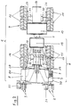
- FIG. 1 denotes a tillage machine, on the rear of which planting units 2 and 3 (FIG. 2) are arranged.
- the tillage machine 1 is an 8-wheel articulated vehicle which consists of a front vehicle part 4 arranged in front of the articulated joint 5 and a rear vehicle part 6 arranged behind the articulated joint 5.
- the front vehicle part 4 of the tillage machine 1 has an engine block 10 which is mounted on two pairs of wheels 11, 12. Furthermore, there is a plant space container 13 for storing plants 14, if possible for the entire area to be planted.
- the rear vehicle part 6 of the tillage machine 1 also has two pairs of wheels 15, 16 which are fastened to a frame part which is not shown in detail.
- Rotavator wheels 9 are each arranged in a housing 70, 80 which is open towards the forest floor.
- a substrate container 18 is attached to this vehicle part, which is connected to two screw conveyors 19, 20. These transport the respective substrate - usually lime for soil fertilization metered into the vehicle track in front of the rotavators 7, 8.
- Two plant containers 21, 22 are provided on the planting units 2, 3, from which the corresponding plants 23 are removed by the operating personnel 24, 25 for insertion into the loosened soil.
- axles designated in FIG. 2 with 26, 27 or 28, 29, to which the wheel pairs 11, 12 or 15, 16 are attached are axially variable (so-called. Boogie axes) are formed. Because with such boogie axes, it is possible to use the tillage machine 1 on non-cleared surfaces with an incline of up to 30 degrees, whereby obstacles of up to 80 cm in height can be overcome.
- the wheel axles 26-29 and thus also the wheel pairs 11-16 are arranged to be displaceable in the axial direction, ie laterally outwards. This ensures that the distance between the vehicle tracks varies and can be adapted to the required planting row spacing.
- the displaceability of the wheel axles 26-29 is realized by means of corresponding controllable hydraulic cylinders 30-33, which are arranged on the wheel axles 26-29 (the hydraulic cylinders are dimensioned such that the lane distance and thus the planting row distance can be varied between 2 and 3 m ).
- the 8 wheels 11, 12, 15, 16 were provided with 70 cm wide tires. This results in an extremely low soil pressure (approx. 0.1 kg / cm2), so that practically no notable soil compaction takes place by driving over the soil in the lane area.
- the operator walks alongside the soil cultivation machine 1 during soil cultivation, because this enables him to keep an eye on all the essential functional parts. In particular, he can precisely control the work of the rotavators 7, 8 and readjust them as required.
- FIG. 3 shows a side view of the rotavator 7 with the rotavator wheel 9.
- the rotavator housing 70 which is open at the bottom, is shown in dashed lines.
- a plurality of cutting blades 90-92 are arranged axially and circumferentially on the rotavator wheel 9. In total, in this embodiment, 12 cutting blades are used between the respective outside and the center of the rotavator wheel, in such a way that four cutting blades always have the same axial distance.
- Interchangeable chisels 93-95 made of hardened steel are arranged on the outer ends of the cutting swords 90-92.
- the direction of rotation of the rotavator wheel 9 is identified by the reference symbol 96 and the direction of movement of the rotavator 7 by 71.
- FIG. 4 shows a development of part of the lateral surface 40 of the Rotavatorrad 9.
- the cutting swords are shown as rectangles.
- the cutting swords shown in FIG. 3 are again designated by 90-92. This is followed by the cutting swords 97-99 on the side facing the viewer.
- Corresponding cutting swords are arranged on the side facing away from the viewer, only three being shown in FIG. 4, which are provided with the reference numerals 100-102.
- the process of transporting the earth towards the center of the rotavator wheel is supported in that the cutting swords 90-92, 97-102, viewed in the direction of rotation 96, are inclined with respect to the center line 45 of the lateral surface 40 of the rotavator wheel.
- the corresponding angle of inclination 103 of the cutting swords depends on the number of cutting swords used and their width and is approximately 5 ° in the exemplary embodiment shown.
- the rotavators 7, 8 cause a 50 cm deep loosening of the soil in a 30 cm wide track (in the following also referred to as the milling track) and thus create the conditions for an optimal introduction and growth of the plants.
- the width of the milling track does not necessarily have to be identical to the respective tire track, but can also be narrower or wider than this.
- the milling track width of 30 cm was chosen because it was found in tests that the soil only remained in its loose structure up to a milling width of approx. 30 cm.
- the direction of rotation 96 of the rotavator wheels 9 is selected in exactly the opposite direction to the direction of rotation of the vehicle wheels 11, 12, 15, 16 which determine the direction of travel. This avoids the formation of a compaction on the milling sole. In this case, the earth is transported from bottom to top, conveyed through the rotavator housings 70, 80 and falls loosely back into the milling track on the back of the rotavators 7, 8. If, on the other hand, the rotavator wheels 9 had the same direction of rotation as the vehicle wheels 11, 12, 15, 16, the earth would be pressed from top to bottom and thus strongly compacted below. This would lead to water build-up, prevent good ventilation of the soil and hinder the roots from growing downwards.
- the speed of rotation of the rotavator wheels 9 should preferably be matched to the speed of the tillage machine 1; namely, the Rotavator wheels 9 should rotate so slowly that a coarse crumb structure of the ground is achieved, which is important for optimal ventilation.
- the number of revolutions of the rotavator wheels 9 is selected at a predetermined vehicle speed such that each cutting blade 90-92, 97-102 cuts the ground only once. This means in particular that the cutting blade 97 does not engage in the soil that has already been loosened by the cutting blade 90, but the number of revolutions of the rotavator wheels 9 is so slow that the cutting blade 97 engages in a soil section that has not yet been loosened.
- the rotavators 7, 8 are connected to the actuators (pulling cylinders) 17 because they pull into the ground due to the opposite direction of rotation of the rotavator wheels 9 compared to the vehicle wheels 11, 12, 15, 16. So that the cutting blades 90-92, 97-102 do not work deeper than 50 cm into the ground, the cylinders 17 exert an opposing tensile force that is not greater than the dead weight of the respective rotavator 7, 8 (approx. 1 t). The rotavators 7 thus remain 8 always at the desired level for a planting depth of 50 cm.
- the rotavator wheels 9 hit an obstacle (e.g. a large stone or a tree stump), the resistance of which is greater than the rotational force of the rotavator wheels 9, the wheels 9 automatically switch to freewheeling when a limit pressure is reached. As a result, the respective rotavator wheel 9 can roll over the obstacle without changing the driving speed of the machine 1.
- an obstacle e.g. a large stone or a tree stump
- the planting units 2, 3 arranged behind the rotavators 7, 8 can be coupled directly to the wheel arches of the rotavators 7, 8 during wasteland reforestation because there are no vertical evasive movements upwards in the wasteland due to the lack of larger obstacles.
- the planting units 2, 3 are attached to traction cylinders which are fastened independently of the rotavators 7, 8, so that when they encounter a larger obstacle, they can perform height evasive movements independently of the movements of the rotavators 7, 8 and the tillage machine 1.
Landscapes
- Life Sciences & Earth Sciences (AREA)
- Engineering & Computer Science (AREA)
- Mechanical Engineering (AREA)
- Soil Sciences (AREA)
- Environmental Sciences (AREA)
- Soil Working Implements (AREA)
Applications Claiming Priority (2)
| Application Number | Priority Date | Filing Date | Title |
|---|---|---|---|
| DE4314234 | 1993-04-30 | ||
| DE19934314234 DE4314234C2 (de) | 1993-04-30 | 1993-04-30 | Verfahren zur Bodenbearbeitung von zu bepflanzenden Flächen und Bodenbearbeitungsmaschine zur Durchführung des Verfahrens |
Publications (1)
| Publication Number | Publication Date |
|---|---|
| EP0622005A1 true EP0622005A1 (fr) | 1994-11-02 |
Family
ID=6486805
Family Applications (1)
| Application Number | Title | Priority Date | Filing Date |
|---|---|---|---|
| EP94103664A Withdrawn EP0622005A1 (fr) | 1993-04-30 | 1994-03-10 | Méthode de préparation du sol pour la plantation et machine pour sa réalisation |
Country Status (2)
| Country | Link |
|---|---|
| EP (1) | EP0622005A1 (fr) |
| DE (1) | DE4314234C2 (fr) |
Cited By (1)
| Publication number | Priority date | Publication date | Assignee | Title |
|---|---|---|---|---|
| WO2000072654A1 (fr) * | 1999-05-31 | 2000-12-07 | Magotteaux International | Rotor pour broyeur a usage forestier |
Families Citing this family (3)
| Publication number | Priority date | Publication date | Assignee | Title |
|---|---|---|---|---|
| DE29722403U1 (de) * | 1997-12-18 | 1998-02-26 | Straub, Johann Baptist, 88239 Wangen | Bagger |
| DE102005020563A1 (de) * | 2005-02-17 | 2006-08-31 | Heiß jun., Andreas | Kombinierte landwirtschaftliche Maschine |
| DE112006000110B4 (de) | 2005-02-17 | 2026-03-12 | Andreas Heiß jun. | Kombinierte landwirtschaftliche Maschine |
Citations (6)
| Publication number | Priority date | Publication date | Assignee | Title |
|---|---|---|---|---|
| FR2446583A1 (fr) * | 1979-01-18 | 1980-08-14 | Serlachius Oy | Dispositif de preparation du sol pour une machine motrice, notamment une machine de plantation, utilisee dans les exploitations forestieres |
| GB2051703A (en) * | 1979-06-20 | 1981-01-21 | Stevenson J | Articulated height adjustable vehicle |
| DE3149662A1 (de) * | 1980-12-16 | 1982-08-12 | Mo och Domsjö AB, 89101 Örnsköldsvik | Bodenbearbeitungsverfahren insbesondere fuer die forstregeneration und vorrichtung zur durchfuehrung des verfahrens |
| DE3417760A1 (de) * | 1984-05-12 | 1985-11-14 | Ludwig Euroley Müller | Landwirtschaftlicher geraetetraeger fuer reihen- und beetkulturen |
| DE3431560A1 (de) * | 1984-08-28 | 1986-03-13 | Karl 4799 Borchen Meinberg | Anbaugeraet zur bearbeitung und duengung von waldboeden |
| US5082063A (en) * | 1990-08-23 | 1992-01-21 | Her Majesty The Queen In Right Of Canada As Represented By The Minister Of Forestry | Mixing head for soil tillage |
Family Cites Families (5)
| Publication number | Priority date | Publication date | Assignee | Title |
|---|---|---|---|---|
| GB1369666A (en) * | 1970-09-17 | 1974-10-09 | Cantone N | Process for intensive cultivation of the soil |
| DD150139A1 (de) * | 1980-04-23 | 1981-08-19 | Burkhard Koehler | Forstpflanzmaschine |
| DE3344113A1 (de) * | 1983-12-07 | 1985-06-20 | Landmaschinen Christian Schmidt MELIO-Maschinenbau KG, 2882 Ovelgönne | Rotierender fraeskoerper einer grabenprofilfraese, bankettfraese oder dergleichen |
| NL8500758A (nl) * | 1985-03-15 | 1986-10-01 | Texas Industries Inc | Trekker. |
| DE3843689A1 (de) * | 1988-12-23 | 1990-07-05 | Bayerische Motoren Werke Ag | Radaufhaengung fuer fahrzeuge mit veraenderbarer bodenfreiheit |
-
1993
- 1993-04-30 DE DE19934314234 patent/DE4314234C2/de not_active Expired - Fee Related
-
1994
- 1994-03-10 EP EP94103664A patent/EP0622005A1/fr not_active Withdrawn
Patent Citations (6)
| Publication number | Priority date | Publication date | Assignee | Title |
|---|---|---|---|---|
| FR2446583A1 (fr) * | 1979-01-18 | 1980-08-14 | Serlachius Oy | Dispositif de preparation du sol pour une machine motrice, notamment une machine de plantation, utilisee dans les exploitations forestieres |
| GB2051703A (en) * | 1979-06-20 | 1981-01-21 | Stevenson J | Articulated height adjustable vehicle |
| DE3149662A1 (de) * | 1980-12-16 | 1982-08-12 | Mo och Domsjö AB, 89101 Örnsköldsvik | Bodenbearbeitungsverfahren insbesondere fuer die forstregeneration und vorrichtung zur durchfuehrung des verfahrens |
| DE3417760A1 (de) * | 1984-05-12 | 1985-11-14 | Ludwig Euroley Müller | Landwirtschaftlicher geraetetraeger fuer reihen- und beetkulturen |
| DE3431560A1 (de) * | 1984-08-28 | 1986-03-13 | Karl 4799 Borchen Meinberg | Anbaugeraet zur bearbeitung und duengung von waldboeden |
| US5082063A (en) * | 1990-08-23 | 1992-01-21 | Her Majesty The Queen In Right Of Canada As Represented By The Minister Of Forestry | Mixing head for soil tillage |
Cited By (1)
| Publication number | Priority date | Publication date | Assignee | Title |
|---|---|---|---|---|
| WO2000072654A1 (fr) * | 1999-05-31 | 2000-12-07 | Magotteaux International | Rotor pour broyeur a usage forestier |
Also Published As
| Publication number | Publication date |
|---|---|
| DE4314234C2 (de) | 1997-08-21 |
| DE4314234A1 (de) | 1994-11-03 |
Similar Documents
| Publication | Publication Date | Title |
|---|---|---|
| DE4105934C2 (de) | Vorrichtung zum Umsetzen von in Mieten gelagertem Kompost | |
| DE2616545A1 (de) | Wurzel- und stengelshredder | |
| EP0025568A1 (fr) | Procédé et outil pour l'ameublissement du sol | |
| DE2355802A1 (de) | Verfahren und vorrichtung zur bodenlockerung | |
| DE3545970A1 (de) | Verfahren und vorrichtung zur auflockerung von boeden | |
| DE4314234C2 (de) | Verfahren zur Bodenbearbeitung von zu bepflanzenden Flächen und Bodenbearbeitungsmaschine zur Durchführung des Verfahrens | |
| EP2835043B1 (fr) | Semoir combiné agricole tracté et procédé de transfert d'un semoir combiné agricole d'une position de transport en position de travail et inversement | |
| DD235992A5 (de) | Arbeitsverfahren zur aufbereitung als ackerbodens sowie eine geraetekombination zur durchfuehrung des verfahrens | |
| EP0245780B1 (fr) | Méthode et dispositif pour travailler de la terre cultivable, en particulier de la terre de forêt | |
| WO1995028076A1 (fr) | Outil pour le travail du sol | |
| EP0211967A1 (fr) | Combinaison d'outils de travail de la terre utilisée en agriculture | |
| EP0316830B1 (fr) | Dispositif d'extraction pour une motte de terre ainsi que déracineuse pour plantes en ligne | |
| DE4314233C2 (de) | Bodenbearbeitungsmaschine | |
| DE102008002038B4 (de) | Bodenbearbeitungsgerät und Verfahren zur Bearbeitung verkrusteter Böden | |
| DE3417760A1 (de) | Landwirtschaftlicher geraetetraeger fuer reihen- und beetkulturen | |
| DE4002172C1 (en) | Agricultural implement for preparing soil - has self propelled vehicle with platform which has movable working arm | |
| DE8717049U1 (de) | Geräteantriebsaggregat für landwirtschaftliche Zwecke | |
| DE102020100257A1 (de) | Landwirtschaftliche Bodenbearbeitungsvorrichtung | |
| DE2554746A1 (de) | Vorrichtung zur bearbeitung grossflaechiger abschnitte von nutzungsflaechen | |
| DE3327568A1 (de) | Mehrfach-geraetekombination fuer traktoren zur bodenlockerung, saatbettherrichtung und bestellung | |
| DE1225911B (de) | Mehrzweck-Arbeitsfahrzeug zur Pflanzenkultur in Reihen | |
| DE202023001791U1 (de) | Vorrichtung zum Folienschneiden einer auf einem Damm aufgelegten Folie | |
| EP3679775A1 (fr) | Cadre combiné à trois points | |
| EP0077850A1 (fr) | Machine pour le travail du sol | |
| DE102005020563A1 (de) | Kombinierte landwirtschaftliche Maschine |
Legal Events
| Date | Code | Title | Description |
|---|---|---|---|
| PUAI | Public reference made under article 153(3) epc to a published international application that has entered the european phase |
Free format text: ORIGINAL CODE: 0009012 |
|
| AK | Designated contracting states |
Kind code of ref document: A1 Designated state(s): AT BE DE ES FR GB GR IE IT LU NL SE |
|
| 17P | Request for examination filed |
Effective date: 19950221 |
|
| 17Q | First examination report despatched |
Effective date: 19960619 |
|
| GRAG | Despatch of communication of intention to grant |
Free format text: ORIGINAL CODE: EPIDOS AGRA |
|
| GRAG | Despatch of communication of intention to grant |
Free format text: ORIGINAL CODE: EPIDOS AGRA |
|
| GRAH | Despatch of communication of intention to grant a patent |
Free format text: ORIGINAL CODE: EPIDOS IGRA |
|
| RAP1 | Party data changed (applicant data changed or rights of an application transferred) |
Owner name: N.F.T. NATURNAHE FORSTTECHNIK GMBH |
|
| STAA | Information on the status of an ep patent application or granted ep patent |
Free format text: STATUS: THE APPLICATION IS DEEMED TO BE WITHDRAWN |
|
| 18D | Application deemed to be withdrawn |
Effective date: 19990209 |