EP0622009A1 - Machine de fauchage - Google Patents
Machine de fauchage Download PDFInfo
- Publication number
- EP0622009A1 EP0622009A1 EP94201496A EP94201496A EP0622009A1 EP 0622009 A1 EP0622009 A1 EP 0622009A1 EP 94201496 A EP94201496 A EP 94201496A EP 94201496 A EP94201496 A EP 94201496A EP 0622009 A1 EP0622009 A1 EP 0622009A1
- Authority
- EP
- European Patent Office
- Prior art keywords
- crusher
- mower
- frame
- cutter bar
- mowing
- Prior art date
- Legal status (The legal status is an assumption and is not a legal conclusion. Google has not performed a legal analysis and makes no representation as to the accuracy of the status listed.)
- Granted
Links
- 229910000639 Spring steel Inorganic materials 0.000 claims description 3
- 230000005540 biological transmission Effects 0.000 description 6
- 230000008878 coupling Effects 0.000 description 3
- 238000010168 coupling process Methods 0.000 description 3
- 238000005859 coupling reaction Methods 0.000 description 3
- 238000005452 bending Methods 0.000 description 2
- 238000006073 displacement reaction Methods 0.000 description 2
- 239000002184 metal Substances 0.000 description 2
- 239000000725 suspension Substances 0.000 description 2
- 238000010276 construction Methods 0.000 description 1
- 230000000694 effects Effects 0.000 description 1
- 239000004744 fabric Substances 0.000 description 1
- 239000000463 material Substances 0.000 description 1
- 238000000034 method Methods 0.000 description 1
- 238000012986 modification Methods 0.000 description 1
- 230000004048 modification Effects 0.000 description 1
- 239000000126 substance Substances 0.000 description 1
Images




Classifications
-
- A—HUMAN NECESSITIES
- A01—AGRICULTURE; FORESTRY; ANIMAL HUSBANDRY; HUNTING; TRAPPING; FISHING
- A01D—HARVESTING; MOWING
- A01D43/00—Mowers combined with apparatus performing additional operations while mowing
- A01D43/10—Mowers combined with apparatus performing additional operations while mowing with means for crushing or bruising the mown crop
- A01D43/107—Mounting means
-
- A—HUMAN NECESSITIES
- A01—AGRICULTURE; FORESTRY; ANIMAL HUSBANDRY; HUNTING; TRAPPING; FISHING
- A01D—HARVESTING; MOWING
- A01D34/00—Mowers; Mowing apparatus of harvesters
- A01D34/01—Mowers; Mowing apparatus of harvesters characterised by features relating to the type of cutting apparatus
- A01D34/412—Mowers; Mowing apparatus of harvesters characterised by features relating to the type of cutting apparatus having rotating cutters
- A01D34/63—Mowers; Mowing apparatus of harvesters characterised by features relating to the type of cutting apparatus having rotating cutters having cutters rotating about a vertical axis
- A01D34/64—Mowers; Mowing apparatus of harvesters characterised by features relating to the type of cutting apparatus having rotating cutters having cutters rotating about a vertical axis mounted on a vehicle, e.g. a tractor, or drawn by an animal or a vehicle
- A01D34/66—Mowers; Mowing apparatus of harvesters characterised by features relating to the type of cutting apparatus having rotating cutters having cutters rotating about a vertical axis mounted on a vehicle, e.g. a tractor, or drawn by an animal or a vehicle with two or more cutters
- A01D34/664—Disc cutter bars
Definitions
- the present invention relates to a mower-crusher comprising a cutter bar which extends substantially transversely to the direction of operative travel over the field and mowing members arranged thereabove, which cutter bar is connected for its support in at least two places to a carrier frame, the mower-crusher furthermore comprising a crusher device.
- a mower crusher of the above-defined type is generally known.
- the cutter bar By connecting the cutter bar to the carrier frame in at least two places there is obtained framework which to a high extend absorbs the forces acting on the cutter bar in a direction opposite to the direction of operative travel of the mowing machine.
- the cutter bar in particularly when it is relative long and provided with a relatively heavy crusher device, is subjected to forces which are directed upwardly in a vertical plane and may course deformation thereof. This deformation results in an increased tension in the positions where the said connections to the cutter bar and the carrier frame are provided. The results thereof may manifest themselves in an unwanted wear of the transmission system which passes through the cutter bar and is required for the driving of the mowing members.
- the invention has for each object to improve this tension relief.
- a connection between the carrier frame and the cutter bar extends via the crusher device, resilient element being arranged between the crusher device and the cutter bar.
- This resilient element renders it possible to reduce to a significant extend not only the bending moments occuring in the connection but also the forces acting in the longitudinal direction of the cutter bar.
- the cutter bar is constituted by a supporting beam to which one end of the resilient element is connected while the other end of the resilient element is connected to a frame part of the crusher device.
- the resilient element is connected to the lower end of the frame. It is thus possible to have a relative simple construction in which the framework to a sufficient extent retends the possibility of observing the forces exerted in a direction opposite to the direction of operative travel.
- the cutter bar is not only provided between the cutter bar and the carrier frame at least one connection having a resilient element but the cutter bar is also connected in at least one position to the carrier frame via the relevant outermost mowing member.
- the second connection is constituted by a pivot whose pivot shaft extends substantially horizontally in the direction of operative travel of the mowing machine.
- the mower-crusher disclosed here can be moved by a tractor both on the side mounted and has a front mounted machine.
- the mower-crusher as shown in plan view ( Figure 1), in side view ( Figure 3) and in partial rear view ( Figure 2), is provided with a pivotal arm 1, by means of which it can be connected to a tractor. Via a pivot 2 the pivotal arm 1 is connected to a first frame 3 which is supported drivably by means of wheels 4. The wheels 4 are pivotably connected to the first frame 3 by means of pivots 5. The pivotal movement of each of the wheels relative to the first frame 3 is effected by means of a hydraulic cylinder 6.
- the machine furthermore includes a cutter bar, constituted by a supporting beam 7, with mowing members 8.
- the mowing members 8 are disc-shaped, are provided at their outer periphery with blades 9 and are capable of rotation around upwardly directed shafts.
- the drive of the mowing members 8 is accommodated in the supporting beam 7.
- the two outermost mowing members are provided with drum-shaped crop guides 10 which rotate together with the said mowing members.
- the mower-crusher includes a second frame 11, in which a crusher device 12 is fitted.
- this crusher device 12 is constituted by a horizontally extending tube 13, to which crusher members 14 are arranged.
- the tube 13 together with the crusher members 14 is capable of rotating around its longitudinal axis, i.e. in such a manner that the front side moves upwardly. Consequently, the crop mown by the mowing unit is seized by the crusher members 14, which discharge the crop upwardly and rearwardly; during this upward and rearward movement the crusher members 14 advantageously process the crop.
- two swath boards 15 are arranged in the first frame 3.
- the swath boards 15 are arranged pivotably in the first frame 3 about vertical shafts 16 ( Figure 1).
- the angle at which the swath board 15 is arranged can be set by connecting the rod 17 to the first frame 3 in different positions.
- a plurality of apertures 18 ( Figure 1) are provided for the purpose.
- the swath boards include substantially vertical sections and sections that are folded obliquely downwardly and forwardly, so that the crop discharged rearwardly by the crusher device 12 is led towards the swath to be formed in an optimum manner.
- the second frame 11 is suspended from the first frame 3 in such a manner that it is movable in the vertical direction.
- This suspension will be explained in detail with reference to Figure 2, in which drawing the suspension means are shown at one side only.
- a tilting element 20 is pivotable about a horizontal shaft 21 which extends substantially in the direction of operative travel of the mower-crusher.
- a tension spring 23 which compensates the force exerted on the tilting element 20 by a tensile member 24.
- the tensile member 24, which has one end connected to the tilting element 20, has its other end connected pivotably to the second frame 11.
- the second frame 11 is furthermore movably connected to the first frame 3 by means of lower pivotal members 25 ( Figure 3), which are connected pivotably to both the second frame 11 and the first frame 3.
- the vertically movable second frame 11 is limited in its upward movement in that the lower pivotal members abut against a stop 26.
- the second frame 11 is furthermore movably connected to the first frame 3 by means of an upper pivotal member 27, which also is connected pivotably to both the second frame 11 and the first frame 3.
- This upper pivotal member 27 is adjustable in length. By adjusting the length of the upper pivotal member, it is possible to alter the position of the second frame 11 relative to the first frame 3.
- the tensile member 24 acts on the second frame 11 is slightly moved to the rear relative to the pivot shaft, by means of which the lower pivotal members 25 are connected to the second frame 11; the tensile member is then moved slightly downwards and also slightly towards the rear.
- the second frame 11 accommodates a gear box 28 ( Figure 1). Inside the gear box 28, the main drive shaft 29 coming from the tractor is connected both to the drive of the mower members on the cutter bar and to the drive of the crusher device.
- FIG. 1 is shown a hydraulic cylinder 30, one end of which is connected pivotably to the pivotal arm 1 and the other end to the first frame 3.
- a hydraulic cylinder 30 By controlling the length of the hydraulic cylinder 30, it is possible to adjust the pivotal angle of the pivotal arm 1 with respect to the mower-crusher.
- protection screens consist of metal frames, across which there is arranged a plastic-coated cloth or any other type of flexible material which hangs down all around.
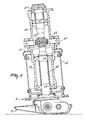
- the mowing unit of the mower-crusher or, when the crusher device is lacking, the mowing machine includes a cutter beam which, as has been stated in the foregoing, is constituted by the supporting beam 7, and superjacent mowing members 8, a carrier frame 31 ( Figures 1 and 3) and two connections between the cutter bar and the carrier frame, which connections in the embodiment shown in Figures 1 to 3 are effected via the two outermost mowing members, both of which are provided with a substantially drum-shaped crop guide.
- the manner in which the first connection is effected is shown in Figures 4 and 5, while the manner in which the second connection is effected is shown in Figure 6.
- connection between the supporting beam 7 and the carrier frame 31 includes a resilient element 32 which is designed here as a metal plate which near its upper edge is connected to the carrier frame 31 by means of bolts 33 and a connection plate member 34, and near its lower edge to a supporting member 36 by means of the bolts 35.
- the resilient element 32 extends in a plane located in the direction of operative travel.
- the supporting member 36 is bearing-supported in the relevant mowing member 8 by means of bearings 37.
- the resilient element 32 is located partly within the drum-shaped crop guide 10 arranged on the mowing member 8.
- connection plate members 38 are bolted to the supporting member 36 by means of the bolts 35; these connection plate members themselves are bolted by means of bolts 39 to a cover 40 for the drum-shaped crop guide 10.
- the cover 40 has a central aperture 41, through which the resilient element 32 extends.
- a flexible sleeve 42 extends between the cover 40 and the carrier frame 31.
- the resilient element 32 and its connection means 33, 34 to the carrier frame 31 extend within this sleeve 42.
- the resilient element 32 allows of both a slight bending and a slight shift of the supporting beam 7 relative to the carrier frame 31 in a vertical plane transversely to the direction of operative travel.
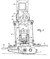
- connection between the supporting beam 7 and the carrier frame 31 includes a pivot 43 whose pivot shaft extends horizontally in the direction of operative travel.
- a pivotal member 44 is pivotable about the pivot shaft relative to a member 45 which is rigidly connected to the carrier frame 31.
- the drive shaft for the mowing members 8 in the supporting beam 7 extends through the member 45 and the pivotal member 44.
- the upper portion 46 of the drive shaft is bearing-supported in the member 45 by means of bearings 47.
- the lower portion 48 of the drive shaft is bearing-supported in the pivotal member 44 by means of bearings 49.
- the upper portion 46 of the drive shaft is connected to the lower portion 48 thereof by means of a flexible coupling 50, e.g.
- a chain coupling or a universal joint which is arranged in the region of the shaft of the pivot 43.
- the pivotal member 44 is arranged partly within the drum-shaped crop guide 10 disposed on the relevant mowing member 8.
- a cover 51 is rigidly connected to the pivotal member, which cover is located over this drum-shaped crop guide and is tightly contiguous thereto.
- the invention as it has been described so far is not only suitable for use in a mowing machine or in a mower-crusher which, as is apparent from Figures 1 to 3, is moved by a tractor as a side-mounted machine but also in a front-mounted mower or front-mounted mower-crusher.
- the use in a front-mounted mowing machine is shown in Figure 7.
- the second connection ( Figure 7) between the supporting beam 7 and the carrier frame 31 extends via the gear box 52, while a second gear box 53 is arranged halfway in the carrier frame.
- the mowing members 8 are driven by a transmission system which extends from the power take-off shaft of the tractor via the gear box 53, one half of the carrier frame 31, the gear box 52, the member 45 and the pivotal member 44 to the relevant outermost mowing member and from there to the further mowing members 8.
- the resilient element 32 is included in the first connection between the carrier frame 31 and the supporting beam 7, while the second connection between the carrier frame 31 and the supporting beam 7 includes the pivot shaft 43 with the flexible coupling 50 in the drive shaft.
- Figure 8 shows a partial side view of a mower-crusher, wherein the first connection between the carrier frame 31 and the supporting beam 7 does not extend via the relevant outermost mowing member but via the crusher device of the mower-crusher, i.e. via the second frame 11 thereof.
- the resilient element is constituted by a spring steel plate 54 which has one end connected to the supporting beam 7 and the other end to the lower end of the second frame 11 of the crusher device.
- the second connection between the carrier frame 31 and the supporting beam 7 can extend again via the relevant outermost mowing members, as is shown e.g. in Figure 6 or in Figure 9 to be described hereinafter.
- Figures 9 to 11 show a further embodiment of a front-mounted mowing machine in accordance with the invention.
- the first connection between the carrier frame 31 and the supporting beam 7 is arranged outside the reach of the mowing members.
- This connection incorporates a vertically extending connecting beam 55 which at its upper end is rigidly connected to the carrier frame 31 and at its lower end to the supporting beam 7 via an intermediate plate member 56 and a resilient element 57.
- the resilient element 57 is constituted by a substantially horizontally extending plate-shaped connection member, e.g. a spring steel plate.
- the second connection between the carrier frame 31 and the supporting beam 7 can be designed as is shown in Figure 6; Figures 9 and 10 show, however, a different embodiment.
- the carrier frame 31 is connected pivotably to a sleeve-shaped member 58.
- this sleeve-shaped member 58 there are connected rigidly pivot pins 59, around which the fork-shaped end 60 of the carrier frame 31 can pivot.
- the sleeve-shaped member is connected rigidly to a transmission system box 61, from which the drive of the mowing members 8 is effected via the drive shaft supported in this sleeve-shaped member 58.
- the outermost mowing member, via which the remaining mowing members are driven, is provided again with a crop guide 10; the sleeve-shaped member 58 extends partly inside this crop guide and includes an edge section 62 which is tightly contiguous to the crop guide and covers same.
- the forces acting on the cutter bar during operation are transferred by the drive shaft extending through this second connection between the carrier frame 31 and the supporting beam 7 to the input shaft 63 of the transmission system in the transmission system box 61. These forces can be such that the drive shaft and, via its bearing, the sleeve-shaped member 58 and the transmission system box may be subjected to a slight displacement in a vertical plane perpendicular to the direction of operative travel.
- the input shaft 63 is here preferably driven by one or more belts 64, more specifically from a shaft 65 which is supported rigidly relative to the carrier frame 31.
- This shaft 65 itself is driven again by a power take-off shaft of the tractor via the gear box 66.
Landscapes
- Life Sciences & Earth Sciences (AREA)
- Environmental Sciences (AREA)
- Harvester Elements (AREA)
Applications Claiming Priority (3)
| Application Number | Priority Date | Filing Date | Title |
|---|---|---|---|
| NL8801039 | 1988-04-21 | ||
| NL8801039A NL8801039A (nl) | 1988-04-21 | 1988-04-21 | Maaimachine. |
| EP89201003A EP0338649B1 (fr) | 1988-04-21 | 1989-04-19 | Faucheuse |
Related Parent Applications (2)
| Application Number | Title | Priority Date | Filing Date |
|---|---|---|---|
| EP89201003A Division EP0338649B1 (fr) | 1988-04-21 | 1989-04-19 | Faucheuse |
| EP89201003.4 Division | 1989-04-19 |
Publications (2)
| Publication Number | Publication Date |
|---|---|
| EP0622009A1 true EP0622009A1 (fr) | 1994-11-02 |
| EP0622009B1 EP0622009B1 (fr) | 1999-10-13 |
Family
ID=19852180
Family Applications (2)
| Application Number | Title | Priority Date | Filing Date |
|---|---|---|---|
| EP94201496A Expired - Lifetime EP0622009B1 (fr) | 1988-04-21 | 1989-04-19 | Machine de fauchage |
| EP89201003A Expired - Lifetime EP0338649B1 (fr) | 1988-04-21 | 1989-04-19 | Faucheuse |
Family Applications After (1)
| Application Number | Title | Priority Date | Filing Date |
|---|---|---|---|
| EP89201003A Expired - Lifetime EP0338649B1 (fr) | 1988-04-21 | 1989-04-19 | Faucheuse |
Country Status (5)
| Country | Link |
|---|---|
| US (1) | US4951450A (fr) |
| EP (2) | EP0622009B1 (fr) |
| AU (1) | AU620392B2 (fr) |
| DE (2) | DE68920470T2 (fr) |
| NL (1) | NL8801039A (fr) |
Cited By (1)
| Publication number | Priority date | Publication date | Assignee | Title |
|---|---|---|---|---|
| EP1110443A1 (fr) * | 1999-12-24 | 2001-06-27 | Maasland N.V. | Faucheuse-conditionneuse |
Families Citing this family (9)
| Publication number | Priority date | Publication date | Assignee | Title |
|---|---|---|---|---|
| NL194714C (nl) * | 1989-04-03 | 2003-01-07 | Lely Nv C Van Der | Maaimachine. |
| DK26790A (da) * | 1990-02-01 | 1991-08-02 | Taarup As Maskinfab | Skaarlaegger |
| US5778647A (en) * | 1996-06-25 | 1998-07-14 | New Holland North America, Inc. | Disc mower conditioner |
| FR2759533B1 (fr) * | 1997-02-14 | 1999-04-23 | Kuhn Sa | Faucheuse comportant un dispositif empechant la transmission de tout ou partie des vibrations entre le mecanisme de coupe et la structure porteuse |
| DE10055052C1 (de) * | 2000-11-07 | 2002-06-06 | Ziegler Gmbh | An einem Schlepper anbringbares Mähwerk |
| US7117817B2 (en) | 2004-08-03 | 2006-10-10 | Troy Overstreet | Animal feed harvesting and dispensing system |
| DE102006059220A1 (de) * | 2006-12-13 | 2008-06-19 | Claas Saulgau Gmbh | Mähmaschine zur frontseitigen Anordnung an einem landwirtschaftlichen Fahrzeug |
| US7814736B2 (en) * | 2008-03-03 | 2010-10-19 | Cnh America Llc | One piece tall feed drum |
| RU2656059C2 (ru) * | 2016-08-25 | 2018-05-30 | Федеральное государственное бюджетное научное учреждение "Федеральный научный центр кормопроизводства и агроэкологии имени В.Р. Вильямса" | Ротационная косилка с кондиционером бильного типа |
Citations (5)
| Publication number | Priority date | Publication date | Assignee | Title |
|---|---|---|---|---|
| FR2171674A5 (fr) * | 1972-02-04 | 1973-09-21 | Reber Walter | |
| WO1981002966A1 (fr) * | 1980-04-22 | 1981-10-29 | Massey Ferguson Services Nv | Moissonneuse-conditionneuse |
| EP0068560A2 (fr) * | 1981-07-01 | 1983-01-05 | Multinorm B.V. | Faucheuse |
| EP0118952A1 (fr) * | 1983-03-04 | 1984-09-19 | Multinorm B.V. | Dispositif faucheur à entraînement perfectionné et/ou tambour séparateur de la récolte |
| EP0177091A1 (fr) * | 1984-09-26 | 1986-04-09 | C. van der Lely N.V. | Machine de fauchage |
Family Cites Families (14)
| Publication number | Priority date | Publication date | Assignee | Title |
|---|---|---|---|---|
| US3517491A (en) * | 1968-08-08 | 1970-06-30 | Sperry Rand Corp | Header suspension mounting for pull-type harvesters |
| GB1543324A (en) * | 1975-05-02 | 1979-04-04 | Clayson Nv | Resilient mounting of attachment for agricultural machinery |
| NL171955C (nl) * | 1978-05-26 | 1983-06-16 | Zweegers P | Maaimachine. |
| DE2839841C2 (de) * | 1978-09-13 | 1987-03-05 | Klöckner-Humboldt-Deutz AG Zweigniederlassung Fahr, 7702 Gottmadingen | Mähwerk |
| FR2496394A1 (fr) * | 1980-12-18 | 1982-06-25 | Kuhn Sa | Perfectionnement aux supports d'elements coupants des faucheuses rotatives |
| NL8400818A (nl) * | 1984-03-15 | 1985-10-01 | Lely Nv C Van Der | Maaimachine. |
| FR2562758B1 (fr) * | 1984-04-12 | 1988-05-20 | Kuhn Sa | Faucheuse |
| FR2572881B1 (fr) * | 1984-11-12 | 1989-04-21 | Kuhn Sa | Faucheuse comportant un chassis muni d'une structure intermediaire et de moyens destines a empecher l'accrochage de fourrage a la dite structure intermediaire. |
| FR2597293B1 (fr) * | 1986-04-17 | 1988-08-05 | Kuhn Sa | Faucheuse rotative avec barre de coupe et structure support. |
| FR2598058B1 (fr) * | 1986-05-02 | 1989-10-13 | Kuhn Sa | Faucheuse munie d'au moins un organe de coupe surmonte par un tambour rotatif |
| DE3619792A1 (de) * | 1986-06-18 | 1987-12-23 | Basf Ag | Photopolymerisierbare aufzeichnungsmaterialien sowie photoresistschichten und flachdruckplatten auf basis dieser aufzeichnungsmaterialien |
| NL8601703A (nl) * | 1986-06-30 | 1988-01-18 | Lely Nv C Van Der | Maaimachine. |
| NL8602866A (nl) * | 1986-11-12 | 1988-06-01 | Lely Nv C Van Der | Maaimachine. |
| NL8602865A (nl) * | 1986-11-12 | 1988-06-01 | Lely Nv C Van Der | Maaimachine. |
-
1988
- 1988-04-21 NL NL8801039A patent/NL8801039A/nl not_active Application Discontinuation
-
1989
- 1989-04-19 DE DE68920470T patent/DE68920470T2/de not_active Expired - Fee Related
- 1989-04-19 DE DE68929086T patent/DE68929086T2/de not_active Expired - Fee Related
- 1989-04-19 EP EP94201496A patent/EP0622009B1/fr not_active Expired - Lifetime
- 1989-04-19 AU AU33178/89A patent/AU620392B2/en not_active Ceased
- 1989-04-19 EP EP89201003A patent/EP0338649B1/fr not_active Expired - Lifetime
- 1989-04-20 US US07/340,774 patent/US4951450A/en not_active Expired - Lifetime
Patent Citations (5)
| Publication number | Priority date | Publication date | Assignee | Title |
|---|---|---|---|---|
| FR2171674A5 (fr) * | 1972-02-04 | 1973-09-21 | Reber Walter | |
| WO1981002966A1 (fr) * | 1980-04-22 | 1981-10-29 | Massey Ferguson Services Nv | Moissonneuse-conditionneuse |
| EP0068560A2 (fr) * | 1981-07-01 | 1983-01-05 | Multinorm B.V. | Faucheuse |
| EP0118952A1 (fr) * | 1983-03-04 | 1984-09-19 | Multinorm B.V. | Dispositif faucheur à entraînement perfectionné et/ou tambour séparateur de la récolte |
| EP0177091A1 (fr) * | 1984-09-26 | 1986-04-09 | C. van der Lely N.V. | Machine de fauchage |
Cited By (2)
| Publication number | Priority date | Publication date | Assignee | Title |
|---|---|---|---|---|
| EP1110443A1 (fr) * | 1999-12-24 | 2001-06-27 | Maasland N.V. | Faucheuse-conditionneuse |
| WO2001047343A1 (fr) * | 1999-12-24 | 2001-07-05 | Maasland N.V. | Faucheuse-conditionneuse |
Also Published As
| Publication number | Publication date |
|---|---|
| DE68929086T2 (de) | 2000-05-25 |
| AU620392B2 (en) | 1992-02-20 |
| EP0338649B1 (fr) | 1995-01-11 |
| AU3317889A (en) | 1989-10-26 |
| DE68929086D1 (de) | 1999-11-18 |
| EP0622009B1 (fr) | 1999-10-13 |
| DE68920470T2 (de) | 1995-08-31 |
| EP0338649A1 (fr) | 1989-10-25 |
| US4951450A (en) | 1990-08-28 |
| NL8801039A (nl) | 1989-11-16 |
| DE68920470D1 (de) | 1995-02-23 |
Similar Documents
| Publication | Publication Date | Title |
|---|---|---|
| US4177625A (en) | Pull-type agricultural machine | |
| EP1364569B1 (fr) | Tondeuse | |
| US3389540A (en) | Device for the lateral suspension of a mowing bar or the like from a tractor | |
| EP0844814B1 (fr) | Machine pour la fenaison | |
| US4135349A (en) | Crop shredder apparatus and adapter | |
| US4185445A (en) | Mowing machine | |
| US4187664A (en) | Agricultural machine structure | |
| EP0269166B1 (fr) | Faucheuse | |
| US4956965A (en) | Boom mower attachment for a tractor adjustable for cutting at either side thereof | |
| EP0267659B1 (fr) | Faucheuse | |
| US4694640A (en) | Mowing machine for cutting hay and cereal grass | |
| GB1593689A (en) | Crop harvesting machine having header suspension means | |
| EP0155063B1 (fr) | Faucheuse | |
| EP0622009A1 (fr) | Machine de fauchage | |
| EP0558437A1 (fr) | Faucheuse de végétaux | |
| EP0361573B1 (fr) | Faucheuse | |
| AU3143102A (en) | Haymaking machine, particularly a mower with a windrow grouping device | |
| EP0642731A1 (fr) | Faucheuse | |
| EP0772967A1 (fr) | Faucheuse-conditionneuse | |
| EP1616474B1 (fr) | Faucheuse tractée comprenant un châssis et deux dispositifs de fauchage | |
| EP3766327B1 (fr) | Outil de travail | |
| EP0970597B1 (fr) | Faucheuse-conditioneuse | |
| EP0507408A1 (fr) | Machine agricole | |
| EP0740898A2 (fr) | Appareil pour le traitement de végétaux avec cadre pliant | |
| EP4331338A1 (fr) | Dispositif de tonte de disques |
Legal Events
| Date | Code | Title | Description |
|---|---|---|---|
| PUAI | Public reference made under article 153(3) epc to a published international application that has entered the european phase |
Free format text: ORIGINAL CODE: 0009012 |
|
| AC | Divisional application: reference to earlier application |
Ref document number: 338649 Country of ref document: EP |
|
| AK | Designated contracting states |
Kind code of ref document: A1 Designated state(s): DE FR GB NL |
|
| 17P | Request for examination filed |
Effective date: 19950403 |
|
| 17Q | First examination report despatched |
Effective date: 19980223 |
|
| GRAG | Despatch of communication of intention to grant |
Free format text: ORIGINAL CODE: EPIDOS AGRA |
|
| GRAG | Despatch of communication of intention to grant |
Free format text: ORIGINAL CODE: EPIDOS AGRA |
|
| GRAH | Despatch of communication of intention to grant a patent |
Free format text: ORIGINAL CODE: EPIDOS IGRA |
|
| GRAH | Despatch of communication of intention to grant a patent |
Free format text: ORIGINAL CODE: EPIDOS IGRA |
|
| GRAA | (expected) grant |
Free format text: ORIGINAL CODE: 0009210 |
|
| AC | Divisional application: reference to earlier application |
Ref document number: 338649 Country of ref document: EP |
|
| AK | Designated contracting states |
Kind code of ref document: B1 Designated state(s): DE FR GB NL |
|
| REF | Corresponds to: |
Ref document number: 68929086 Country of ref document: DE Date of ref document: 19991118 |
|
| ET | Fr: translation filed | ||
| PLBE | No opposition filed within time limit |
Free format text: ORIGINAL CODE: 0009261 |
|
| STAA | Information on the status of an ep patent application or granted ep patent |
Free format text: STATUS: NO OPPOSITION FILED WITHIN TIME LIMIT |
|
| 26N | No opposition filed | ||
| REG | Reference to a national code |
Ref country code: GB Ref legal event code: IF02 |
|
| PGFP | Annual fee paid to national office [announced via postgrant information from national office to epo] |
Ref country code: NL Payment date: 20030403 Year of fee payment: 15 |
|
| PGFP | Annual fee paid to national office [announced via postgrant information from national office to epo] |
Ref country code: GB Payment date: 20030416 Year of fee payment: 15 |
|
| PGFP | Annual fee paid to national office [announced via postgrant information from national office to epo] |
Ref country code: FR Payment date: 20030418 Year of fee payment: 15 |
|
| PGFP | Annual fee paid to national office [announced via postgrant information from national office to epo] |
Ref country code: DE Payment date: 20030430 Year of fee payment: 15 |
|
| PG25 | Lapsed in a contracting state [announced via postgrant information from national office to epo] |
Ref country code: GB Free format text: LAPSE BECAUSE OF NON-PAYMENT OF DUE FEES Effective date: 20040419 |
|
| PG25 | Lapsed in a contracting state [announced via postgrant information from national office to epo] |
Ref country code: NL Free format text: LAPSE BECAUSE OF NON-PAYMENT OF DUE FEES Effective date: 20041101 |
|
| PG25 | Lapsed in a contracting state [announced via postgrant information from national office to epo] |
Ref country code: DE Free format text: LAPSE BECAUSE OF NON-PAYMENT OF DUE FEES Effective date: 20041103 |
|
| GBPC | Gb: european patent ceased through non-payment of renewal fee |
Effective date: 20040419 |
|
| PG25 | Lapsed in a contracting state [announced via postgrant information from national office to epo] |
Ref country code: FR Free format text: LAPSE BECAUSE OF NON-PAYMENT OF DUE FEES Effective date: 20041231 |
|
| NLV4 | Nl: lapsed or anulled due to non-payment of the annual fee |
Effective date: 20041101 |
|
| REG | Reference to a national code |
Ref country code: FR Ref legal event code: ST |