EP0622016A1 - Perfectionnement d'un dispositif d'irrigation controlée pour plantes - Google Patents
Perfectionnement d'un dispositif d'irrigation controlée pour plantes Download PDFInfo
- Publication number
- EP0622016A1 EP0622016A1 EP94830195A EP94830195A EP0622016A1 EP 0622016 A1 EP0622016 A1 EP 0622016A1 EP 94830195 A EP94830195 A EP 94830195A EP 94830195 A EP94830195 A EP 94830195A EP 0622016 A1 EP0622016 A1 EP 0622016A1
- Authority
- EP
- European Patent Office
- Prior art keywords
- bath
- water
- container
- chamber
- plants
- Prior art date
- Legal status (The legal status is an assumption and is not a legal conclusion. Google has not performed a legal analysis and makes no representation as to the accuracy of the status listed.)
- Granted
Links
- 230000002262 irrigation Effects 0.000 title claims description 14
- 238000003973 irrigation Methods 0.000 title claims description 13
- XLYOFNOQVPJJNP-UHFFFAOYSA-N water Substances O XLYOFNOQVPJJNP-UHFFFAOYSA-N 0.000 claims abstract description 89
- 230000001105 regulatory effect Effects 0.000 claims abstract description 8
- 239000012535 impurity Substances 0.000 claims abstract description 5
- 230000005484 gravity Effects 0.000 claims description 6
- 239000000463 material Substances 0.000 claims description 4
- 229910052751 metal Inorganic materials 0.000 claims description 3
- 239000002184 metal Substances 0.000 claims description 3
- 239000007787 solid Substances 0.000 claims description 3
- 230000000694 effects Effects 0.000 claims description 2
- 230000001747 exhibiting effect Effects 0.000 claims description 2
- OYPRJOBELJOOCE-UHFFFAOYSA-N Calcium Chemical compound [Ca] OYPRJOBELJOOCE-UHFFFAOYSA-N 0.000 description 1
- 230000015572 biosynthetic process Effects 0.000 description 1
- 230000000903 blocking effect Effects 0.000 description 1
- 229910052791 calcium Inorganic materials 0.000 description 1
- 239000011575 calcium Substances 0.000 description 1
- 230000001419 dependent effect Effects 0.000 description 1
- 230000005611 electricity Effects 0.000 description 1
- 150000003839 salts Chemical class 0.000 description 1
Images


Classifications
-
- A—HUMAN NECESSITIES
- A01—AGRICULTURE; FORESTRY; ANIMAL HUSBANDRY; HUNTING; TRAPPING; FISHING
- A01G—HORTICULTURE; CULTIVATION OF VEGETABLES, FLOWERS, RICE, FRUIT, VINES, HOPS OR SEAWEED; FORESTRY; WATERING
- A01G27/00—Self-acting watering devices, e.g. for flower-pots
- A01G27/001—Self-acting watering devices, e.g. for flower-pots with intermittent watering means
Definitions
- the invention of the disclosure has a particular advantage in that it has no need of being attached to an electricity supply.
- Most of the examples in the prior art are electronic devices, essentially constituted by a electronic programmer connected to a running water supply through an open tap and having at its output a series of hoses arranged such as to reach the plants which have to be watered.
- the programmer establishes sets the watering modalities by programming a timer (set by a user) and acts on a valve connected to the tap and regulating the flow of water from the supply to the hoses.
- the user acting on a series of buttons and/or knobs provided on the programmer, has only to select the irrigation program he or she wants, and the program does the rest: watering time, duration of watering operation, day of watering and so on.
- a further drawback is that the tap has to be left open, and if, during the user's absence, the device should become faulty, there might ensue a constant and very damaging flow of water into the room housing the device.
- a still further drawback is the high cost of these devices, in relation to their usefulness, which after all is usually only on the occasions when the user leaves his or her house for a longish period of time.
- patent IT 1,234,704 which comprises a water container and distributor provided at its base with a plurality of outlet holes for the water and an open bath to receive said water.
- the bath is housed internally of the container and is pivoted on the container at a horizontal axis corrisponding to its centre of gravity (calculated when the bath is full).
- Valve means are also provided (constituted by a tap) which act on a supply pipeline of water to the bath, varying the water supply to the bath.
- the device further comprises a counterweight to maintain the bath in a water-receiving position, and to bring the bath back into the same position after it has emptied itself into the container by rotating on its axis.
- the principal aim of the present invention is to obviate the above-described drawbacks by providing an irrigation device comprising a bath for controlled distribution of water over a length of time, like to the above-described patent filed by the same applicant, and further provided with means. for erogating water from the tank which, apart from their primary function, also serve to prevent any blocking of the tap due to impurities in the water.
- the invention therefore provides a reliable irrigation device that has no need of electric or water supplies, and which supplies water to the plants notwithstanding any impurities in the water.
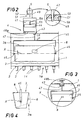
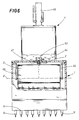
- the device principally comprises two elements: a container and distributor 1 of water and at least one open-topped bath 3 for receiving the water, which bath 3 is housed internally of the container 1 and pivoted to it.
- the container 1 is box-shaped and affords, on its base 1a, a plurality of water outlet holes 2, while the bath 3 has a truncopyramidal shape and is arranged internally of the container 1 with its open side 3a (being the larger base of the truncopyramid) upturned and opposite to the base container 1a.
- the bath 3 is pivoted, as will be described in more detail hereinbelow, on the container 1 on its horizontal centre of gravity, denoted by X and calculated to correspond to a point whereat the water level is just below the rim of the bath 3.
- a water supply pipe 5 preferably connected up to a tank 12 or in any case to a low-pressure water source.
- the water is supplied by a portable tank 12, provided with a handle 15 and positioned above the water outlet.
- the water delivery regulators comprise at least one chamber 41 having a horizontal section S which in the illustrated embodiment is constant, and is superiorly associated to the container 1 and provided superiorly with an inlet opening 42 connected to the water supply pipe 5, and inferiorly with an outlet opening 4 into the bath 3.
- the chamber 41 further exhibits a floating piston 44 having a slightly smaller surface than the section S of the chamber 41.
- the floating piston 44 is vertically slidable internally to the chamber 41 and can be positioned at different heights between the inlet opening 42 and the outlet opening 43, in order to control variations in the water head and thus water delivery from the outlet opening 43.
- the chamber 41 is provided with a stiffened pipe end 5a corresponding to a free end of the water supply pipe 5, (the pipe end 5a can even be constituted by a second pipe, stiffer than the original water supply pipe 5).
- the pipe end 5a has its free end turned downwards, constituting a vertical stop to the thrust developing from the volume of water contained in the chamber on the floating piston 44.
- means for fixing the pipe end 5a At or near the inlet opening 42 of the chamber 41 are located means for fixing the pipe end 5a at different heights corresponding to any desired floating piston 44 position.
- the inset of figure 2 shows a possible embodiment of the means for fixing the pipe end 5a, obtained by sliding said pipe end 5a through a like-shaped seating 50, a sufficient friction coefficient being thus obtained to permit of manually positioning the pipe 5a, and consequently the floating piston 44, at a desired height while at the same time not causing the pipe end 5a to be unwontedly moved due to the force exerted on it by the water acting inferiorly on the floating piston 44.
- the water flows into the chamber 41 through the pipe end 5a up until the floating piston 44, pushed upwards by the water, comes into contact with the free end 53 of the pipe end 5a, which obstructs it and prevents water exit up until the water level falls below the height corresponding to the contact between the floating piston 44 and the free end 53 of the pipe end 5a.
- a striker element 55 is advantageously provided at the contact point between the pipe end 5a and the free end 53: said striker element 55 is made in an easily elastically deformable material, such as to obtain a greater adhesion of the same to the edges of the free end 53 and better prevent water passage.
- a outer cover 51 is provided at the point where the pipe 5a is fixed, which cover 51 externally exhibits a graduated scale 49 having an indicator 52 solid to the pipe end 5a and indicating the different heights and thus the different pressures at which the water exits from the outlet opening 43.
- the bath 3 is associated to the container 1 at the outlet opening 43 of the chamber 41 by means of a fork 45.
- the fork 45 exhibits support points 46 supporting the bath 3 at axis X and a vertical rod 47 having a smaller section than the aperture of outlet opening 43, being slidable inside the latter and superiorly associated to elastic means 48 providing vertical and opposite elastic reaction R to the weight force P exerted downwards by the bath 3 when full.
- the bath 3 as in the applicant's previous patent IT 1,234,704, receives the water while remaining stable and in its original position until the water reaches up to just below its rim. At this point the centre of gravity axis X is just operative, but once the above-mentioned level is surpassed, the natural centre of gravity of the bath 3 moves, causing the bath 3 to rotate on its axis S and its side 3a to move into a position where it is practically facing the holes 2 (see figure 4, broken lines), whereat the water is poured into the container 1. Then the empty bath 3 returns into its original position, helped by a plate 8 acting as counterweight. The water channels into the holes 2 and thus into the pipes 14, whereby it is conducted to the vases 13 containing the plants to be watered.
- the rod 47 (preferably made of metal or a rigid plastic material), which consequently performs a vertical sliding movement internally of the outlet opening 43 of the chamber 41, removes residues from the outlet opening 43 and guarantees a constant water flow.
- the device is programmed by varying the water delivery: this is done by altering the floating piston 44 level, using the graduated scale as a measure. By increasing the water head there will be a greater water outlet through the outlet opening 43: once the water has flowed out of the outlet opening 43, it is collected in the bath 3 and distributed as described above.
- the volume of the bath 3 can be changed, or a second bath 3 might be provided, having a greater volume than the first and being directly pivoted on the container 1 downstream of the bath 3, so as to empty at longer time intervals.
- the elastic means 48 might be a flexible sheet of metal 48a, as in figure 2, associated at one of its ends to a fixed point in the chamber 41 or the container 1 and fixed at another end to the rod 47.
- the 48 comprises a spring 48b acting between the fork 45 and a fixed point on the chamber 41 or the container 1.
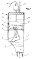
- the rod 47 is supported by a support 61 pivoted on an axis Z solid to the container 1 or the chamber 41.
- the support 61 exhibits a striker portion 62, camshaped in the figures, for the bath 3, which interacts with the bath 3 when the latter is rotated.
- the support 61 is mobile between a first position (shown in figure 8), whereat it is subject to the force of its own weight and the rod 47 is external to the outlet opening 43, and a second position (shown in figures 6 and 7 and in the enlarged detail of figure 8) in which it is subject to a thrust by the rotated bath 3 and the rod 47 is at least partially inserted in the outlet opening 43.
- the rod 47 is set in alternating motion at fillings and emptyings of the bath 3.
- Figure 8 shows how the outlet opening 43 can be provided with a circular opening exhibiting a slot 43a.
- a seating 64 might be provided in the chamber 41 at the outlet opening 43 to receive (by effect of force of gravity) a sphere of heavier material than water and having a diameter which is superior to that of the circular portion of the outlet opening 43. In this way, water contained in the chamber 41 can flow out through the slot 43a, falling into the underlying bath 3.
- the sphere 63 is displaced allows a greater flow of water to pass, in order to add the action of the rod 47 to the drawing action of the greater-than normal flow of water through the slot 43a.
- the floow of water is indicated by un-numbered arrows or drops.
- the container 1 can be provided with a plurality of superiorly-open cells 11 which subdivide the inferior portion by a height H not inferior to that reached by a quantity of water equal to the volume of the bath 3 (and in any case by a height such as to permit the emptying and filling movements of the bath 3).
- the cells 11 subdivide the volume of water into corresponding smaller volume, each of which is destined to serve vases 13 joined up to the holes 2 by hoses 14.
- FIG 5 such a subdivision is illustrated, where, in an embodiment which is different from that of the other figures, a container 1 not provided with the bath 3 is sectioned horizontally at a greater height than that reached by the cells 11.
- the cells 11 illustrated in figure 5 have different volumes according to the different quantities of water to be provided, but could have the same volume, naturally if it were necessary to feed equal quantities of water to different plants.
Landscapes
- Engineering & Computer Science (AREA)
- Water Supply & Treatment (AREA)
- Life Sciences & Earth Sciences (AREA)
- Environmental Sciences (AREA)
- Devices For Medical Bathing And Washing (AREA)
- Feeding, Discharge, Calcimining, Fusing, And Gas-Generation Devices (AREA)
- Control Of Non-Electrical Variables (AREA)
- Float Valves (AREA)
- Devices For Dispensing Beverages (AREA)
Applications Claiming Priority (2)
| Application Number | Priority Date | Filing Date | Title |
|---|---|---|---|
| IT93BO000093U IT232895Y1 (it) | 1993-04-27 | 1993-04-27 | Perfezionamento di dispositivo per l'irrigazione controllata di piante |
| ITBO930093U | 1993-04-27 |
Publications (2)
| Publication Number | Publication Date |
|---|---|
| EP0622016A1 true EP0622016A1 (fr) | 1994-11-02 |
| EP0622016B1 EP0622016B1 (fr) | 1996-03-06 |
Family
ID=11338795
Family Applications (1)
| Application Number | Title | Priority Date | Filing Date |
|---|---|---|---|
| EP94830195A Expired - Lifetime EP0622016B1 (fr) | 1993-04-27 | 1994-04-26 | Perfectionnement d'un dispositif d'irrigation controlée pour plantes |
Country Status (9)
| Country | Link |
|---|---|
| US (1) | US5415347A (fr) |
| EP (1) | EP0622016B1 (fr) |
| CA (1) | CA2122078A1 (fr) |
| DE (1) | DE69400080T2 (fr) |
| ES (1) | ES2086991T3 (fr) |
| GR (1) | GR3019695T3 (fr) |
| IT (1) | IT232895Y1 (fr) |
| PL (1) | PL171985B1 (fr) |
| SI (1) | SI0622016T1 (fr) |
Cited By (2)
| Publication number | Priority date | Publication date | Assignee | Title |
|---|---|---|---|---|
| EP0700633A1 (fr) * | 1994-08-08 | 1996-03-13 | Kabushiki Kaisha Yamazen Kanagata | Dispositif pour arroser des pots de fleurs |
| US5725156A (en) * | 1995-09-18 | 1998-03-10 | Park; Hong Ku | Moisture feeding apparatus for plants |
Families Citing this family (4)
| Publication number | Priority date | Publication date | Assignee | Title |
|---|---|---|---|---|
| GB2368767B (en) * | 2000-11-13 | 2004-01-07 | Wen-Chi Lai | Bean sprout culture box with a sprinkling device |
| US7730665B2 (en) * | 2008-04-02 | 2010-06-08 | Tri Tran | Automatic plant and bird waterer |
| US8166704B1 (en) | 2009-04-30 | 2012-05-01 | Sydlowski Russell L | Plant watering device |
| PL238890B1 (pl) * | 2018-11-29 | 2021-10-18 | Univ Warminsko Mazurski W Olsztynie | Zautomatyzowana platforma podlewająca |
Citations (4)
| Publication number | Priority date | Publication date | Assignee | Title |
|---|---|---|---|---|
| FR2156477A1 (fr) * | 1971-10-21 | 1973-06-01 | Rodriguez Jean | |
| US4042150A (en) * | 1976-03-31 | 1977-08-16 | Hans Walter Roos | Water gravity plant feeder |
| US4157770A (en) * | 1977-08-11 | 1979-06-12 | Roos Hans W | Water gravity plant feeder |
| EP0394199A1 (fr) * | 1989-01-25 | 1990-10-24 | Piero Sommariva | Dispositif d'irrigation automatique de cultures de plantes |
Family Cites Families (8)
| Publication number | Priority date | Publication date | Assignee | Title |
|---|---|---|---|---|
| US1670164A (en) * | 1924-07-11 | 1928-05-15 | Edward G Pfahl | Apparatus for feeding and distributing vinegar stock |
| AT201922B (de) * | 1957-10-31 | 1959-02-10 | Johann Fuehrer | Bewässerungsvorrichtung für Blumentöpfe od. dgl. |
| US3168224A (en) * | 1963-08-12 | 1965-02-02 | Rios Armando | Drip feed device |
| US3542069A (en) * | 1968-05-23 | 1970-11-24 | Napolean E Ollison | Apparatus for automatically feeding water at spaced time intervals |
| US3900134A (en) * | 1973-11-26 | 1975-08-19 | Harold B Larson | Automatic plant watering apparatus |
| ES425543A1 (es) * | 1974-04-20 | 1976-06-16 | Martinez Martinez | Sistema automatico perfeccionado de riego para macetas, jardineras y plantas en el suelo. |
| SU940708A1 (ru) * | 1980-04-24 | 1982-07-07 | Войсковая часть 27177-В | Установка дл автоматического полива растений |
| US4676023A (en) * | 1985-02-06 | 1987-06-30 | Kei Mori | Cultivation device by use of water-and-air mixture |
-
1993
- 1993-04-27 IT IT93BO000093U patent/IT232895Y1/it active IP Right Grant
-
1994
- 1994-04-25 CA CA002122078A patent/CA2122078A1/fr not_active Abandoned
- 1994-04-25 US US08/233,045 patent/US5415347A/en not_active Expired - Lifetime
- 1994-04-26 ES ES94830195T patent/ES2086991T3/es not_active Expired - Lifetime
- 1994-04-26 EP EP94830195A patent/EP0622016B1/fr not_active Expired - Lifetime
- 1994-04-26 PL PL94303184A patent/PL171985B1/pl unknown
- 1994-04-26 DE DE69400080T patent/DE69400080T2/de not_active Expired - Fee Related
- 1994-04-26 SI SI9430001T patent/SI0622016T1/xx unknown
-
1996
- 1996-04-22 GR GR960401074T patent/GR3019695T3/el unknown
Patent Citations (4)
| Publication number | Priority date | Publication date | Assignee | Title |
|---|---|---|---|---|
| FR2156477A1 (fr) * | 1971-10-21 | 1973-06-01 | Rodriguez Jean | |
| US4042150A (en) * | 1976-03-31 | 1977-08-16 | Hans Walter Roos | Water gravity plant feeder |
| US4157770A (en) * | 1977-08-11 | 1979-06-12 | Roos Hans W | Water gravity plant feeder |
| EP0394199A1 (fr) * | 1989-01-25 | 1990-10-24 | Piero Sommariva | Dispositif d'irrigation automatique de cultures de plantes |
Cited By (2)
| Publication number | Priority date | Publication date | Assignee | Title |
|---|---|---|---|---|
| EP0700633A1 (fr) * | 1994-08-08 | 1996-03-13 | Kabushiki Kaisha Yamazen Kanagata | Dispositif pour arroser des pots de fleurs |
| US5725156A (en) * | 1995-09-18 | 1998-03-10 | Park; Hong Ku | Moisture feeding apparatus for plants |
Also Published As
| Publication number | Publication date |
|---|---|
| ITBO930093U1 (it) | 1994-10-27 |
| US5415347A (en) | 1995-05-16 |
| SI0622016T1 (en) | 1997-10-31 |
| EP0622016B1 (fr) | 1996-03-06 |
| ITBO930093V0 (it) | 1993-04-27 |
| IT232895Y1 (it) | 2000-01-21 |
| GR3019695T3 (en) | 1996-07-31 |
| CA2122078A1 (fr) | 1994-10-28 |
| DE69400080T2 (de) | 1996-08-08 |
| DE69400080D1 (de) | 1996-04-11 |
| PL171985B1 (pl) | 1997-07-31 |
| ES2086991T3 (es) | 1996-07-01 |
Similar Documents
| Publication | Publication Date | Title |
|---|---|---|
| US5279071A (en) | Automatic tree and/or plant waterer | |
| US7222454B1 (en) | Apparatus and method for watering a houseplant | |
| US7730665B2 (en) | Automatic plant and bird waterer | |
| US5385590A (en) | Hydroponic planter | |
| US4138967A (en) | Water supply and control device | |
| US4527353A (en) | Irrigation/fertilization control and distribution system | |
| US4961285A (en) | Plant irrigation system | |
| US3900134A (en) | Automatic plant watering apparatus | |
| JPH0837963A (ja) | 自動液体配給装置 | |
| US5329729A (en) | Plant irrigation system | |
| EP0622016B1 (fr) | Perfectionnement d'un dispositif d'irrigation controlée pour plantes | |
| US4546571A (en) | Plant watering apparatus | |
| US5493811A (en) | Plant watering method and apparatus | |
| US4157770A (en) | Water gravity plant feeder | |
| US4006843A (en) | Apparatus and method of watering objects | |
| US20020116870A1 (en) | Automatic houseplant watering apparatus for homes and offices | |
| WO1994004971A1 (fr) | Dispositif pour controler le niveau d'un liquide | |
| US4085546A (en) | Liquid supply system for gardens | |
| US7086199B2 (en) | Automatic liquid delivery system with time-delay release mechanism | |
| US5743290A (en) | Multi-purpose automatic filling and leveling liquid basin with liquid transfer | |
| GB2583975A (en) | Irrigation control system | |
| WO1998027803B1 (fr) | Dispositif d'arrosage automatique | |
| JP2001078595A (ja) | 植木鉢の自動給水装置及びその部品 | |
| US20040221817A1 (en) | Remote watering devices | |
| GB2357687A (en) | Plant watering and feeding system |
Legal Events
| Date | Code | Title | Description |
|---|---|---|---|
| PUAI | Public reference made under article 153(3) epc to a published international application that has entered the european phase |
Free format text: ORIGINAL CODE: 0009012 |
|
| AK | Designated contracting states |
Kind code of ref document: A1 Designated state(s): BE DE ES FR GB GR IT NL |
|
| 17P | Request for examination filed |
Effective date: 19941115 |
|
| 17Q | First examination report despatched |
Effective date: 19950518 |
|
| GRAA | (expected) grant |
Free format text: ORIGINAL CODE: 0009210 |
|
| AK | Designated contracting states |
Kind code of ref document: B1 Designated state(s): BE DE ES FR GB GR IT NL |
|
| AX | Request for extension of the european patent |
Free format text: SI PAYMENT 940511 |
|
| RAX | Requested extension states of the european patent have changed |
Free format text: SI PAYMENT 940511 |
|
| ITF | It: translation for a ep patent filed | ||
| REF | Corresponds to: |
Ref document number: 69400080 Country of ref document: DE Date of ref document: 19960411 |
|
| ET | Fr: translation filed | ||
| REG | Reference to a national code |
Ref country code: GR Ref legal event code: FG4A Free format text: 3019695 |
|
| REG | Reference to a national code |
Ref country code: ES Ref legal event code: FG2A Ref document number: 2086991 Country of ref document: ES Kind code of ref document: T3 |
|
| PLBE | No opposition filed within time limit |
Free format text: ORIGINAL CODE: 0009261 |
|
| STAA | Information on the status of an ep patent application or granted ep patent |
Free format text: STATUS: NO OPPOSITION FILED WITHIN TIME LIMIT |
|
| 26N | No opposition filed | ||
| PGFP | Annual fee paid to national office [announced via postgrant information from national office to epo] |
Ref country code: GR Payment date: 20000417 Year of fee payment: 7 |
|
| PGFP | Annual fee paid to national office [announced via postgrant information from national office to epo] |
Ref country code: ES Payment date: 20000419 Year of fee payment: 7 |
|
| PGFP | Annual fee paid to national office [announced via postgrant information from national office to epo] |
Ref country code: NL Payment date: 20000428 Year of fee payment: 7 |
|
| PGFP | Annual fee paid to national office [announced via postgrant information from national office to epo] |
Ref country code: BE Payment date: 20000622 Year of fee payment: 7 |
|
| PG25 | Lapsed in a contracting state [announced via postgrant information from national office to epo] |
Ref country code: ES Free format text: LAPSE BECAUSE OF NON-PAYMENT OF DUE FEES Effective date: 20010427 |
|
| PG25 | Lapsed in a contracting state [announced via postgrant information from national office to epo] |
Ref country code: GR Free format text: LAPSE BECAUSE OF NON-PAYMENT OF DUE FEES Effective date: 20010430 Ref country code: BE Free format text: LAPSE BECAUSE OF NON-PAYMENT OF DUE FEES Effective date: 20010430 |
|
| BERE | Be: lapsed |
Owner name: G.F. S.R.L. Effective date: 20010430 |
|
| PG25 | Lapsed in a contracting state [announced via postgrant information from national office to epo] |
Ref country code: NL Free format text: LAPSE BECAUSE OF NON-PAYMENT OF DUE FEES Effective date: 20011101 |
|
| REG | Reference to a national code |
Ref country code: GB Ref legal event code: IF02 |
|
| NLV4 | Nl: lapsed or anulled due to non-payment of the annual fee |
Effective date: 20011101 |
|
| REG | Reference to a national code |
Ref country code: ES Ref legal event code: FD2A Effective date: 20030303 |
|
| PGFP | Annual fee paid to national office [announced via postgrant information from national office to epo] |
Ref country code: GB Payment date: 20030423 Year of fee payment: 10 |
|
| PGFP | Annual fee paid to national office [announced via postgrant information from national office to epo] |
Ref country code: FR Payment date: 20030425 Year of fee payment: 10 |
|
| PGFP | Annual fee paid to national office [announced via postgrant information from national office to epo] |
Ref country code: DE Payment date: 20030508 Year of fee payment: 10 |
|
| PG25 | Lapsed in a contracting state [announced via postgrant information from national office to epo] |
Ref country code: GB Free format text: LAPSE BECAUSE OF NON-PAYMENT OF DUE FEES Effective date: 20040426 |
|
| PG25 | Lapsed in a contracting state [announced via postgrant information from national office to epo] |
Ref country code: DE Free format text: LAPSE BECAUSE OF NON-PAYMENT OF DUE FEES Effective date: 20041103 |
|
| GBPC | Gb: european patent ceased through non-payment of renewal fee |
Effective date: 20040426 |
|
| PG25 | Lapsed in a contracting state [announced via postgrant information from national office to epo] |
Ref country code: FR Free format text: LAPSE BECAUSE OF NON-PAYMENT OF DUE FEES Effective date: 20041231 |
|
| REG | Reference to a national code |
Ref country code: FR Ref legal event code: ST |
|
| PGFP | Annual fee paid to national office [announced via postgrant information from national office to epo] |
Ref country code: IT Payment date: 20070515 Year of fee payment: 14 |
|
| PG25 | Lapsed in a contracting state [announced via postgrant information from national office to epo] |
Ref country code: IT Free format text: LAPSE BECAUSE OF NON-PAYMENT OF DUE FEES Effective date: 20080426 |