EP0622295A1 - Lageregelung eines drallstabilisierten Raumfahrzeuges - Google Patents
Lageregelung eines drallstabilisierten Raumfahrzeuges Download PDFInfo
- Publication number
- EP0622295A1 EP0622295A1 EP94302931A EP94302931A EP0622295A1 EP 0622295 A1 EP0622295 A1 EP 0622295A1 EP 94302931 A EP94302931 A EP 94302931A EP 94302931 A EP94302931 A EP 94302931A EP 0622295 A1 EP0622295 A1 EP 0622295A1
- Authority
- EP
- European Patent Office
- Prior art keywords
- spacecraft
- axis
- control moment
- gimbal
- attitude
- Prior art date
- Legal status (The legal status is an assumption and is not a legal conclusion. Google has not performed a legal analysis and makes no representation as to the accuracy of the status listed.)
- Withdrawn
Links
- 238000009987 spinning Methods 0.000 title claims abstract description 7
- 230000008859 change Effects 0.000 claims abstract description 6
- 238000000034 method Methods 0.000 claims description 9
- 230000014509 gene expression Effects 0.000 description 6
- 230000008901 benefit Effects 0.000 description 2
- 238000013016 damping Methods 0.000 description 2
- 238000010586 diagram Methods 0.000 description 2
- 239000000446 fuel Substances 0.000 description 1
- 230000004048 modification Effects 0.000 description 1
- 238000012986 modification Methods 0.000 description 1
- 230000010355 oscillation Effects 0.000 description 1
- 230000008569 process Effects 0.000 description 1
- 239000003380 propellant Substances 0.000 description 1
- 230000005855 radiation Effects 0.000 description 1
- 230000004044 response Effects 0.000 description 1
Images

Classifications
-
- B—PERFORMING OPERATIONS; TRANSPORTING
- B64—AIRCRAFT; AVIATION; COSMONAUTICS
- B64G—COSMONAUTICS; VEHICLES OR EQUIPMENT THEREFOR
- B64G1/00—Cosmonautic vehicles
- B64G1/22—Parts of, or equipment specially adapted for fitting in or to, cosmonautic vehicles
- B64G1/24—Guiding or controlling apparatus, e.g. for attitude control
- B64G1/28—Guiding or controlling apparatus, e.g. for attitude control using inertia or gyro effect
- B64G1/281—Spin-stabilised spacecraft
-
- B—PERFORMING OPERATIONS; TRANSPORTING
- B64—AIRCRAFT; AVIATION; COSMONAUTICS
- B64G—COSMONAUTICS; VEHICLES OR EQUIPMENT THEREFOR
- B64G1/00—Cosmonautic vehicles
- B64G1/22—Parts of, or equipment specially adapted for fitting in or to, cosmonautic vehicles
- B64G1/24—Guiding or controlling apparatus, e.g. for attitude control
- B64G1/244—Spacecraft control systems
-
- B—PERFORMING OPERATIONS; TRANSPORTING
- B64—AIRCRAFT; AVIATION; COSMONAUTICS
- B64G—COSMONAUTICS; VEHICLES OR EQUIPMENT THEREFOR
- B64G1/00—Cosmonautic vehicles
- B64G1/22—Parts of, or equipment specially adapted for fitting in or to, cosmonautic vehicles
- B64G1/24—Guiding or controlling apparatus, e.g. for attitude control
- B64G1/28—Guiding or controlling apparatus, e.g. for attitude control using inertia or gyro effect
- B64G1/285—Guiding or controlling apparatus, e.g. for attitude control using inertia or gyro effect using momentum wheels
Definitions
- This invention broadly relates to positioning of spacecraft and more particularly to attitude control.
- Attitude control of spin stabilized spacecraft has traditionally been accomplished by pulsed thrusters which provide spin phased moments. This works well when the operational spin axis is normal to the orbit plane. The payloads in some spacecraft, however, require a nadir pointing spin axis.
- momentum cancelling wheels hard mounted to the spacecraft are used to create a zero momentum system.
- reaction control thrusters are used to create the starting and stopping moments. If solar radiation pressure creates undesired external moments, thrusters are also used to cancel such moments.
- reaction control thrusters While reaction control thrusters are necessary, it would be desirable to use them as little as possible. There is a limited amount of propellant available to fire the thrusters. The more that the thrusters must be fired, the less fuel available for later maneuvers. Further, there are inherent uncertainties involving a thruster on-time and sophisticated methods are required in order to compensate for these uncertainties.
- the present invention relates to an apparatus and method for attitude control of a spinning spacecraft whose spin axis is substantially in the plane of the orbit without the use of reaction control thrusters.
- the attitude control system of the present invention includes a two-axis gimbal mounted to the central body of a spacecraft.
- the spacecraft has a center of momentum, CM, which acts as the origin for principal body axes x, y, and z, each of which is at a right angle to the other two.
- the spacecraft spins about the z-axis.
- the gimbal has a first portion pivoting about the x-axis and a second portion pivoting about the y-axis.
- a momentum wheel is secured to the gimbal.
- the control system includes at least two actuators, a first actuator disposed between the outer surface of the spacecraft and the first portion to apply a first control moment about the x-axis.
- a second actuator is disposed between the outer surface and the second portion to apply a second control moment about the y-axis. Together, these control moments are used to control the attitude of the satellite.
- the actuators are electromagnetic force generators.
- a satellite provided with such an attitude control system has a gyroscope to sense the attitude state of the spacecraft.
- a control processor receives this information and computes a control moment signal.
- This control moment signal is applied to the actuators to generate a force within them. This force causes the gimballed momentum wheel to react against the central body of the spacecraft and results in a selected control moment being applied about the x-axis and the y-axis to change the attitude state of the spacecraft.
- a feedforward input signal and a feedback input signal are both computed in order to damp the excited nutation which results from the starts and stops of maneuvers.
- the attitude state may be changed using the present invention so that the satellite may center on any point of the planet which it circles.
- a radio command system receiver may be used to receive commands to change the attitude state, the commands being sent to the processor for computation.
- attitude control system 22 illustrated in Figure 1.
- Spacecraft 20 is intended to have a spin axis substantially within the plane of the orbit, whose attitude may be controlled without the use of reaction control thrusters.
- the spacecraft 20, which is generally used in applications requiring selective centering on any point of the planet which it circles, must be able to have a spin axis which is not completely within the plane of the orbit. For example, in order to center on a point between the equator and a pole of the earth, a spacecraft in geosynchronous orbit about the earth must be able to rotate through an angle of approximately 8.7 degrees.
- Spacecraft 20 has a center of momentum, CM, which acts as the origin for principal body axes x, y, and z, each of which is at a right angle to the other two.
- System 22 comprises a two-axis gimbal 24 on which a momentum wheel 26 is mounted via a shaft 28. Shaft 28 extends outwardly from central body 21.
- Gimbal 24 includes an outer annular ring portion 30 secured about a pivot 32 extending along the y-axis and an inner annular ring portion 34 secured about a pivot 35 extending along the x-axis.
- Gimbal 24 is mounted to central body 21 via supports 36, which secure pivot 32 to an outer surface 37 of the spacecraft. Pivot 35 is secured between outer portion 30 and inner portion 34.
- Shaft 28 extends outwardly from a central portion 38 of inner portion 34.
- Control moments which affect the attitude of spacecraft 20 are selectively applied by actuators 40 and 42, respectively.
- Actuator 40 is secured to outer surface 37 and positioned to apply a selected control moment about the x-axis via its contact with inner ring 34 while actuator 42 is secured to outer surface 37 and positioned to apply a moment about the y-axis via its contact with outer ring 30. It is preferred that actuator 40 be located along the y-axis and actuator 42 located along the x-axis to balance the application of the applied control monents and avoid the undesirable application of unwanted secondary moments.
- Actuators 40 and 42 may be composed of any number of devices including electromagnetic force generators such as the voice coils of loudspeakers.
- a selected force developed by actuator 40 exerted on central body 21, causing it to react against momentum wheel 26, creates a moment L x about the x-axis of spacecraft 20.
- a force developed by actuator 42 exerted on central body 21 creates a moment L y about the y-axis of the spacecraft.
- the moments of inertia about the principal axes x, y, and z of spacecraft 20 are I x , I y , and I z respectively.
- Spacecraft 20 spins about its z-axis with an angular rate ⁇ z radians per second. If the spacecraft is to orbit a planet at a fixed angular orbital rate of n radians per second with no wobble, the transverse angular velocity ⁇ ⁇ T of the spacecraft must be a constant n radians per second in inertial coordinates.
- ⁇ x is the angular rate about the x--axis and ⁇ y is the angular rate about the y-axis.
- t represents time.
- ⁇ ⁇ x -n ⁇ z sin ⁇ z t
- ⁇ ⁇ y -n ⁇ z cos ⁇ z t.
- Equation (10) has two terms, the first of which counterspins and the second of which forward spins.
- the first term is thus fixed in inertial space, and precesses the body at the orbital rate.
- the second term forward rotates in inertial space at twice ⁇ z and keeps the precession steady in the presence of asymmetry.
- System 22 is designed to provided these two components as required via the positioning and use of actuators 40 and 42 in conjunction with the two-axis gimbal 24 on which momentum wheel 26 is mounted.
- the first term in equation (15) is consistent with the desired steady orbital rate precession, while the second term, which represents a forward rotation at twice the spin rate in inertial coordinates, is an undesired wobble. It occurs in a system having a prior art hard mounted momentum cancelling wheel. This wobble does not occur when using system 22.
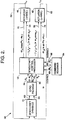
- the spacecraft control processor 52 computes control moments L x and L y .
- Feed-forward input signals 54 and 56 represented by equations (8) and (9) are inputted to actuators 40 and 42, respectively.
- the actuators respond and outputs 58 and 60 result in a change in spacecraft dynamics 61.
- Actuators 40 and 42 apply the indicated moments L x and L y by generating a force resulting in the reaction of central body 21 against the gimballed momentum wheel 26 as discussed above.
- a rate gyroscope sensor package 62 senses the actual pointing directions and angular rates 63 of spacecraft 20, which are then inputted into spacecraft control process 62.
- a radio command system receiver 64 receives the desired pointing directions ⁇ x and ⁇ y , and the desired angular rates.
- Spacecraft control processor 62 accepts the inputs 66 from gyroscope sensor package 62 and inputs 68 from receiver 64 and computes feed-forward input signals 54 and 56 and feedback input signals 66 and 68.
- Feedback input signals 70 and 72 are used to close the feedback loops for L x and L y .
- Feedback input signals to close the feedback loops for each selected control motion are present in a preferred embodiment because the starts and stops of maneuvers excite nutation which persist unless damped.
- Nutation damping via a transverse angle rate feedback is a convenient method of causing rapid decay of nutation. This feedback will also correct most calibration errors.
- gyroscope package 62 is essential.
- the feedback input signals represent the difference between the desired rate as shown in equations (2) and (3) respectively, and the actual angular rates measured by gyros 62. Thus, the unwanted components of angular rate are suppressed.
Landscapes
- Engineering & Computer Science (AREA)
- Remote Sensing (AREA)
- Chemical & Material Sciences (AREA)
- Combustion & Propulsion (AREA)
- Radar, Positioning & Navigation (AREA)
- Aviation & Aerospace Engineering (AREA)
- Automation & Control Theory (AREA)
- Control Of Position, Course, Altitude, Or Attitude Of Moving Bodies (AREA)
Applications Claiming Priority (2)
| Application Number | Priority Date | Filing Date | Title |
|---|---|---|---|
| US08/052,879 US5441222A (en) | 1993-04-26 | 1993-04-26 | Attitude control of spinning spacecraft |
| US52879 | 1998-04-01 |
Publications (1)
| Publication Number | Publication Date |
|---|---|
| EP0622295A1 true EP0622295A1 (de) | 1994-11-02 |
Family
ID=21980507
Family Applications (1)
| Application Number | Title | Priority Date | Filing Date |
|---|---|---|---|
| EP94302931A Withdrawn EP0622295A1 (de) | 1993-04-26 | 1994-04-25 | Lageregelung eines drallstabilisierten Raumfahrzeuges |
Country Status (3)
| Country | Link |
|---|---|
| US (1) | US5441222A (de) |
| EP (1) | EP0622295A1 (de) |
| JP (1) | JPH07137698A (de) |
Cited By (4)
| Publication number | Priority date | Publication date | Assignee | Title |
|---|---|---|---|---|
| DE19640277A1 (de) * | 1996-09-30 | 1997-03-20 | Geuer Mann Ernst | Maschine zur Erzeugung von Winkelbeschleunigungen, für Steuerzwecke durch das Wechselwirkungsprinzip |
| EP0788045A1 (de) * | 1996-02-05 | 1997-08-06 | HE HOLDINGS, INC. dba HUGHES ELECTRONICS | Sonne/Erde Ausrichtung ohne Triebwerke |
| FR2759974A1 (fr) * | 1997-02-21 | 1998-08-28 | Matra Marconi Space France | Procede et systeme integre d'actionneur inertiel et de senseur de vitesses angulaires d'un satellite |
| CN106240846A (zh) * | 2015-06-15 | 2016-12-21 | 波音公司 | 交通工具姿态控制 |
Families Citing this family (21)
| Publication number | Priority date | Publication date | Assignee | Title |
|---|---|---|---|---|
| US5820078A (en) * | 1996-09-27 | 1998-10-13 | Hughes Electronics Corporation | Control motion gyro with vibration isolation |
| US6068218A (en) * | 1997-05-14 | 2000-05-30 | Hughes Electronics Corporation | Agile, spinning spacecraft with sun-steerable solar cell array and method |
| US6032903A (en) * | 1998-02-12 | 2000-03-07 | Hughes Electronics Corporation | Cooperative control structures and methods for satellite spin axis control |
| US6138953A (en) * | 1998-03-02 | 2000-10-31 | Hughes Electronics Corporation | Slew rate direction determination for acquisition maneuvers using reaction wheels |
| US6039290A (en) * | 1998-03-16 | 2000-03-21 | Honeywell Inc. | Robust singularity avoidance in satellite attitude control |
| FR2786283B1 (fr) | 1998-11-19 | 2001-01-26 | Matra Marconi Space France | Procede et dispositif de pilotage de l'attitude d'un satellite |
| US6152402A (en) * | 1999-04-07 | 2000-11-28 | Hughes Electronics Corporation | Dual spin zero momentum satellite system |
| US6196502B1 (en) * | 1999-06-24 | 2001-03-06 | Hughes Electronics Corporation | Attitude control of spinning spacecraft with counterspun controls platform |
| US6347262B1 (en) * | 2000-01-05 | 2002-02-12 | Hughes Electronics Corporation | Minimum fuel attitude and nutation controller for spinning spacecraft |
| US6463365B1 (en) * | 2000-02-01 | 2002-10-08 | Raytheon Company | System and method for controlling the attitude of a space craft |
| US6550721B2 (en) * | 2000-03-09 | 2003-04-22 | The Boeing Company | Safing mode for high momentum states in body stabilized spacecraft |
| KR100409229B1 (ko) * | 2000-11-23 | 2003-12-18 | 한국항공우주연구원 | 상호 움직임에 의한 간섭효과를 제거시키는 김발엔진구동장치 서보 작동기 |
| US6705174B2 (en) | 2001-03-28 | 2004-03-16 | Ganid Productions, Llc | Apparatus and method for gyroscopic propulsion |
| US7121159B2 (en) * | 2002-03-01 | 2006-10-17 | Ganid Productions, Llc | Apparatus and method for gyroscopic propulsion |
| US6794777B1 (en) | 2003-12-19 | 2004-09-21 | Richard Benito Fradella | Robust minimal-loss flywheel systems |
| US8413931B2 (en) * | 2006-09-13 | 2013-04-09 | Honeywell International Inc. | System and method for reducing attitude errors for exoatmospheric devices |
| EP2232680A1 (de) * | 2008-01-09 | 2010-09-29 | Velkess Inc. | Schwungradsystem |
| US8242649B2 (en) * | 2009-05-08 | 2012-08-14 | Fradella Richard B | Low-cost minimal-loss flywheel battery |
| US7646178B1 (en) | 2009-05-08 | 2010-01-12 | Fradella Richard B | Broad-speed-range generator |
| US8014911B2 (en) * | 2009-11-03 | 2011-09-06 | Honeywell International Inc. | Methods and systems for imposing a momentum boundary while reorienting an agile vehicle with control moment gyroscopes |
| US8640994B1 (en) * | 2010-09-27 | 2014-02-04 | The Boeing Company | Agile dedicated spacecraft for spinning microwave imagers and sounders |
Citations (4)
| Publication number | Priority date | Publication date | Assignee | Title |
|---|---|---|---|---|
| US3312422A (en) * | 1961-07-28 | 1967-04-04 | Westinghouse Electric Corp | Satellite control apparatus |
| FR2190667A1 (de) * | 1972-06-29 | 1974-02-01 | Trw Inc | |
| US4136844A (en) * | 1976-03-15 | 1979-01-30 | General Dynamics Corporation | Quasi-inertial attitude reference platform |
| EP0434861A1 (de) * | 1987-04-30 | 1991-07-03 | International Telecommunications Satellite Organization | System und Verfahren zum Korrigieren der Lagerichtungsfehler für geosynchrone Satelliten |
Family Cites Families (12)
| Publication number | Priority date | Publication date | Assignee | Title |
|---|---|---|---|---|
| US3003356A (en) * | 1954-11-01 | 1961-10-10 | Instr Dev & Mfg Corp | Free-gyro systems for navigation or the like |
| US3999729A (en) * | 1975-03-20 | 1976-12-28 | Rca Corporation | Backup wheel for a three axis reaction wheel spacecraft |
| FR2450444A1 (fr) * | 1979-02-28 | 1980-09-26 | Aerospatiale | Procede electromagnetique pour regler l'orientation d'une plate-forme |
| US4723735A (en) * | 1984-12-28 | 1988-02-09 | The Charles Stark Draper Laboratory, Inc. | Energy storage attitude control and reference system |
| US5100084A (en) * | 1990-04-16 | 1992-03-31 | Space Systems/Loral, Inc. | Method and apparatus for inclined orbit attitude control for momentum bias spacecraft |
| US5098041A (en) * | 1990-06-07 | 1992-03-24 | Hughes Aircraft Company | Attitude control system for momentum-biased spacecraft |
| US5058835A (en) * | 1990-06-11 | 1991-10-22 | General Electric Company | Wheel speed management control system for spacecraft |
| US5047945A (en) * | 1990-08-09 | 1991-09-10 | General Electric Company | Residual magnetic dipole cancellation system for satellites |
| EP0496184A1 (de) * | 1991-01-25 | 1992-07-29 | CONTRAVES ITALIANA S.p.A. | Lagekontrolle-Aktuator, insbesondere für Raumfahrzeuge |
| JPH04321494A (ja) * | 1991-04-22 | 1992-11-11 | Nec Corp | モーメンタムホイール |
| US5261631A (en) * | 1991-06-24 | 1993-11-16 | Hughes Aircraft Company | Momentum wheel platform steering system and method |
| FR2678894B1 (fr) * | 1991-07-09 | 1993-11-19 | Aerospatiale Ste Nationale Indle | Procede et dispositif de controle d'attitude en roulis-lacet d'un satellite a direction unique d'actionnement continu. |
-
1993
- 1993-04-26 US US08/052,879 patent/US5441222A/en not_active Expired - Lifetime
-
1994
- 1994-04-25 EP EP94302931A patent/EP0622295A1/de not_active Withdrawn
- 1994-04-26 JP JP6088911A patent/JPH07137698A/ja active Pending
Patent Citations (4)
| Publication number | Priority date | Publication date | Assignee | Title |
|---|---|---|---|---|
| US3312422A (en) * | 1961-07-28 | 1967-04-04 | Westinghouse Electric Corp | Satellite control apparatus |
| FR2190667A1 (de) * | 1972-06-29 | 1974-02-01 | Trw Inc | |
| US4136844A (en) * | 1976-03-15 | 1979-01-30 | General Dynamics Corporation | Quasi-inertial attitude reference platform |
| EP0434861A1 (de) * | 1987-04-30 | 1991-07-03 | International Telecommunications Satellite Organization | System und Verfahren zum Korrigieren der Lagerichtungsfehler für geosynchrone Satelliten |
Cited By (5)
| Publication number | Priority date | Publication date | Assignee | Title |
|---|---|---|---|---|
| EP0788045A1 (de) * | 1996-02-05 | 1997-08-06 | HE HOLDINGS, INC. dba HUGHES ELECTRONICS | Sonne/Erde Ausrichtung ohne Triebwerke |
| DE19640277A1 (de) * | 1996-09-30 | 1997-03-20 | Geuer Mann Ernst | Maschine zur Erzeugung von Winkelbeschleunigungen, für Steuerzwecke durch das Wechselwirkungsprinzip |
| FR2759974A1 (fr) * | 1997-02-21 | 1998-08-28 | Matra Marconi Space France | Procede et systeme integre d'actionneur inertiel et de senseur de vitesses angulaires d'un satellite |
| CN106240846A (zh) * | 2015-06-15 | 2016-12-21 | 波音公司 | 交通工具姿态控制 |
| CN106240846B (zh) * | 2015-06-15 | 2021-10-01 | 波音公司 | 交通工具姿态控制 |
Also Published As
| Publication number | Publication date |
|---|---|
| US5441222A (en) | 1995-08-15 |
| JPH07137698A (ja) | 1995-05-30 |
Similar Documents
| Publication | Publication Date | Title |
|---|---|---|
| US5441222A (en) | Attitude control of spinning spacecraft | |
| US5349532A (en) | Spacecraft attitude control and momentum unloading using gimballed and throttled thrusters | |
| EP0769736B1 (de) | Methode zur Steuerung der Lage eines durch Eigenrotation stabilisierten Satelliten in einer geneigten Umlaufbahn | |
| US5692707A (en) | Universal spacecraft attitude steering control system | |
| US5149022A (en) | Satellite roll and yaw attitude control method | |
| US5558305A (en) | Measuring arrangement useful for controlling the attitude of a three-axis stabilized satellite, corresponding evaluation process, regulating system and process | |
| US7988097B2 (en) | Precision attitude control system for gimbaled thruster | |
| JPS6047159B2 (ja) | 衛星の姿勢制御装置 | |
| Roser et al. | Control moment gyroscopes (CMG's) and their application in future scientific missions | |
| US6463365B1 (en) | System and method for controlling the attitude of a space craft | |
| US6311931B1 (en) | Bi-directional momentum bias spacecraft attitude control | |
| JPH05185998A (ja) | 衛星用のロールおよびヨー姿勢制御の方法および装置 | |
| US6354163B1 (en) | Mitigating gimbal induced disturbances in CMG arrays | |
| Tyc et al. | Gyrowheel™-An Innovative New Actuator/Sensor for 3-axis Spacecraft Attitude Control | |
| US4807835A (en) | Spacecraft attitude stabilization system | |
| EP0420384B1 (de) | Positionsregelung eines Raumfahrzeuges mit Vermeidungsbedingung | |
| US4824052A (en) | Nutation sensor and nutation control system for a dual-spin stabilized satellite | |
| US7370833B2 (en) | Method and system for determining a singularity free momentum path | |
| EP0544241A1 (de) | Methode und Vorrichtung zur dynamischen Prekompensation von Rückwirkungen der Schrittbewegung eines Solarpaneels auf einen Satelliten | |
| US6196502B1 (en) | Attitude control of spinning spacecraft with counterspun controls platform | |
| US5906338A (en) | Sun search method and apparatus for a satellite stabilized in three axes | |
| Chubb et al. | Application of control moment gyros in the attitude control of the Apollo Telescope Mount | |
| Pastena et al. | SMART attitude acquisition and control |
Legal Events
| Date | Code | Title | Description |
|---|---|---|---|
| PUAI | Public reference made under article 153(3) epc to a published international application that has entered the european phase |
Free format text: ORIGINAL CODE: 0009012 |
|
| AK | Designated contracting states |
Kind code of ref document: A1 Designated state(s): DE FR GB |
|
| 17P | Request for examination filed |
Effective date: 19950405 |
|
| STAA | Information on the status of an ep patent application or granted ep patent |
Free format text: STATUS: THE APPLICATION HAS BEEN WITHDRAWN |
|
| 18W | Application withdrawn |
Withdrawal date: 19951005 |