EP0622326A1 - Geländeraufbau und Verfahren für die Montage desselben - Google Patents
Geländeraufbau und Verfahren für die Montage desselben Download PDFInfo
- Publication number
- EP0622326A1 EP0622326A1 EP94302698A EP94302698A EP0622326A1 EP 0622326 A1 EP0622326 A1 EP 0622326A1 EP 94302698 A EP94302698 A EP 94302698A EP 94302698 A EP94302698 A EP 94302698A EP 0622326 A1 EP0622326 A1 EP 0622326A1
- Authority
- EP
- European Patent Office
- Prior art keywords
- panel holder
- panel
- balustrade
- decking
- support
- Prior art date
- Legal status (The legal status is an assumption and is not a legal conclusion. Google has not performed a legal analysis and makes no representation as to the accuracy of the status listed.)
- Granted
Links
- 238000000034 method Methods 0.000 title claims abstract description 10
- 238000005253 cladding Methods 0.000 claims description 26
- 238000000465 moulding Methods 0.000 claims description 11
- 230000013011 mating Effects 0.000 claims description 6
- 238000001125 extrusion Methods 0.000 claims description 2
- 239000011521 glass Substances 0.000 description 7
- 239000000463 material Substances 0.000 description 4
- 239000002184 metal Substances 0.000 description 4
- 238000009434 installation Methods 0.000 description 3
- 238000012423 maintenance Methods 0.000 description 3
- 229920003023 plastic Polymers 0.000 description 2
- 239000004033 plastic Substances 0.000 description 2
- 230000001154 acute effect Effects 0.000 description 1
- 230000000712 assembly Effects 0.000 description 1
- 238000000429 assembly Methods 0.000 description 1
- 238000004891 communication Methods 0.000 description 1
- 239000002131 composite material Substances 0.000 description 1
- 230000007423 decrease Effects 0.000 description 1
- 230000007704 transition Effects 0.000 description 1
Images

Classifications
-
- B—PERFORMING OPERATIONS; TRANSPORTING
- B66—HOISTING; LIFTING; HAULING
- B66B—ELEVATORS; ESCALATORS OR MOVING WALKWAYS
- B66B23/00—Component parts of escalators or moving walkways
- B66B23/22—Balustrades
Definitions
- This invention relates to people moving devices in general, and balustrades therefor in particular.
- Escalators, moving walkways, and other people moving devices efficiently move a large volume of pedestrian traffic from one point to another.
- Passengers step on moving steps (or belts, or pallets) and are transported along at a constant rate of speed.
- passenger handrails are provided, travelling in the same direction and speed as the steps.
- a balustrade assembly supports and guides one of the handrails on each side of the steps.
- Each balustrade assembly includes balustrade panels (typically glass) which extend up from a base to support the handrail.
- the base consists of a number of enclosure panels, including an outer decking, an outer cladding, an inner profile, and a skirt panel.
- the outer decking and outer cladding enclose the mechanics on the side of the balustrade panel opposite the moving steps.
- the inner profile and skirt panel enclose the mechanics adjacent the moving steps.
- balustrade panel is supported by a panel holder fixed to a bracket welded to the frame of the escalator.
- the enclosure panels are supported by brackets fixed to the frame or by brackets fixed to the panel holder. Alternatively, the enclosure panels may be directly attached to the panel holders.
- balustrade design must provide a rigid structure which supports the balustrade panel and prevents the public from accessing the balustrade mechanics and moving handrail within.
- a desirable balustrade must also allow access to the enclosed mechanics, must be easily manufactured and assembled, and must be as inexpensive as possible. These requirements, however, are often at odds with one another.
- a balustrade design which rigidly supports the balustrade panel and provides a strong, impenetrable enclosure is often expensive and difficult to assemble.
- lighter, less expensive materials are used which rely on geometry to provide rigidity, these structures often make access within the balustrade difficult. What is needed is a balustrade which provides a rigid support for the handrail and which is easily manufactured and assembled, while allowing ease of maintenance at a reasonable cost.
- a balustrade assembly having a balustrade panel for supporting a handrail, comprising: a shaped panel holder, having a length; an inner profile; an outer decking; and means for clipping said panel holder, said inner profile, and said outer decking together, wherein said clip means enables said inner profile and said outer decking to be attached to said panel holder in a constant aligned position, relative to said panel holder and to each other, independent of the balustrade panel, thereby eliminating the need to adjust the position of said inner profile and said outer decking.
- the said clip means comprises outer and inner supports to support and maintain the position of the outer decking and inner profile relative to the panel holder and one another.
- the panel holder includes a plurality of attachment means.
- the said outer support includes a retaining means and a snap clip which prevent the outer decking from being disconnected from the outer support unless the snap clip is disconnected before the retaining means is released.
- the said outer decking is extruded, having a plurality of ribs in communication with the outer support.
- a panel holder bracket is provided capable of adjustment in two axes of direction, having a means for adjusting and locating a handrail guide.
- a wedge shaped clamp is provided to secure the balustrade panel in the panel holder, having an extended length.
- a method of assembling a balustrade assembly comprising the steps of: providing a balustrade panel for supporting a handrail; providing a shaped panel holder, having a length; providing an inner profile and an outer decking; providing means for clipping said panel holder, said inner profile, and said outer decking together; attaching said outer decking to said panel holder with said clip means, thereby supporting and maintaining the position of said outer decking relative to said panel holder; attaching said balustrade panel to said panel holder; attaching said inner profile to said panel holder with said clip means, thereby supporting and maintaining the position of said inner profile relative to said panel holder; and wherein said inner profile and said outer decking are attached to said panel holder by said clip means in a constant aligned position, relative to said panel holder and to each other, independent of said balustrade panel, thereby eliminating the need to adjust the position of said inner profile and said outer decking.
- the said clip means comprised within the inner profile, outer decking, and panel holder, provides several advantages. First, supporting and positioning the inner profile and outer decking off of the panel holder causes the position of the inner profile and the outer decking to be fixed with respect to the panel holder and to each other. Consequently, no alignment thereof is required.
- the clip means enables the outer decking to be positioned and attached to the panel holder with the balustrade panel out, thereby eliminating the need to reach over the balustrade to the outer decking or alternatively the need to build scaffolding to reach the outer decking. As a result, installation and maintenance time is minimized and a potential hazard is avoided.
- the clip means may include inner and outer supports any number of which may be attached at any position along the panel holder, thereby allowing the rigidity of the assembly to be increased as necessary.
- the width of the inner and outer supports can be made great enough to provide a transition surface underneath adjacent sections of inner profile and outer decking, thereby facilitating the alignment of adjacent sections.
- the retaining means and snap clip which preferably form part of the outer support prevent unauthorized people from pulling up the outer edge of the outer decking unless the snap clip is disconnected before the retaining means is released.
- the retaining means and snap clip of the outer support allow the outer decking to be mounted in close proximity to other services such as adjacent escalators or walls.
- Another advantage of the present invention in its preferred forms is the extended length of the wedge shaped clamp.
- the extended length of the clamp decreases the length of the moment arm of any force applied to the balustrade panel and distributes the clamping force of the wedge over a greater area.
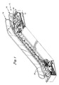
- an escalator 10 having a frame 12, a plurality of moving steps 14, and a pair of balustrade assemblies 16.
- the steps 14 are connected to a step chain 18 which is driven around a circuitous path by an electric drive motor 20.
- a handrail 22 is driven in the same direction and speed as the steps 14, as is known in the art.
- the handrails 22 enable passenger(s) (not shown) to steady themselves while riding the escalator 10.
- each balustrade assembly 16 includes a balustrade panel 24 extending up from a base 26 to support and guide a handrail (not shown).
- the base 26 includes a panel holder 28 for supporting the balustrade panel 24 (typically glass) and a plurality of enclosure panels 30.
- the panel holder 28 has an extruded or otherwise shaped cross-sectional profile consisting of a glass channel 32, a top surface 34, a bottom surface 36, and a first 38, second 40, and third 42 attachment means, all of which extend the length of the panel holder 28.
- the first attachment means 38 positioned on the side of the panel holder 28 away from the moving steps (not shown), comprises a first tab slot 44 and a first C-shaped channel 46.
- the second attachment means 40 positioned within the bottom surface 36, comprises a second C-shaped channel 48.
- the third attachment means 42 positioned on the side of the panel holder 28 adjacent the moving steps (not shown), comprises a second tab slot 50 and a third C-shaped channel 52.
- the glass channel 32 comprises a first wall 54 parallel to the balustrade panel 24 and a second wall 56 disposed at an angle to the first wall 54, thereby forming an acute angle between the two walls.
- an adjustable panel holder bracket 136 is provided for supporting the panel holder 28.
- Each adjustable bracket 136 includes a first half 138 attached to the frame 12 of the escalator and a second half 140 attached to the panel holder 28.
- Each half 138,140 includes two pairs of elliptical shaped slots 142 oriented at right angles to one another in two axes of direction.
- Fasteners 141 extend through the slots 142 of each half, thereby connecting the halves 138,140 and permitting the position of each half to be adjusted relative to the other.
- slots 142 may assume geometric shapes other than ellipses.
- the second half 140 comprises a first flange 144, a second flange 146, and a third flange 148, all of which include an open slot for receiving a fastener.
- the slot 150 in the first flange 144 includes a stop 152 at one end for locating a handrail guide 154;
- the third flange 148 is a plate welded to the body of the second half 140 to add rigidity to the glass support bracket 136.
- the enclosure panels 30 include an outer cladding 58, an outer decking 60, an inner profile 62, and a skirt panel 64.
- the inner profile 62, outer decking 60, and panel holder 28 comprise a clip means 66 which enables the inner profile 62 and outer decking 60 to be attached to the panel holder 28 in a constant aligned position, independent of the balustrade panel 24.
- the inner profile 62 and the outer-decking 60 are constantly aligned relative to the panel holder 28 and to each other.
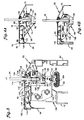
- the clip means 66 includes an outer support 68 and an inner support 70, shown in cross-section in FIG. 4A.
- the outer support 68 has a width 72 (see FIG. 2 - perspective view), an attachment clip 74, a snap clip 76, and a retaining means 78.
- the attachment clip 74 consists of a first tab 80 and a first biasing arm 82 having a boss 86.
- the retaining means 78 comprises a female receptacle in the form of a semicircular flange 88.
- the snap clip 76 comprises a second biasing arm 90 having a boss 92.
- the inner support 70 includes a hook shaped flange 94, a second tab 96, and a third biasing arm 98 having a boss 100.
- the outer decking 60 is an extrusion having a cross-sectional profile defined by an exterior surface 112, an interior surface 114, and a plurality of ribs 116 extending out from the interior surface 114.
- a first rib 117 includes a male semicircular boss 118.
- a second rib 120 includes a second boss 122.
- Each balustrade assembly 16 further includes an inner trim molding 104 and an outer trim molding 174.
- the inner trim molding 104 includes a narrow channel 106 and a broad channel 108.
- the outer trim molding 174 includes a channel 176.
- the enclosure panels 30 and the panel holder 28 may be fabricated from a number of different materials, including metal, plastics, or composites. In some embodiments, independent exterior panels 102 are attached to the enclosure panels 30 for aesthetic or wear purposes.
- the outer cladding 58 may be fabricated from materials different from the rest of the balustrade. If the cladding 58 is fabricated from material formed in sheets, such as sheet metal or sheet-plastic, a spring-type cladding support 124 (FIG. 4A) biases the cladding 58 against the outer decking 60.
- the spring-type cladding support 124 comprises a clip means 126 which attaches the cladding support 124 to the outer support 68. If the cladding 58 is thicker, or varies in thickness, an adjustable cladding support 128 (FIG.
- the adjustable cladding support 128 comprises a plate 130 having a plurality of parallel slots 132 and a biasing arm 134. Screws 129 extend through the slots 132. The screws 129 attach and permit the adjustable cladding support 128 to be adjusted as necessary depending upon the cladding 58 thickness.
- each panel holder section 28 is installed by attaching an adjustable bracket 136 to each end of the section 28.
- the second half 140 of the bracket 136 is attached to the panel holder 28 by a T-shaped fastener 172 received within the second C-shaped channel 48 in the bottom surface 36 of the panel holder 28.
- the first half 138 of the bracket 136 is welded to the frame 12.
- bracket halves 138,140 are securely bolted or otherwise fastened together. Subsequently, brackets are added along the length of each section as needed.
- the bracket halves 138,140 may be fixed to one another by a clinching method (not shown).
- the clinching method uses a cylindrical stamp which makes a concentric depression in the two pieces to be joined. The deformed metal of one piece flares within the deformed metal of the other, thereby joining the two.
- the trademark "TOX”, registered to Pressotechnik Gmbh, is used to describe this method.
- the handrail guide 154 for the handrail 22 travelling within the balustrade can be attached to the first flange 144 of the adjustable panel holder bracket 136.
- a T-shaped fastener 174 received within the slot 150 in the first flange 144, is used to attach the guide 154 to the bracket 136.
- the slot 150 is long enough to permit the handrail guide 154 to be slid laterally, thereby allowing greater access within the base 26 of the balustrade 16.
- the handrail guide 154 is located in its proper position by sliding the guide 154 back through the slot, 150 until it abuts the physical stop 152 extending out from the first flange 144 of the bracket 136.
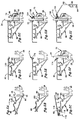
- the method of assembling the base enclosure begins by first attaching the outer support 68.
- the first tab 80 is inserted in the first tab slot 44 of the panel holder 28, and the outer support 68 is rotated clockwise until the first biasing arm 82 is biased within the first C-shaped channel 46 of the first attachment means.
- the boss 86 on the end of the first biasing arm 82 holds the outer support 68 and the panel holder 28 together.
- the outer decking 60 is attached and positioned relative to the panel holder 28 by inserting the semi-circular boss 118 on the end of the first rib 116 into the semicircular flange 88 formed in the outer support 68.
- the mating male and female relationship between the male extension 118 and the female receptacle 88 may assume a number of different geometries.
- the function of the mating male and female pieces is to prevent the outer edge 172 of the outer decking 60 from being pulled away from the outer support 68 after installation.
- the outer decking 60 can be rotated clockwise until the second biasing arm 90 is biased against the second rib 120 of the outer decking 60.
- the boss 92 attached to the end of the second biasing arm 90 holds the outer decking 60 and the outer support 68 together.
- the outer trim molding 174 is fit over the edge of the outer decking 60, inside channel 176.
- the outer trim molding 174 is adjusted to close the gap between the edge of the outer decking 60 and the balustrade panel 24.
- the outer trim 174 is removed and a tool (not shown) is inserted between the outer decking 60 and the balustrade panel 24.
- the outer decking 60 is pulled up and pivoted away from the balustrade panel 24. subsequently moving the outer decking toward the balustrade panel, causes the outer decking 60 and the outer support 68 to decouple and allows the outer decking 60 to be removed.
- the balustrade panels 24 are installed by placing a single panel 24 in the glass channel(s) 32 and loosely placing the wedge shaped clamps 158 in the channel 32. Once the panel has been aligned, the wedge clamps 158, and therefore the panels, are secured using the T-shaped fasteners 170 received within the third C-shaped channel 52. Note that the extended length 156 of the wedge clamps 158 causes their top surface 160 to always be above the top surface 34 of the panel holder 28. As a result, the moment arm of any horizontal force (not shown) applied to the balustrade panel 24 is minimized and the clamping load is distributed over a greater area. Additional balustrade panels 24 are aligned off of the first panel and secured in the same manner.
- the inner support 70 is mounted on the panel holder 28 by inserting the third biasing arm 98 into the third C-shaped channel 52 and rotating the inner support 70 clockwise until the second tab 96 may be inserted into the second tab slot 50.
- the boss 100 on the end of the third biasing arm 98 holds the inner support 70 and the panel holder 28 together.
- the inner trim molding 104 is attached by inserting the hook-shaped flange 94 into the broad channel 108 of the molding 104.
- the inner profile 62 is attached to the panel holder by inserting the upper edge 110 of the profile 62 into the narrow channel 106 of the inner trim molding 104, attached to the inner support.
- the lower edge 180 of the inner profile 62 is attached to the skirt panel 64.
- the inner support 70 could include a slot (not shown) for receiving the upper edge of the profile 62, in place of the inner trim molding 104.
- T-shaped fastener and C-shaped channel combinations used to attach the panel holder 28 to the panel holder bracket 136, the wedge clamp 158 to the panel holder 28, and the handrail guide 154 to the panel holder bracket 136 may assume a number of different mating geometries.
- the present invention provides a balustrade which can be assembled with a minimum of adjustment, which rigidly supports the handrail, which is easily maintained, and which is as inexpensive as possible.
Landscapes
- Escalators And Moving Walkways (AREA)
- Body Structure For Vehicles (AREA)
- Bridges Or Land Bridges (AREA)
Applications Claiming Priority (2)
| Application Number | Priority Date | Filing Date | Title |
|---|---|---|---|
| US08/052,880 US5542522A (en) | 1993-04-26 | 1993-04-26 | Balustrade assembly and method for assembling a balustrade assembly |
| US52880 | 1993-04-26 |
Publications (2)
| Publication Number | Publication Date |
|---|---|
| EP0622326A1 true EP0622326A1 (de) | 1994-11-02 |
| EP0622326B1 EP0622326B1 (de) | 1998-04-01 |
Family
ID=21980516
Family Applications (1)
| Application Number | Title | Priority Date | Filing Date |
|---|---|---|---|
| EP94302698A Expired - Lifetime EP0622326B1 (de) | 1993-04-26 | 1994-04-15 | Geländeraufbau und Verfahren für die Montage desselben |
Country Status (7)
| Country | Link |
|---|---|
| US (1) | US5542522A (de) |
| EP (1) | EP0622326B1 (de) |
| JP (1) | JP2548520B2 (de) |
| CN (1) | CN1047998C (de) |
| AT (1) | ATE164567T1 (de) |
| DE (1) | DE69409284T2 (de) |
| RU (1) | RU2091546C1 (de) |
Cited By (3)
| Publication number | Priority date | Publication date | Assignee | Title |
|---|---|---|---|---|
| EP0736478A3 (de) * | 1995-04-04 | 1997-03-19 | Thyssen Aufzuege Gmbh | Lagerung einer Balustradenscheibe für Fahrtreppe oder Fahrsteig |
| WO2010091519A1 (de) * | 2009-02-13 | 2010-08-19 | Beat Guhl | Vorrichtung zum befestigen von geländern mit platten aus glas oder anderen zerbrechlichen materialien |
| US9162851B2 (en) | 2013-01-18 | 2015-10-20 | Kone Corporation | Comb plate—comb plate carrier assembly and combination construction of the assembly with lifting tool |
Families Citing this family (25)
| Publication number | Priority date | Publication date | Assignee | Title |
|---|---|---|---|---|
| DE19937618B4 (de) * | 1999-08-10 | 2004-01-22 | Kone Corp. | Balustrade einer Personenförderanlage |
| US6533098B1 (en) * | 2000-03-31 | 2003-03-18 | Inventio Ag | Escalator or moving walkway with partition walls |
| US6830146B1 (en) * | 2002-08-01 | 2004-12-14 | Cargotainer Adrian Fabricators, Inc. | Guide rail system for roller-type conveyors |
| DE10360377B3 (de) * | 2003-12-22 | 2005-04-28 | Kone Corp | Sockel für eine Rolltreppe oder einen Rollsteig |
| FI20040090L (fi) * | 2004-01-22 | 2005-07-23 | Kone Corp | Liukukäytävä, -ramppi tai -porras |
| FI20040091L (fi) | 2004-01-22 | 2005-07-23 | Kone Corp | Liukukäytävä, -ramppi tai -porras |
| US20050199563A1 (en) * | 2004-03-12 | 2005-09-15 | Richter Gary M. | Merchandising system |
| FI117242B (fi) * | 2004-06-02 | 2006-08-15 | Kone Corp | Liukukäytävä, -ramppi tai -porras |
| CA2584903A1 (en) * | 2004-10-22 | 2006-04-27 | Inventio Ag | Conveyor device comprising a barrier and method for modernising a conveyor device |
| CN100478268C (zh) * | 2006-08-18 | 2009-04-15 | 西子奥的斯电梯有限公司 | 易拆卸的扶梯外盖板 |
| US20080131878A1 (en) * | 2006-12-05 | 2008-06-05 | Asuragen, Inc. | Compositions and Methods for the Detection of Small RNA |
| RU2374405C2 (ru) * | 2007-11-15 | 2009-11-27 | Роман Викторович Макаренков | Ограждение |
| JP5257868B2 (ja) * | 2008-02-15 | 2013-08-07 | 東芝エレベータ株式会社 | 乗客コンベアの目地部材 |
| JP5257870B2 (ja) * | 2008-03-06 | 2013-08-07 | 東芝エレベータ株式会社 | 乗客コンベアの欄干構造 |
| JP5442843B2 (ja) * | 2009-04-03 | 2014-03-12 | オーチス エレベータ カンパニー | 踏段フランジカバー用の調整可能なブラケット |
| CN103930631B (zh) * | 2011-09-08 | 2016-08-24 | 约翰·迈克尔·肖普夫 | 用于面板的改进夹持器 |
| JP5784219B2 (ja) | 2012-03-19 | 2015-09-24 | 三菱電機株式会社 | コンベアの欄干装置 |
| CN102838036B (zh) * | 2012-09-19 | 2014-03-26 | 苏州富士电梯有限公司 | 自动扶梯或自动人行道的进出口面板安装结构 |
| CN104085769A (zh) * | 2014-05-22 | 2014-10-08 | 杭州奥弗德机电科技有限公司 | 一种自动扶梯扶手栏板夹紧系统 |
| WO2016008721A1 (de) * | 2014-07-17 | 2016-01-21 | Inventio Ag | Verkleidungsbauteil für eine fahrtreppe oder einen fahrsteig |
| JP6351479B2 (ja) * | 2014-10-23 | 2018-07-04 | 三菱電機株式会社 | 乗客コンベヤの欄干装置 |
| CN107207215B (zh) * | 2015-01-29 | 2018-10-16 | 三菱电机株式会社 | 乘客输送机的栏杆装置 |
| CN104722996B (zh) * | 2015-03-17 | 2016-06-08 | 江南嘉捷电梯股份有限公司 | 自动扶梯上端的合拢定位装置及定位安装方法 |
| CN105084228A (zh) * | 2015-06-08 | 2015-11-25 | 徐州重型机械有限公司 | 一种围沿及覆盖件安装结构以及使用该结构的轮式起重机 |
| US10227214B1 (en) | 2018-03-13 | 2019-03-12 | Otis Elevator Company | Passenger conveyor skirt panel positioning assembly |
Citations (3)
| Publication number | Priority date | Publication date | Assignee | Title |
|---|---|---|---|---|
| US4690264A (en) * | 1986-03-31 | 1987-09-01 | Otis Elevator Company | Multifunction glassholder for escalator balustrade |
| US5029690A (en) * | 1990-09-10 | 1991-07-09 | Otis Elevator Company | Decking trim fastening for curved escalator |
| US5180047A (en) * | 1992-04-07 | 1993-01-19 | Otis Elevator Company | Balustrade and deck mounting assembly for escalator or moving walkway |
Family Cites Families (2)
| Publication number | Priority date | Publication date | Assignee | Title |
|---|---|---|---|---|
| JPS62249886A (ja) * | 1986-04-22 | 1987-10-30 | 株式会社日立製作所 | 乗客コンベア |
| US5156251A (en) * | 1992-04-07 | 1992-10-20 | Otis Elevator Company | Balustrade mounting assembly for escalator or moving walkway |
-
1993
- 1993-04-26 US US08/052,880 patent/US5542522A/en not_active Expired - Fee Related
-
1994
- 1994-04-15 EP EP94302698A patent/EP0622326B1/de not_active Expired - Lifetime
- 1994-04-15 AT AT94302698T patent/ATE164567T1/de not_active IP Right Cessation
- 1994-04-15 DE DE69409284T patent/DE69409284T2/de not_active Expired - Fee Related
- 1994-04-25 CN CN94104636A patent/CN1047998C/zh not_active Expired - Fee Related
- 1994-04-25 RU RU9494014253A patent/RU2091546C1/ru active
- 1994-04-26 JP JP6088332A patent/JP2548520B2/ja not_active Expired - Fee Related
Patent Citations (3)
| Publication number | Priority date | Publication date | Assignee | Title |
|---|---|---|---|---|
| US4690264A (en) * | 1986-03-31 | 1987-09-01 | Otis Elevator Company | Multifunction glassholder for escalator balustrade |
| US5029690A (en) * | 1990-09-10 | 1991-07-09 | Otis Elevator Company | Decking trim fastening for curved escalator |
| US5180047A (en) * | 1992-04-07 | 1993-01-19 | Otis Elevator Company | Balustrade and deck mounting assembly for escalator or moving walkway |
Cited By (3)
| Publication number | Priority date | Publication date | Assignee | Title |
|---|---|---|---|---|
| EP0736478A3 (de) * | 1995-04-04 | 1997-03-19 | Thyssen Aufzuege Gmbh | Lagerung einer Balustradenscheibe für Fahrtreppe oder Fahrsteig |
| WO2010091519A1 (de) * | 2009-02-13 | 2010-08-19 | Beat Guhl | Vorrichtung zum befestigen von geländern mit platten aus glas oder anderen zerbrechlichen materialien |
| US9162851B2 (en) | 2013-01-18 | 2015-10-20 | Kone Corporation | Comb plate—comb plate carrier assembly and combination construction of the assembly with lifting tool |
Also Published As
| Publication number | Publication date |
|---|---|
| CN1047998C (zh) | 2000-01-05 |
| RU2091546C1 (ru) | 1997-09-27 |
| RU94014253A (ru) | 1996-06-10 |
| CN1099003A (zh) | 1995-02-22 |
| DE69409284T2 (de) | 1998-11-05 |
| EP0622326B1 (de) | 1998-04-01 |
| US5542522A (en) | 1996-08-06 |
| JPH06329378A (ja) | 1994-11-29 |
| DE69409284D1 (de) | 1998-05-07 |
| ATE164567T1 (de) | 1998-04-15 |
| JP2548520B2 (ja) | 1996-10-30 |
Similar Documents
| Publication | Publication Date | Title |
|---|---|---|
| EP0622326B1 (de) | Geländeraufbau und Verfahren für die Montage desselben | |
| US4159758A (en) | Transportation apparatus | |
| US3991877A (en) | Transportation apparatus | |
| US5601179A (en) | Balustrade skirt panel | |
| EP0622325B1 (de) | Geländer für eine Rolltreppe oder dergleichen | |
| EP0404746B1 (de) | Befestigungsbügel für ein tragbares Fernsprechgerät | |
| GB2190059A (en) | A passenger conveyor | |
| EP0648704B1 (de) | Balustrade-Eingangsgehäuse für Handlauf | |
| US7165656B2 (en) | Elevator and guide fixing bracket for an elevator | |
| US20070170013A1 (en) | Elevator rail support bracket | |
| WO1998018709A1 (en) | Elevator guide rail | |
| KR19990028231A (ko) | 핸드레일용 엄지기둥 안내체 | |
| EP2749518B1 (de) | Aufzugsführungsschienenanordnung und Stütze | |
| US5186302A (en) | Escalator skirt and deck panel installation | |
| EP0608125B1 (de) | Einfassungsblende für Rolltreppenbalustrade | |
| US5458220A (en) | Balustrade for a passenger conveyor | |
| US5181595A (en) | Roller supporting assembly for escalator or moving walkway handrail newels | |
| EP0659676A1 (de) | Kammplatte für Rolltreppen oder Fahrsteige | |
| EP1828030B1 (de) | Handlaufführung für personenbeförderer | |
| CN116685550B (zh) | 用于自动扶梯或自动人行道的导轨分段的轨道固定装置 | |
| WO2005118455A2 (en) | Travelator, moving ramp or escalator | |
| AU2024336838A1 (en) | Enclosure of an escalator or a moving walkway | |
| JP2002348084A (ja) | 乗客コンベアの欄干 | |
| HK1037591A (en) | Glass balustrade for a passenger transportation device | |
| HK1037591B (en) | Glass balustrade for a passenger transportation device |
Legal Events
| Date | Code | Title | Description |
|---|---|---|---|
| PUAI | Public reference made under article 153(3) epc to a published international application that has entered the european phase |
Free format text: ORIGINAL CODE: 0009012 |
|
| AK | Designated contracting states |
Kind code of ref document: A1 Designated state(s): AT DE FR GB |
|
| 17P | Request for examination filed |
Effective date: 19940928 |
|
| 17Q | First examination report despatched |
Effective date: 19960305 |
|
| GRAG | Despatch of communication of intention to grant |
Free format text: ORIGINAL CODE: EPIDOS AGRA |
|
| GRAG | Despatch of communication of intention to grant |
Free format text: ORIGINAL CODE: EPIDOS AGRA |
|
| GRAH | Despatch of communication of intention to grant a patent |
Free format text: ORIGINAL CODE: EPIDOS IGRA |
|
| GRAH | Despatch of communication of intention to grant a patent |
Free format text: ORIGINAL CODE: EPIDOS IGRA |
|
| GRAA | (expected) grant |
Free format text: ORIGINAL CODE: 0009210 |
|
| AK | Designated contracting states |
Kind code of ref document: B1 Designated state(s): AT DE FR GB |
|
| REF | Corresponds to: |
Ref document number: 164567 Country of ref document: AT Date of ref document: 19980415 Kind code of ref document: T |
|
| ET | Fr: translation filed | ||
| REF | Corresponds to: |
Ref document number: 69409284 Country of ref document: DE Date of ref document: 19980507 |
|
| PLBE | No opposition filed within time limit |
Free format text: ORIGINAL CODE: 0009261 |
|
| STAA | Information on the status of an ep patent application or granted ep patent |
Free format text: STATUS: NO OPPOSITION FILED WITHIN TIME LIMIT |
|
| 26N | No opposition filed | ||
| PGFP | Annual fee paid to national office [announced via postgrant information from national office to epo] |
Ref country code: FR Payment date: 20000313 Year of fee payment: 7 Ref country code: AT Payment date: 20000313 Year of fee payment: 7 |
|
| PGFP | Annual fee paid to national office [announced via postgrant information from national office to epo] |
Ref country code: GB Payment date: 20000321 Year of fee payment: 7 |
|
| PG25 | Lapsed in a contracting state [announced via postgrant information from national office to epo] |
Ref country code: GB Free format text: LAPSE BECAUSE OF NON-PAYMENT OF DUE FEES Effective date: 20010415 Ref country code: AT Free format text: LAPSE BECAUSE OF NON-PAYMENT OF DUE FEES Effective date: 20010415 |
|
| PG25 | Lapsed in a contracting state [announced via postgrant information from national office to epo] |
Ref country code: FR Free format text: THE PATENT HAS BEEN ANNULLED BY A DECISION OF A NATIONAL AUTHORITY Effective date: 20010430 |
|
| GBPC | Gb: european patent ceased through non-payment of renewal fee |
Effective date: 20010415 |
|
| REG | Reference to a national code |
Ref country code: FR Ref legal event code: ST |
|
| PGFP | Annual fee paid to national office [announced via postgrant information from national office to epo] |
Ref country code: DE Payment date: 20060428 Year of fee payment: 13 |
|
| PG25 | Lapsed in a contracting state [announced via postgrant information from national office to epo] |
Ref country code: DE Free format text: LAPSE BECAUSE OF NON-PAYMENT OF DUE FEES Effective date: 20071101 |