EP0622536A2 - Circuit de commande pour injecteur de carburant électronique - Google Patents
Circuit de commande pour injecteur de carburant électronique Download PDFInfo
- Publication number
- EP0622536A2 EP0622536A2 EP94106745A EP94106745A EP0622536A2 EP 0622536 A2 EP0622536 A2 EP 0622536A2 EP 94106745 A EP94106745 A EP 94106745A EP 94106745 A EP94106745 A EP 94106745A EP 0622536 A2 EP0622536 A2 EP 0622536A2
- Authority
- EP
- European Patent Office
- Prior art keywords
- resistor
- solenoid coil
- transistor
- fuel injector
- controlling
- Prior art date
- Legal status (The legal status is an assumption and is not a legal conclusion. Google has not performed a legal analysis and makes no representation as to the accuracy of the status listed.)
- Withdrawn
Links
Images
Classifications
-
- H—ELECTRICITY
- H01—ELECTRIC ELEMENTS
- H01F—MAGNETS; INDUCTANCES; TRANSFORMERS; SELECTION OF MATERIALS FOR THEIR MAGNETIC PROPERTIES
- H01F7/00—Magnets
- H01F7/06—Electromagnets; Actuators including electromagnets
- H01F7/08—Electromagnets; Actuators including electromagnets with armatures
- H01F7/18—Circuit arrangements for obtaining desired operating characteristics, e.g. for slow operation, for sequential energisation of windings, for high-speed energisation of windings
- H01F7/1805—Circuit arrangements for holding the operation of electromagnets or for holding the armature in attracted position with reduced energising current
- H01F7/1816—Circuit arrangements for holding the operation of electromagnets or for holding the armature in attracted position with reduced energising current making use of an energy accumulator
-
- F—MECHANICAL ENGINEERING; LIGHTING; HEATING; WEAPONS; BLASTING
- F02—COMBUSTION ENGINES; HOT-GAS OR COMBUSTION-PRODUCT ENGINE PLANTS
- F02D—CONTROLLING COMBUSTION ENGINES
- F02D41/00—Electrical control of supply of combustible mixture or its constituents
- F02D41/20—Output circuits, e.g. for controlling currents in command coils
-
- F—MECHANICAL ENGINEERING; LIGHTING; HEATING; WEAPONS; BLASTING
- F02—COMBUSTION ENGINES; HOT-GAS OR COMBUSTION-PRODUCT ENGINE PLANTS
- F02D—CONTROLLING COMBUSTION ENGINES
- F02D41/00—Electrical control of supply of combustible mixture or its constituents
- F02D41/20—Output circuits, e.g. for controlling currents in command coils
- F02D2041/2017—Output circuits, e.g. for controlling currents in command coils using means for creating a boost current or using reference switching
-
- F—MECHANICAL ENGINEERING; LIGHTING; HEATING; WEAPONS; BLASTING
- F02—COMBUSTION ENGINES; HOT-GAS OR COMBUSTION-PRODUCT ENGINE PLANTS
- F02D—CONTROLLING COMBUSTION ENGINES
- F02D41/00—Electrical control of supply of combustible mixture or its constituents
- F02D41/20—Output circuits, e.g. for controlling currents in command coils
- F02D2041/202—Output circuits, e.g. for controlling currents in command coils characterised by the control of the circuit
- F02D2041/2024—Output circuits, e.g. for controlling currents in command coils characterised by the control of the circuit the control switching a load after time-on and time-off pulses
- F02D2041/2027—Control of the current by pulse width modulation or duty cycle control
-
- F—MECHANICAL ENGINEERING; LIGHTING; HEATING; WEAPONS; BLASTING
- F02—COMBUSTION ENGINES; HOT-GAS OR COMBUSTION-PRODUCT ENGINE PLANTS
- F02D—CONTROLLING COMBUSTION ENGINES
- F02D41/00—Electrical control of supply of combustible mixture or its constituents
- F02D41/20—Output circuits, e.g. for controlling currents in command coils
- F02D2041/202—Output circuits, e.g. for controlling currents in command coils characterised by the control of the circuit
- F02D2041/2031—Control of the current by means of delays or monostable multivibrators
-
- F—MECHANICAL ENGINEERING; LIGHTING; HEATING; WEAPONS; BLASTING
- F02—COMBUSTION ENGINES; HOT-GAS OR COMBUSTION-PRODUCT ENGINE PLANTS
- F02D—CONTROLLING COMBUSTION ENGINES
- F02D41/00—Electrical control of supply of combustible mixture or its constituents
- F02D41/20—Output circuits, e.g. for controlling currents in command coils
- F02D2041/202—Output circuits, e.g. for controlling currents in command coils characterised by the control of the circuit
- F02D2041/2058—Output circuits, e.g. for controlling currents in command coils characterised by the control of the circuit using information of the actual current value
-
- H—ELECTRICITY
- H01—ELECTRIC ELEMENTS
- H01H—ELECTRIC SWITCHES; RELAYS; SELECTORS; EMERGENCY PROTECTIVE DEVICES
- H01H47/00—Circuit arrangements not adapted to a particular application of the relay and designed to obtain desired operating characteristics or to provide energising current
- H01H47/22—Circuit arrangements not adapted to a particular application of the relay and designed to obtain desired operating characteristics or to provide energising current for supplying energising current for relay coil
- H01H47/32—Energising current supplied by semiconductor device
- H01H47/325—Energising current supplied by semiconductor device by switching regulator
Definitions
- the present invention relates generally to electronic fuel injector systems for internal combustion engines, and more particularly, to an electronic fuel injector driver circuit for controlling electromagnetic fuel injector valves for use on internal combustion engines.
- fuel injector system technology must continue to advance forward. Systems which provide improved performance, better fuel economy as well as reduced exhaust emissions must overcome inherent design limitations which constrain fuel injector valve response time.
- Primary factors affecting fuel injector valve performance are injector solenoid coil current rise and fall times.
- fuel injector response time has been improved by rapidly building the injector solenoid coil current until the injector valve begins to open.
- the fuel injector valve driver circuit then reduces the applied current to a lower 'holding' value to avoid overheating the injector solenoid coil winding. Finally, current is abruptly turned 'off', and injector solenoid coil current is recirculated through the coil giving a fairly slow injector valve 'close' time.
- Fuel injector systems for two-stroke internal combustion engines must utilize an improved version of this control method.
- the fuel injector system must have the capability of being able to actuate and hold open fuel injector valves for between 200 and 2,000 microseconds which is much shorter than the 2,000 to 10,000 microseconds found in four-stroke internal combustion engines. Short actuation times require ultra-fast fuel injector valve response.
- an electronic fuel injector driver circuit which overcomes the inherent electromechanical fuel injector valve delay problem which can clearly be illustrated in the example below.
- a two-stroke internal combustion engine has an operating condition which requires a five hundred (500) microsecond fuel injector valve actuation time (includes open, hold and close time). This requires that the fuel injection driver circuit produce an electrical pulse five hundred (500) microseconds long.
- This 500 microsecond valve actuation pulse width involves building up the injector solenoid coil to the 'opening' current of approximately 6-9 amps in approximately 150 microseconds or less, sustain the 'opening' current value for approximately 50 microseconds, ramp down to the 'hold' value of 1-2 amps in less than 50 microseconds, sustain at the 'hold' value for 250 microseconds, finally ramping down to zero, closing the injector valve.
- Fuel injectors developed for two-stroke internal combustion engine applications typically have an inductance of between 2-3 millihenries and a resistance of 1-2 ohms. Choosing a typical value of 2.4 mH and 1.8 ohms, injector valve time lag can be shown using Equation 1:
- the present invention is an electronic fuel injector driver circuit for controlling electromagnetic fuel injector valves for an internal combustion engine including a solenoid coil for at least one electromagnetic fuel injector valve.
- the circuit also includes a one shot timer means for sending a predetermined timing signal and a means interconnecting the one shot timer means and the solenoid coil for controlling the high side of the solenoid coil in response to the predetermined timing signal.
- the circuit includes a means connected to the solenoid coil for controlling the low side of the solenoid coil in response to the predetermined timing signal and a switchable voltage reference means connected to the means for controlling the low side of the solenoid coil for controlling current through the solenoid coil.
- the electronic fuel injector driver circuit decreases injector valve closing time by decreasing injector solenoid coil current fall time. This is accomplished by allowing the fly-back voltage, created at injector valve deactivation, to reach levels 15-20 times the battery potential.
- Another advantage of the present invention is that the electronic fuel injection driver circuit increases injector valve opening response by decreasing injector solenoid coil current rise time. This is accomplished by applying a potential of eight (8) to ten (10) times the battery potential to the injector solenoid coil. Referring back to Equation 1, it can be shown that boosting the input battery voltage, V BAT , by a factor of eight will decrease the injector solenoid coil current rise time from approximately 310 milliseconds to about 159 milliseconds.
- the boost voltage, V BST is achieved by DC to DC converter techniques.
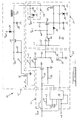
- FIG. 1 is a schematic diagram of an electronic fuel injector driver circuit according to the present invention.
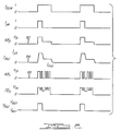
- FIG. 2 is a timing diagram depicting the operation of the electronic fuel injector driver circuit of FIG. 1.
- an electronic fuel injector driver circuit 10 is illustrated for use on a two-stroke internal combustion engine (not shown).
- the driver circuit 10, according to the present invention is suitable for use with multi-point direct fuel injector systems.
- a discussion of fuel injector control and driver circuits is presented in U.S. Patent No. 4,631,628 to Kissel and is hereby expressly incorporated by reference.
- the driver circuit 10 includes a one shot timer circuit, generally indicated at 11, which sends a timing signal.
- the one shot timer circuit 11 includes a capacitor 12 which is connected to a resistor 14 and an operational amplifier 16.
- the resistor 14 is connected to a voltage supply such as five (5) volts.
- the operational amplifier 16 is also connected to the voltage supply.
- the driver circuit 10 also includes a first controller circuit, generally indicated at 17, which controls a high side of a solenoid coil 30 to be described.
- the first controller circuit 17 includes a transistor 18 whose gate is connected to the operational amplifier 16.
- the first controller circuit 17 also includes a resistor 20 connected to the drain of the transistor 18 and a resistor 22 connected to the resistor 20 and a voltage source, V BAT .
- the first controller circuit 17 includes a transistor 24 having its base and emitter connected across the resistor 22. The collector of the transistor 24 is connected to a diode 26 which also is connected to a voltage source, V BAT , such as a vehicle battery (not shown).
- the first controller circuit 17 further includes a capacitor 28 which is then connected between the diode 26 and a high side of the solenoid coil 30 and ground.
- the first controller circuit 17 regulates the amount of current allowed to flow through the solenoid coil 30.
- the solenoid coil 30 is for an electromagnetic fuel injector (not shown) of the fuel injector system (not shown).
- the driver circuit 10 also includes a second controller circuit, generally indicated at 31, which controls a low side of the solenoid coil 30.
- the second controller circuit 31 includes a transistor 32 having its drain connected to the low side of the solenoid coil 30.
- the second controller circuit 31 also includes a resistor 34 connected between the source of the transistor 32 and ground.
- the second controller circuit 31 further includes a diode 36 and a capacitor 38 both connected to the gate of the transistor 32 and ground.
- the second controller circuit 31 includes a transistor 40 whose emitter is connected to the gate of the transistor 32.
- the second controller circuit 31 also includes a resistor 42 connected between the voltage source V BAT and the collector of the transistor 40 and a resistor 44 connected between the voltage source V BAT and the base of the transistor 40.
- the second controller circuit 31 further includes a diode 46 connected between the emitter and base of the transistor 40 and an operational amplifier 48 whose output is connected to the base of the transistor 40.
- the second controller circuit 31 includes a resistor 50 connected to the source of the transistor 32 and a negative input of the operational amplifier 48 and a resistor 52 connected between a voltage source such as five (5) volts and the negative input of the operational amplifier 48.
- the second controller circuit 31 regulates the amount of current allowed to build through the solenoid coil 30.
- the driver circuit 10 also includes a switchable voltage reference circuit, generally indicated at 53, which further includes a dual level switchable voltage reference with an absolute off state.
- the switchable voltage reference circuit 53 includes a resistor 54 connected to the positive input of the operational amplifier 48 and the source of a transistor 56.
- the switchable voltage reference circuit 53 also includes a resistor 58 connected between the positive input of the operational amplifier 48 and the drain of the transistor 56.
- the gate of the transistor 56 is also connected to the operational amplifier 16.
- the switchable voltage reference circuit 53 includes a resistor 60 connected between the positive input of the operational amplifier 48 and the collector of a transistor 62.
- the switchable voltage reference circuit 53 includes a resistor 64 connected to the emitter of the transistor 62 and the collector of a transistor 66.
- the switchable voltage reference circuit 53 includes a resistor 68 connected to the base of the transistor 62 and the collector of the transistor 66.
- the switchable voltage reference circuit 53 includes a resistor 70 connected between the collector of the transistor 66 and the operational amplifier 16.
- the switchable voltage reference circuit 53 includes a resistor 72 connected between the base of the transistor 66 and the operational amplifier 16.
- the switchable voltage reference circuit 53 controls the voltage follower current sink.
- the driver circuit 10 also includes a flyback voltage control circuit, generally indicated at 73, which limits the amount of potential to the solenoid coil 30 during coil de-activation.
- the clamp circuit 73 includes a capacitor 74 connected between the low side of the solenoid coil 30 and ground.
- the clamp circuit 73 further includes a diode 76 connected between the low side of the solenoid coil 30 and ground.
- Time period, t pk is a sub-interval of T DUR and is created by the programmable one shot timer circuit 11.
- a software programmable timer (not shown) can replace the programmable one-shot timer circuit 11.
- the transistor 24 is turned off, allowing the diode 26 to begin conducting, which supplies the necessary amount of 'hold' current to the solenoid coil 30 and keeps the injector valve in the open position. It should be appreciated that the resistors 20, 22, and the transistor 18 provide a means of switching the base of the transistor 24.
- the resistors 72, 70, 64, 68, 60, 54, 58 and the transistors 66, 56, and 62 provide a dual level switchable voltage reference with an absolute 'off' state.
- the dual reference voltage levels are shown in FIG. 2, waveforms 80 and 82, referring to pins 1 and 3 of comparator 48, as V I1 and V I2 .
- This dual reference voltage signal controls the 'voltage follower' current sink circuit consisting of the comparator 48, transistors 32 and 40, resistors 34, 42, 44 and diodes 36 and 46.
- the current sink circuit controls the 'low side' of the solenoid coil 30.
- the current sink circuit allows the current to build through the fuel injector by closing the transistor 32.
- the input signal T DUR controls the duration of injector valve actuation, while t pk , a sub-interval of T DUR , controls how long the peak current, I pk , and the boost voltage, V BST , is applied to the solenoid coil 30.
- the comparator 48 begins to switch 'on' and 'off', allowing the transistor 32's gate voltage, held high by the capacitor 38, to oscillate about its turn-on threshold level. This action regulates the injector current at the peak level and continues until time interval, t p , has elapsed.
- the comparator 48 begins switching to regulate the current at the injector valve to the 'hold' current level, I hld , until control input T DUR goes low. At that time, the comparator 48 turns the transistor 32 'off'. Once again, a very short injector current fall time is achieved by allowing the fly-back voltage created at the low side of the solenoid coil 30 to go to a high value with respect to V BAT .
- This circuit 10 also features low power dissipation operation, achieved by disconnecting boosted voltage with the transistor 24. With the boost voltage disconnected during injector firings, all the hold current is supplied by V BAT . This allows for a considerable reduction in power dissipated by the solenoid coil 30. Power dissipation in the transistor 32 can be reduced by removing the capacitor 38, thereby allowing the current to 'switch' rather than regulate at the desired levels. This action reduces the 'on' time or duty cycle of the transistor thereby reducing its power dissipation.
Landscapes
- Engineering & Computer Science (AREA)
- Physics & Mathematics (AREA)
- Electromagnetism (AREA)
- Power Engineering (AREA)
- Chemical & Material Sciences (AREA)
- Combustion & Propulsion (AREA)
- Mechanical Engineering (AREA)
- General Engineering & Computer Science (AREA)
- Fuel-Injection Apparatus (AREA)
- Electrical Control Of Air Or Fuel Supplied To Internal-Combustion Engine (AREA)
Applications Claiming Priority (2)
| Application Number | Priority Date | Filing Date | Title |
|---|---|---|---|
| US08/056,145 US5430601A (en) | 1993-04-30 | 1993-04-30 | Electronic fuel injector driver circuit |
| US56145 | 1993-04-30 |
Publications (2)
| Publication Number | Publication Date |
|---|---|
| EP0622536A2 true EP0622536A2 (fr) | 1994-11-02 |
| EP0622536A3 EP0622536A3 (fr) | 1995-11-22 |
Family
ID=22002463
Family Applications (1)
| Application Number | Title | Priority Date | Filing Date |
|---|---|---|---|
| EP94106745A Withdrawn EP0622536A3 (fr) | 1993-04-30 | 1994-04-28 | Circuit de commande pour injecteur de carburant électronique. |
Country Status (4)
| Country | Link |
|---|---|
| US (1) | US5430601A (fr) |
| EP (1) | EP0622536A3 (fr) |
| AU (1) | AU6077094A (fr) |
| CA (1) | CA2122217A1 (fr) |
Cited By (4)
| Publication number | Priority date | Publication date | Assignee | Title |
|---|---|---|---|---|
| EP0821149A1 (fr) * | 1996-07-23 | 1998-01-28 | C.R.F. Società Consortile per Azioni | Appareil de commande de charges inductives, en particulier pour injecteurs de systèmes à injection de moteur à combustion interne |
| WO2000023706A1 (fr) * | 1998-10-22 | 2000-04-27 | Siemens Automotive Corporation | Circuit de commande a soupape electromecanique et procede associe |
| EP1132603A3 (fr) * | 2000-03-09 | 2002-06-05 | Robert Bosch Gmbh | Circuit de commande d'au moins une charge électromagnétique |
| WO2011000640A1 (fr) * | 2009-07-03 | 2011-01-06 | Continental Automotive Gmbh | Procédé et dispositif permettant de faire fonctionner un moteur à combustion interne |
Families Citing this family (23)
| Publication number | Priority date | Publication date | Assignee | Title |
|---|---|---|---|---|
| JP3836565B2 (ja) * | 1997-04-18 | 2006-10-25 | 三菱電機株式会社 | 筒内噴射式インジェクタの制御装置 |
| US5898562A (en) * | 1997-05-09 | 1999-04-27 | Avx Corporation | Integrated dual frequency noise attenuator |
| DE19732854B4 (de) * | 1997-07-30 | 2006-04-20 | Mitsubishi Denki K.K. | Steuervorrichtung zum Steuern einer Kraftstoffeinspritzvorrichtung einer Brennkraftmaschine |
| US6208498B1 (en) * | 1997-12-17 | 2001-03-27 | Jatco Transtechnology Ltd. | Driving method and driving apparatus of a solenoid and solenoid driving control apparatus |
| DE19815628C1 (de) * | 1998-04-07 | 1999-09-23 | Siemens Ag | Steuereinrichtung für ein Kraftstoff-Einspritzsystem |
| DE19833830A1 (de) * | 1998-07-28 | 2000-02-03 | Bosch Gmbh Robert | Verfahren und Vorrichtung zur Steuerung wenigstens eines Magnetventils |
| US6493204B1 (en) | 1999-07-09 | 2002-12-10 | Kelsey-Hayes Company | Modulated voltage for a solenoid valve |
| US6283095B1 (en) | 1999-12-16 | 2001-09-04 | Bombardier Motor Corporation Of America | Quick start fuel injection apparatus and method |
| ITBO20000489A1 (it) * | 2000-08-04 | 2002-02-04 | Magneti Marelli Spa | Metodo e dispositivo per il pilotaggio di un iniettore in un motore acombustione interna . |
| ITBO20020359A1 (it) * | 2002-06-07 | 2003-12-09 | Magneti Marelli Powertrain Spa | Metodo di pilotaggio di un iniettore di carburante con legge di comando differenziata in funzione del tempo di iniezione |
| US7057870B2 (en) * | 2003-07-17 | 2006-06-06 | Cummins, Inc. | Inductive load driver circuit and system |
| US7596445B2 (en) * | 2007-02-26 | 2009-09-29 | Ford Global Technologies, Llc | Method for improving the operation of electrically controlled actuators for an internal combustion engine |
| US8214132B2 (en) * | 2010-09-17 | 2012-07-03 | Caterpillar Inc. | Efficient wave form to control fuel system |
| CN102278220A (zh) * | 2011-07-01 | 2011-12-14 | 天津大学 | 新型柴油机电控喷油器续流电路 |
| US9188074B2 (en) * | 2012-12-03 | 2015-11-17 | Delphi Technologies, Inc. | Fuel injector control system and component for piecewise injector signal generation |
| JP5849975B2 (ja) * | 2013-02-25 | 2016-02-03 | 株式会社デンソー | 燃料噴射制御装置および燃料噴射システム |
| US9567934B2 (en) | 2013-06-19 | 2017-02-14 | Enviro Fuel Technology, Lp | Controllers and methods for a fuel injected internal combustion engine |
| CN104500298B (zh) * | 2014-12-03 | 2017-01-25 | 中国第一汽车股份有限公司无锡油泵油嘴研究所 | 柴油机压电陶瓷喷油器的驱动电流控制电路 |
| JP6104340B1 (ja) * | 2015-09-30 | 2017-03-29 | 三菱電機株式会社 | 車載エンジン制御装置 |
| GB2567651B (en) * | 2017-10-18 | 2020-08-12 | Delphi Automotive Systems Lux | Arrangement to transmit data from an ECU to a fuel injector |
| US10371082B1 (en) | 2018-01-22 | 2019-08-06 | Delphi Technologies Ip Limited | Fuel injector control including state selection based on a control signal characteristic |
| US10221800B1 (en) | 2018-01-22 | 2019-03-05 | Delphi Technologies Ip Limited | Fuel injector control including adaptive response |
| CN112746920B (zh) * | 2019-10-29 | 2024-01-23 | 卓品智能科技无锡有限公司 | 一种压电晶体喷油器驱动电路 |
Family Cites Families (12)
| Publication number | Priority date | Publication date | Assignee | Title |
|---|---|---|---|---|
| FR2345595A1 (fr) * | 1976-03-26 | 1977-10-21 | Bosch Gmbh Robert | Installation pour la commande, avec un courant regle, d'organes de manoeuvre electromagnetiques |
| US4205648A (en) * | 1977-05-19 | 1980-06-03 | Chrysler Corporation | Fuel circuit for an internal combustion engine |
| DE2828678A1 (de) * | 1978-06-30 | 1980-04-17 | Bosch Gmbh Robert | Verfahren und einrichtung zum betrieb eines elektromagnetischen verbrauchers, insbesondere eines einspritzventils in brennkraftmaschinen |
| JPS5675956A (en) * | 1979-11-27 | 1981-06-23 | Nippon Denso Co Ltd | Injector driving circuit |
| US4327693A (en) * | 1980-02-01 | 1982-05-04 | The Bendix Corporation | Solenoid driver using single boost circuit |
| JPS5851233A (ja) * | 1981-09-21 | 1983-03-25 | Hitachi Ltd | 燃料噴射弁駆動回路 |
| US4631628A (en) * | 1983-06-08 | 1986-12-23 | Chrysler Motors Corporation | Electronic fuel injector driver circuit |
| US4674460A (en) * | 1985-09-30 | 1987-06-23 | Chrysler Motors Corporation | Fuel injection system |
| DE3616356A1 (de) * | 1986-05-15 | 1987-11-19 | Vdo Schindling | Verfahren und schaltungsanordnung zur ansteuerung eines einspritzventils |
| US4764840A (en) * | 1986-09-26 | 1988-08-16 | Motorola, Inc. | Dual limit solenoid driver control circuit |
| US5159522A (en) * | 1990-02-27 | 1992-10-27 | Dana Corporation | Electric clutch actuator |
| FR2667357A1 (fr) * | 1990-09-28 | 1992-04-03 | Renault | Dispositif de commande d'injecteurs de combustible dans un moteur a combustion interne. |
-
1993
- 1993-04-30 US US08/056,145 patent/US5430601A/en not_active Expired - Lifetime
-
1994
- 1994-04-26 CA CA002122217A patent/CA2122217A1/fr not_active Abandoned
- 1994-04-28 AU AU60770/94A patent/AU6077094A/en not_active Abandoned
- 1994-04-28 EP EP94106745A patent/EP0622536A3/fr not_active Withdrawn
Cited By (7)
| Publication number | Priority date | Publication date | Assignee | Title |
|---|---|---|---|---|
| EP0821149A1 (fr) * | 1996-07-23 | 1998-01-28 | C.R.F. Società Consortile per Azioni | Appareil de commande de charges inductives, en particulier pour injecteurs de systèmes à injection de moteur à combustion interne |
| US5877931A (en) * | 1996-07-23 | 1999-03-02 | C.R.F. Societa' Consortile Per Azioni | Device for controlling inductive loads, in particular of injectors of an internal combustion engine injection system |
| WO2000023706A1 (fr) * | 1998-10-22 | 2000-04-27 | Siemens Automotive Corporation | Circuit de commande a soupape electromecanique et procede associe |
| US6367719B1 (en) | 1998-10-22 | 2002-04-09 | Siemens Automotive Corporation | Electromechanical valve driver circuit and method |
| EP1132603A3 (fr) * | 2000-03-09 | 2002-06-05 | Robert Bosch Gmbh | Circuit de commande d'au moins une charge électromagnétique |
| WO2011000640A1 (fr) * | 2009-07-03 | 2011-01-06 | Continental Automotive Gmbh | Procédé et dispositif permettant de faire fonctionner un moteur à combustion interne |
| US8807120B2 (en) | 2009-07-03 | 2014-08-19 | Continental Automotive Gmbh | Method and device of operating an internal combustion engine |
Also Published As
| Publication number | Publication date |
|---|---|
| EP0622536A3 (fr) | 1995-11-22 |
| US5430601A (en) | 1995-07-04 |
| CA2122217A1 (fr) | 1994-10-31 |
| AU6077094A (en) | 1994-11-03 |
Similar Documents
| Publication | Publication Date | Title |
|---|---|---|
| US5430601A (en) | Electronic fuel injector driver circuit | |
| US10598114B2 (en) | Fuel injection controller and fuel injection system | |
| US8081498B2 (en) | Internal combustion engine controller | |
| US5979412A (en) | Inductive discharge injector driver | |
| US6123092A (en) | Electromagnetic solenoid valve drive circuit | |
| EP0297584B1 (fr) | Système d'allumage pour moteur à combustion interne | |
| US4355619A (en) | Fast response two coil solenoid driver | |
| US5975057A (en) | Fuel injector control circuit and system with boost and battery switching, and method therefor | |
| US7832378B2 (en) | Device for switching inductive fuel injection valves | |
| CN106917692B (zh) | 利用开启持续时间的喷射器控制方法 | |
| US5940262A (en) | Control circuit for an electromagnetic device for controlling an electromagnetic fuel control valve | |
| JP2002364768A (ja) | 電磁弁駆動装置 | |
| US4753207A (en) | Low voltage supply control system for fuel injectors | |
| AU6414596A (en) | Method for controlling the ignition time in internal combustion engines | |
| JPH11329831A (ja) | インダクタンスのスイッチング方法及び装置 | |
| JP3268244B2 (ja) | 電磁弁駆動回路 | |
| JP3268245B2 (ja) | 電磁弁駆動回路 | |
| US6122158A (en) | Wide voltage range driver circuit for a fuel injector | |
| JP3036105B2 (ja) | ピエゾアクチュエータの駆動回路 | |
| JP3094020B2 (ja) | 電磁付勢部材を励起する切換装置および同装置の動作方法 | |
| JPH0861125A (ja) | アクチュエータ駆動回路 | |
| JP3460258B2 (ja) | 電磁弁駆動回路 | |
| JP2001032740A (ja) | インジェクタ駆動方法 | |
| JP2001055948A (ja) | エンジン制御装置 | |
| JPH1077925A (ja) | 燃料噴射装置及び方法 |
Legal Events
| Date | Code | Title | Description |
|---|---|---|---|
| PUAI | Public reference made under article 153(3) epc to a published international application that has entered the european phase |
Free format text: ORIGINAL CODE: 0009012 |
|
| AK | Designated contracting states |
Kind code of ref document: A2 Designated state(s): AT DE FR GB SE |
|
| PUAL | Search report despatched |
Free format text: ORIGINAL CODE: 0009013 |
|
| AK | Designated contracting states |
Kind code of ref document: A3 Designated state(s): AT DE FR GB SE |
|
| STAA | Information on the status of an ep patent application or granted ep patent |
Free format text: STATUS: THE APPLICATION IS DEEMED TO BE WITHDRAWN |
|
| 18D | Application deemed to be withdrawn |
Effective date: 19960523 |