EP0622600B1 - Refroidisseur d'huile du type à plaques empilées - Google Patents
Refroidisseur d'huile du type à plaques empilées Download PDFInfo
- Publication number
- EP0622600B1 EP0622600B1 EP94103500A EP94103500A EP0622600B1 EP 0622600 B1 EP0622600 B1 EP 0622600B1 EP 94103500 A EP94103500 A EP 94103500A EP 94103500 A EP94103500 A EP 94103500A EP 0622600 B1 EP0622600 B1 EP 0622600B1
- Authority
- EP
- European Patent Office
- Prior art keywords
- disks
- housing
- oil cooler
- oil
- cooler according
- Prior art date
- Legal status (The legal status is an assumption and is not a legal conclusion. Google has not performed a legal analysis and makes no representation as to the accuracy of the status listed.)
- Expired - Lifetime
Links
- 238000007789 sealing Methods 0.000 claims description 10
- 239000000498 cooling water Substances 0.000 claims description 9
- 229910000838 Al alloy Inorganic materials 0.000 claims description 2
- 238000010276 construction Methods 0.000 claims description 2
- 238000004512 die casting Methods 0.000 claims description 2
- 229910052751 metal Inorganic materials 0.000 claims description 2
- 239000002184 metal Substances 0.000 claims description 2
- 238000001816 cooling Methods 0.000 description 2
- 230000000694 effects Effects 0.000 description 2
- 238000004519 manufacturing process Methods 0.000 description 2
- 239000007788 liquid Substances 0.000 description 1
- 239000000463 material Substances 0.000 description 1
- 239000006187 pill Substances 0.000 description 1
- 238000005476 soldering Methods 0.000 description 1
Images

Classifications
-
- F—MECHANICAL ENGINEERING; LIGHTING; HEATING; WEAPONS; BLASTING
- F28—HEAT EXCHANGE IN GENERAL
- F28D—HEAT-EXCHANGE APPARATUS, NOT PROVIDED FOR IN ANOTHER SUBCLASS, IN WHICH THE HEAT-EXCHANGE MEDIA DO NOT COME INTO DIRECT CONTACT
- F28D9/00—Heat-exchange apparatus having stationary plate-like or laminated conduit assemblies for both heat-exchange media, the media being in contact with different sides of a conduit wall
- F28D9/0031—Heat-exchange apparatus having stationary plate-like or laminated conduit assemblies for both heat-exchange media, the media being in contact with different sides of a conduit wall the conduits for one heat-exchange medium being formed by paired plates touching each other
- F28D9/0043—Heat-exchange apparatus having stationary plate-like or laminated conduit assemblies for both heat-exchange media, the media being in contact with different sides of a conduit wall the conduits for one heat-exchange medium being formed by paired plates touching each other the plates having openings therein for circulation of at least one heat-exchange medium from one conduit to another
-
- F—MECHANICAL ENGINEERING; LIGHTING; HEATING; WEAPONS; BLASTING
- F28—HEAT EXCHANGE IN GENERAL
- F28F—DETAILS OF HEAT-EXCHANGE AND HEAT-TRANSFER APPARATUS, OF GENERAL APPLICATION
- F28F9/00—Casings; Header boxes; Auxiliary supports for elements; Auxiliary members within casings
- F28F9/005—Other auxiliary members within casings, e.g. internal filling means or sealing means
-
- F—MECHANICAL ENGINEERING; LIGHTING; HEATING; WEAPONS; BLASTING
- F01—MACHINES OR ENGINES IN GENERAL; ENGINE PLANTS IN GENERAL; STEAM ENGINES
- F01M—LUBRICATING OF MACHINES OR ENGINES IN GENERAL; LUBRICATING INTERNAL COMBUSTION ENGINES; CRANKCASE VENTILATING
- F01M11/00—Component parts, details or accessories, not provided for in, or of interest apart from, groups F01M1/00 - F01M9/00
- F01M11/03—Mounting or connecting of lubricant purifying means relative to the machine or engine; Details of lubricant purifying means
-
- F—MECHANICAL ENGINEERING; LIGHTING; HEATING; WEAPONS; BLASTING
- F01—MACHINES OR ENGINES IN GENERAL; ENGINE PLANTS IN GENERAL; STEAM ENGINES
- F01M—LUBRICATING OF MACHINES OR ENGINES IN GENERAL; LUBRICATING INTERNAL COMBUSTION ENGINES; CRANKCASE VENTILATING
- F01M1/00—Pressure lubrication
- F01M1/10—Lubricating systems characterised by the provision therein of lubricant venting or purifying means, e.g. of filters
- F01M2001/1007—Lubricating systems characterised by the provision therein of lubricant venting or purifying means, e.g. of filters characterised by the purification means combined with other functions
- F01M2001/1014—Lubricating systems characterised by the provision therein of lubricant venting or purifying means, e.g. of filters characterised by the purification means combined with other functions comprising supply of additives
-
- F—MECHANICAL ENGINEERING; LIGHTING; HEATING; WEAPONS; BLASTING
- F01—MACHINES OR ENGINES IN GENERAL; ENGINE PLANTS IN GENERAL; STEAM ENGINES
- F01M—LUBRICATING OF MACHINES OR ENGINES IN GENERAL; LUBRICATING INTERNAL COMBUSTION ENGINES; CRANKCASE VENTILATING
- F01M1/00—Pressure lubrication
- F01M1/10—Lubricating systems characterised by the provision therein of lubricant venting or purifying means, e.g. of filters
- F01M2001/105—Lubricating systems characterised by the provision therein of lubricant venting or purifying means, e.g. of filters characterised by the layout of the purification arrangements
- F01M2001/1092—Lubricating systems characterised by the provision therein of lubricant venting or purifying means, e.g. of filters characterised by the layout of the purification arrangements comprising valves bypassing the filter
-
- F—MECHANICAL ENGINEERING; LIGHTING; HEATING; WEAPONS; BLASTING
- F01—MACHINES OR ENGINES IN GENERAL; ENGINE PLANTS IN GENERAL; STEAM ENGINES
- F01M—LUBRICATING OF MACHINES OR ENGINES IN GENERAL; LUBRICATING INTERNAL COMBUSTION ENGINES; CRANKCASE VENTILATING
- F01M11/00—Component parts, details or accessories, not provided for in, or of interest apart from, groups F01M1/00 - F01M9/00
- F01M11/03—Mounting or connecting of lubricant purifying means relative to the machine or engine; Details of lubricant purifying means
- F01M2011/031—Mounting or connecting of lubricant purifying means relative to the machine or engine; Details of lubricant purifying means characterised by mounting means
- F01M2011/033—Mounting or connecting of lubricant purifying means relative to the machine or engine; Details of lubricant purifying means characterised by mounting means comprising coolers or heat exchangers
-
- F—MECHANICAL ENGINEERING; LIGHTING; HEATING; WEAPONS; BLASTING
- F01—MACHINES OR ENGINES IN GENERAL; ENGINE PLANTS IN GENERAL; STEAM ENGINES
- F01M—LUBRICATING OF MACHINES OR ENGINES IN GENERAL; LUBRICATING INTERNAL COMBUSTION ENGINES; CRANKCASE VENTILATING
- F01M5/00—Heating, cooling, or controlling temperature of lubricant; Lubrication means facilitating engine starting
- F01M5/002—Cooling
-
- F—MECHANICAL ENGINEERING; LIGHTING; HEATING; WEAPONS; BLASTING
- F28—HEAT EXCHANGE IN GENERAL
- F28D—HEAT-EXCHANGE APPARATUS, NOT PROVIDED FOR IN ANOTHER SUBCLASS, IN WHICH THE HEAT-EXCHANGE MEDIA DO NOT COME INTO DIRECT CONTACT
- F28D21/00—Heat-exchange apparatus not covered by any of the groups F28D1/00 - F28D20/00
- F28D2021/0019—Other heat exchangers for particular applications; Heat exchange systems not otherwise provided for
- F28D2021/008—Other heat exchangers for particular applications; Heat exchange systems not otherwise provided for for vehicles
- F28D2021/0089—Oil coolers
-
- F—MECHANICAL ENGINEERING; LIGHTING; HEATING; WEAPONS; BLASTING
- F28—HEAT EXCHANGE IN GENERAL
- F28F—DETAILS OF HEAT-EXCHANGE AND HEAT-TRANSFER APPARATUS, OF GENERAL APPLICATION
- F28F2280/00—Mounting arrangements; Arrangements for facilitating assembling or disassembling of heat exchanger parts
- F28F2280/04—Means for preventing wrong assembling of parts
Definitions
- the invention relates to an oil cooler in a disk design with at least one disk package provided with an inlet and an outlet, which can be flowed through, which is arranged in a housing provided with an inlet and an outlet and through which flow can flow in the longitudinal direction thereof, and with between the sides of the disk package and the opposite walls of the housing arranged transversely to the longitudinal direction of the housing sealing strips.
- an oil cooler of the type mentioned in that in the case of flow of cooling water through the disk package and oil through the housing, the disk package is accommodated in an outer cage at least on the two sides running in the longitudinal direction of the housing, which has at least two to the disk package pointing, transverse to the longitudinal direction of the housing has grooves which engage in corresponding recesses in the side edges of the discs of the disc package, that the sealing strips are arranged between the outer cage and the housing, that in the pairs a disc Forming half-shells touching knobs are stamped, and in the interconnecting openings in the disks which enable the flow of the cooling water through the disk pack, baffles are provided which reduce or prevent direct flow through the disks from the inlet opening to the outlet opening.
- the side of the window package is understood to mean the outer boundary surfaces of the window package that do not face the cover of the housing to which the window package is attached and extend in the longitudinal direction of the housing.
- an oil cooler of smaller size is sufficient for a given cooling capacity because the liquid with poorer thermal conductivity, namely the oil, has a larger heat transfer surface on the outside of the panes than the cooling water inside the panes.
- the pills in the outer cage, which engage in recesses in the side edges of the disks, also simplify the assembly of the disk package.
- the baffles in the disks improve the heat transfer to the cooling water. This effect is also supported by the shape of the knobs in the half-shells forming the disks; the knobs also serve to increase the rigidity of the half-shells.
- the manufacture of the oil cooler can also be simplified in that the sealing strips are received in the grooves on the outside of the outer cage.
- the measure that the guide plates in the disks have approximately the shape of a circular cylinder segment whose central axis coincides approximately with the central axis of the inlet opening / outlet opening can serve to further improve the heat transfer to the cooling water.
- the rigidity of the disks can be further improved by soldering knobs facing one another to the half-shells forming a disk.
- the outer cage can expediently consist of solderable metal sheet, which results in the possibility that the outer cage is soldered to the disk package.
- oil baffles can be arranged between the disks.
- the disks, the guide plates provided therein, the outer cage and the oil guide plates are made of the same aluminum alloy, so that electrochemical voltages which could have a corrosive effect cannot arise as a result of different materials.
- the housing of the oil cooler can be part of a housing block of an oil filter which is produced by die casting.
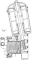
- a housing 1 of the oil cooler is provided, which is closed by a screwed-on cover 2 and sealed by means of a seal 3.
- a disk package 4 with an outer cage 5 is attached to the cover 2.
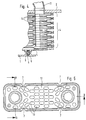
- Grooves 6 are formed in the outer cage 5, which face the disk package 4 and which engage in corresponding recesses 7 in the disks of the disk package 4.
- This arrangement of grooves 6 and recesses 7 ensures the correct position of the disks consisting of half-shells 12 in the course of the assembly of the disk package 4 in the outer cage 5, which at the same time simplifies assembly and prevents incorrect half-shells 12 from being inserted.
- On the outer sides of the outer cage 5 6 molded seals 8 are inserted into the grooves, which engage in corresponding recesses 9 in the inner walls of the housing 1.
- nozzles 10 and 11 for the inlet and outlet of cooling water are attached, which establish the connections with the corresponding inlet openings and outlet openings in the panes of the pane package 4.
- the - not shown in the drawing connections of the interior of the housing 1 with the oil filter for the inlet and the outlet of the oil are made in the housing block.
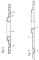
- Half-shells 12 which each form a disc of the disc package 4 in pairs, have mutually facing knobs 13 which touch one another in the assembled state of a disc and are connected to one another.
- 12 guide plates 14 are formed on the half-shells, which partially enclose the inlet openings / outlet openings of the disks and have approximately the shape of a circular cylinder segment, the central axis of which coincides approximately with the central axis of the inlet opening / outlet opening.
Landscapes
- Engineering & Computer Science (AREA)
- Physics & Mathematics (AREA)
- Thermal Sciences (AREA)
- Mechanical Engineering (AREA)
- General Engineering & Computer Science (AREA)
- Heat-Exchange Devices With Radiators And Conduit Assemblies (AREA)
- Lubrication Of Internal Combustion Engines (AREA)
Claims (9)
- Refroidisseur d'huile à plaques comportant au moins un paquet de plaques (4) qui est pourvu d'une arrivée et d'un départ, peut être traversé par les fluides et est monté dans un boîtier (1) pourvu d'une arrivée et d'un départ et pouvant être traversé par les fluides dans sa direction longitudinale, et des baguettes d'étanchéité (6, 8, 9) placées perpendiculairement à la direction longitudinale du boîtier entre les côtés du paquet de plaques et les parois opposées à ceux-ci du boîtier, caractérisé par le fait que, le paquet de plaques (4) étant traversé par de l'eau de refroidissement et le boîtier (1) traversé par de l'huile, le paquet de plaques (4) est, au moins sur ses deux côtés s'étendant dans la direction longitudinale du boîtier (1), reçu dans une cage extérieure (5) qui présente au moins deux rainures (6) dirigées vers le paquet de plaques (4) et s'étendant perpendiculairement à la direction longitudinale du boîtier (1) qui s'engagent dans des évidements correspondants (7) faits dans les bords latéraux des plaques du paquet (4), que les baguettes d'étanchéité (6, 8, 9) sont placées entre la cage extérieure (5) et le boîtier (1), que des boutons se touchant sont estampés dans les demi-coquilles (12) qui forment par paires une plaque, et que dans les orifices des plaques joints qui permettent la traversée du paquet de plaques (4) par l'eau de refroidissement sont prévus des déflecteurs (14) qui réduisent ou empêchent une traversée directe des plaques de l'orifice d'arrivée à l'orifice de départ.
- Refroidisseur d'huile selon la revendication 1, caractérisé par le fait que les baguettes d'étanchéité (8) sont engagées dans les rainures (6) sur le côté extérieur de la cage extérieure (5).
- Refroidisseur d'huile selon l'une des revendications 1 et 2, caractérisé par le fait que les déflecteurs (14) prévus dans les plaques ont à peu près la forme d'un segment de cylindre de révolution dont l'axe coïncide à peu près avec l'axe de l'orifice d'arrivée ou de départ.
- Refroidisseur d'huile selon l'une des revendications 1, 2 et 3, caractérisé par le fait que des boutons en regard (13) prévus sur les demi-coquilles (12) qui forment une plaque sont soudés entre eux.
- Refroidisseur d'huile selon l'une des revendications 1, 2, 3 et 4, caractérisé par le fait que la cage extérieure (5) est en tôle métallique soudable.
- Refroidisseur d'huile selon la revendication 5, caractérisé par le fait que la cage extérieure (5) est soudée au paquet de plaques (4).
- Refroidisseur d'huile selon l'une des revendications précédentes, caractérisé par le fait qu'entre les plaques sont prévus des déflecteurs d'huile.
- Refroidisseur d'huile selon l'une des revendications précédentes, caractérisé par le fait que les plaques, les déflecteurs (14) qui y sont prévus, la cage extérieure (5) et les déflecteurs d'huile sont constitués du même alliage d'aluminium.
- Refroidisseur d'huile selon l'une des revendications précédentes, caractérisé par le fait que le boîtier (1) fait partie d'un bloc boîtier coulé sous pression d'un filtre à huile.
Applications Claiming Priority (2)
| Application Number | Priority Date | Filing Date | Title |
|---|---|---|---|
| DE4313506 | 1993-04-24 | ||
| DE4313506A DE4313506A1 (de) | 1993-04-24 | 1993-04-24 | Ölkühler in Scheibenbauweise |
Publications (2)
| Publication Number | Publication Date |
|---|---|
| EP0622600A1 EP0622600A1 (fr) | 1994-11-02 |
| EP0622600B1 true EP0622600B1 (fr) | 1997-05-21 |
Family
ID=6486312
Family Applications (1)
| Application Number | Title | Priority Date | Filing Date |
|---|---|---|---|
| EP94103500A Expired - Lifetime EP0622600B1 (fr) | 1993-04-24 | 1994-03-08 | Refroidisseur d'huile du type à plaques empilées |
Country Status (3)
| Country | Link |
|---|---|
| EP (1) | EP0622600B1 (fr) |
| DE (2) | DE4313506A1 (fr) |
| ES (1) | ES2102708T3 (fr) |
Cited By (1)
| Publication number | Priority date | Publication date | Assignee | Title |
|---|---|---|---|---|
| KR20180036116A (ko) * | 2016-09-30 | 2018-04-09 | 한온시스템 주식회사 | 열교환기 |
Families Citing this family (18)
| Publication number | Priority date | Publication date | Assignee | Title |
|---|---|---|---|---|
| DE19519740B4 (de) * | 1995-06-02 | 2005-04-21 | Mann + Hummel Gmbh | Wärmetauscher |
| DE19544088A1 (de) * | 1995-11-27 | 1997-05-28 | Knecht Filterwerke Gmbh | Flüssigkeitsfilter mit einem Stapelscheiben-Wärmetauscher |
| DE19713883A1 (de) * | 1997-04-04 | 1998-10-08 | Knecht Filterwerke Gmbh | Lagerung eines Wärmetauschers |
| SE511072C2 (sv) * | 1997-04-22 | 1999-08-02 | Volvo Lastvagnar Ab | Kors- och motströms plattvärmeväxlare där portkanterna är försedda med sammanfogade flänsar kring en del av periferin |
| DE19717018A1 (de) * | 1997-04-23 | 1998-10-29 | Laengerer & Reich Gmbh & Co | Kühler-Filter-Anordnung |
| DE19736039B4 (de) * | 1997-08-20 | 2018-01-11 | Man Truck & Bus Ag | Brennkraftmaschine mit einem Ölmodul |
| WO2000022364A1 (fr) | 1998-10-15 | 2000-04-20 | Ebara Corporation | Echangeur thermique a plaques |
| SE519570C2 (sv) * | 2001-07-09 | 2003-03-11 | Alfa Laval Corp Ab | Värmeöverföringsplatta med flödesavgränsare; plattpaket och plattvärmeväxlare |
| SE0202747L (sv) * | 2002-09-17 | 2004-02-10 | Valeo Engine Cooling Ab | Anordning vid en plattvärmeväxlare |
| SE529769E (sv) * | 2006-04-04 | 2014-04-22 | Alfa Laval Corp Ab | Plattvärmeväxlare vilken innefattar åtminstone en förstärkningsplatta vilken är anordnad utanför en av de yttre värmeväxlarplattorna |
| DE202006011339U1 (de) * | 2006-07-20 | 2007-11-29 | Mann + Hummel Gmbh | Flüssigkeits-Wärmetauscher-Einheit |
| EP2527775A1 (fr) * | 2011-05-25 | 2012-11-28 | Alfa Laval Corporate AB | Plaque d'échangeur thermique pour échangeur thermique de type plaque et enveloppe |
| US9951995B2 (en) * | 2014-10-03 | 2018-04-24 | Dana Canada Corporation | Heat exchanger with self-retaining bypass seal |
| JP6186382B2 (ja) * | 2015-01-19 | 2017-08-23 | 株式会社日阪製作所 | プレート式熱交換器 |
| US10641559B2 (en) * | 2016-09-30 | 2020-05-05 | Hanon Systems | Heat exchanger |
| DE102019006664A1 (de) * | 2019-09-23 | 2021-03-25 | Deutz Aktiengesellschaft | Brennkraftmaschine mit im Zylinderkurbelgehäuse integriertem Ölkühler und einer Kühlwassersteuerung |
| JP7365634B2 (ja) * | 2019-10-17 | 2023-10-20 | パナソニックIpマネジメント株式会社 | 熱交換器 |
| DE102024109830B3 (de) * | 2024-04-09 | 2025-07-03 | Deere & Company | Brennkraftmaschine mit einem im wassermantel der brennkraftmaschine angeordnetem wärmetauscher |
Family Cites Families (22)
| Publication number | Priority date | Publication date | Assignee | Title |
|---|---|---|---|---|
| US2222721A (en) * | 1936-04-13 | 1940-11-26 | Gen Motors Corp | Oil cooler |
| FR958699A (fr) * | 1942-05-22 | 1950-03-17 | ||
| US2511084A (en) * | 1947-11-07 | 1950-06-13 | Young Radiator Co | Heat-exchanger core |
| DE1501492A1 (de) * | 1965-04-09 | 1969-06-26 | Daimler Benz Ag | Kuehler,insbesondere OElkuehler fuer Brennkraftmaschinen |
| DE1934193C3 (de) * | 1969-07-05 | 1979-04-26 | Farymann - Diesel Farny & Weidmann Gmbh & Co Kg, 6840 Lampertheim | Ölkühler-Ausbildung und -Befestigung zusammen mit einem ölfilter im wassergekühlten Schmierölkreislauf einer Brennkraftmaschine |
| DE2903543C2 (de) * | 1979-01-31 | 1983-03-31 | Daimler-Benz Ag, 7000 Stuttgart | Flüssigkeitswärmetauscher, insbesondere wasserdurchströmter Ölkühler für Fahrzeuge |
| SU985695A1 (ru) * | 1981-07-06 | 1982-12-30 | Белорусский институт механизации сельского хозяйства | Теплообменник |
| DE3242361C3 (de) * | 1982-11-16 | 1994-07-28 | Behr Gmbh & Co | Ölkühler in Scheibenbauweise |
| SU1244466A1 (ru) * | 1985-01-23 | 1986-07-15 | Белорусский институт механизации сельского хозяйства | Теплообменник |
| SU1267152A1 (ru) * | 1985-02-04 | 1986-10-30 | Белорусский институт механизации сельского хозяйства | Теплообменник дл системы жидкостного охлаждени двигател внутреннего сгорани |
| DE3508834A1 (de) * | 1985-03-13 | 1986-09-25 | Ing. Walter Hengst GmbH & Co KG, 4400 Münster | Oelfilter mit integriertem waermetauscher |
| US4831980A (en) * | 1987-07-13 | 1989-05-23 | Toyo Radiator Co., Ltd. | Oil cooler assembly with integrated oil filter for internal combustion engine |
| DE3815070C2 (de) * | 1988-05-04 | 1996-10-17 | Laengerer & Reich Kuehler | Kühler, insbesondere Flüssigkeitskühler |
| DE3824073C2 (de) * | 1988-07-15 | 1993-12-09 | Laengerer & Reich Kuehler | Ölkühler |
| CA1313183C (fr) * | 1989-02-24 | 1993-01-26 | Allan K. So | Echangeur de chaleur a plaques |
| CA1313182C (fr) * | 1989-02-24 | 1993-01-26 | Allan K. So | Echangeur de chaleur pour reservoir d'huile |
| DE3913100C2 (de) * | 1989-04-21 | 1994-02-17 | Laengerer & Reich Kuehler | Wärmeaustauscher, insbesondere Ölkühler |
| FR2656412B1 (fr) * | 1989-12-21 | 1995-02-17 | Valeo Thermique Moteur Sa | Echangeur de chaleur a lames, en particulier pour le refroidissement de l'huile de lubrification d'un vehicule automobile. |
| US5014775A (en) * | 1990-05-15 | 1991-05-14 | Toyo Radiator Co., Ltd. | Oil cooler and manufacturing method thereof |
| US5099912A (en) * | 1990-07-30 | 1992-03-31 | Calsonic Corporation | Housingless oil cooler |
| DE4029408C2 (de) * | 1990-09-17 | 2003-01-02 | Deutz Ag | Schmierölwärmetauscher einer Brennkraftmaschine |
| DE4128153C2 (de) * | 1991-08-24 | 1994-08-25 | Behr Gmbh & Co | Scheibenölkühler |
-
1993
- 1993-04-24 DE DE4313506A patent/DE4313506A1/de not_active Withdrawn
-
1994
- 1994-03-08 EP EP94103500A patent/EP0622600B1/fr not_active Expired - Lifetime
- 1994-03-08 ES ES94103500T patent/ES2102708T3/es not_active Expired - Lifetime
- 1994-03-08 DE DE59402802T patent/DE59402802D1/de not_active Expired - Lifetime
Cited By (1)
| Publication number | Priority date | Publication date | Assignee | Title |
|---|---|---|---|---|
| KR20180036116A (ko) * | 2016-09-30 | 2018-04-09 | 한온시스템 주식회사 | 열교환기 |
Also Published As
| Publication number | Publication date |
|---|---|
| DE59402802D1 (de) | 1997-06-26 |
| DE4313506A1 (de) | 1994-10-27 |
| EP0622600A1 (fr) | 1994-11-02 |
| ES2102708T3 (es) | 1997-08-01 |
Similar Documents
| Publication | Publication Date | Title |
|---|---|---|
| EP0622600B1 (fr) | Refroidisseur d'huile du type à plaques empilées | |
| EP1152204B1 (fr) | Echangeur de chaleur à plaques | |
| DE10347181B4 (de) | Wärmetauscher, insbesondere Ölkühler | |
| DE10082025B4 (de) | Wärmetauscher und Lötverfahren | |
| DE3319521C2 (fr) | ||
| DE69411677T2 (de) | Lamellenwärmetauscher, insbesondere Ölkühler für Kraftfahrzeug | |
| DE4313505C2 (de) | Flüssigkeitskühler mit einem durchströmbaren Scheibenpaket | |
| DE2744234B2 (de) | Plattenkondensator | |
| DE3630084C2 (fr) | ||
| DE2843423B1 (de) | OElkuehler mit scheibenaehnlichen OElkammern fuer eine Brennkraftmaschine | |
| EP0180086B1 (fr) | Refroidisseur d'huile | |
| DE19707647B4 (de) | Scheibenkühler | |
| DE20121112U1 (de) | Sammelkasten für einen Wärmeaustauscher, insbesondere an Kraftfahrzeugen | |
| DE3938253A1 (de) | Oelkuehler fuer eine brennkraftmaschine | |
| DE202016006515U1 (de) | Akkublock aus einer Vielzahl von Akkuzellen | |
| DE3020557C2 (de) | Kreuzstrom-Plattenwärmetauscher als Ölkühler für Brennkraftmaschinen, insbesondere von Kraftfahrzeugen | |
| DE2733718C2 (de) | Filterkopf für in Parallelschaltung zu einer Filterbatterie zusammensetzbare Einzelfilter | |
| DE19654365A1 (de) | Plattenwärmeübertrager | |
| DE3341361C2 (de) | Radiator, insbesondere für Klimaanlagen von Kraftfahrzeugen | |
| DE2410705A1 (de) | Kompressor | |
| DE3605825C1 (de) | Waermetauscher fuer zwei fluide Medien | |
| DE102004035448A1 (de) | Platten-Wärmetauscher | |
| EP0197169B1 (fr) | Radiateur | |
| DE19757803A1 (de) | Wärmeübertrager | |
| DE19753823A1 (de) | Plattenwärmetauscher mit integriertem Filter für die Ölkühlung |
Legal Events
| Date | Code | Title | Description |
|---|---|---|---|
| PUAI | Public reference made under article 153(3) epc to a published international application that has entered the european phase |
Free format text: ORIGINAL CODE: 0009012 |
|
| AK | Designated contracting states |
Kind code of ref document: A1 Designated state(s): DE ES FR GB |
|
| 17P | Request for examination filed |
Effective date: 19950410 |
|
| GRAG | Despatch of communication of intention to grant |
Free format text: ORIGINAL CODE: EPIDOS AGRA |
|
| 17Q | First examination report despatched |
Effective date: 19961204 |
|
| GRAH | Despatch of communication of intention to grant a patent |
Free format text: ORIGINAL CODE: EPIDOS IGRA |
|
| GRAH | Despatch of communication of intention to grant a patent |
Free format text: ORIGINAL CODE: EPIDOS IGRA |
|
| GRAA | (expected) grant |
Free format text: ORIGINAL CODE: 0009210 |
|
| AK | Designated contracting states |
Kind code of ref document: B1 Designated state(s): DE ES FR GB |
|
| REF | Corresponds to: |
Ref document number: 59402802 Country of ref document: DE Date of ref document: 19970626 |
|
| GBT | Gb: translation of ep patent filed (gb section 77(6)(a)/1977) |
Effective date: 19970613 |
|
| ET | Fr: translation filed | ||
| REG | Reference to a national code |
Ref country code: ES Ref legal event code: FG2A Ref document number: 2102708 Country of ref document: ES Kind code of ref document: T3 |
|
| PLBE | No opposition filed within time limit |
Free format text: ORIGINAL CODE: 0009261 |
|
| STAA | Information on the status of an ep patent application or granted ep patent |
Free format text: STATUS: NO OPPOSITION FILED WITHIN TIME LIMIT |
|
| 26N | No opposition filed | ||
| REG | Reference to a national code |
Ref country code: GB Ref legal event code: IF02 |
|
| PGFP | Annual fee paid to national office [announced via postgrant information from national office to epo] |
Ref country code: GB Payment date: 20130328 Year of fee payment: 20 |
|
| PGFP | Annual fee paid to national office [announced via postgrant information from national office to epo] |
Ref country code: ES Payment date: 20120321 Year of fee payment: 19 |
|
| PGFP | Annual fee paid to national office [announced via postgrant information from national office to epo] |
Ref country code: DE Payment date: 20130531 Year of fee payment: 20 |
|
| PGFP | Annual fee paid to national office [announced via postgrant information from national office to epo] |
Ref country code: FR Payment date: 20130422 Year of fee payment: 20 |
|
| REG | Reference to a national code |
Ref country code: DE Ref legal event code: R071 Ref document number: 59402802 Country of ref document: DE |
|
| REG | Reference to a national code |
Ref country code: GB Ref legal event code: PE20 Expiry date: 20140307 |
|
| PG25 | Lapsed in a contracting state [announced via postgrant information from national office to epo] |
Ref country code: GB Free format text: LAPSE BECAUSE OF EXPIRATION OF PROTECTION Effective date: 20140307 Ref country code: DE Free format text: LAPSE BECAUSE OF EXPIRATION OF PROTECTION Effective date: 20140311 |
|
| REG | Reference to a national code |
Ref country code: ES Ref legal event code: FD2A Effective date: 20140926 |
|
| PG25 | Lapsed in a contracting state [announced via postgrant information from national office to epo] |
Ref country code: ES Free format text: LAPSE BECAUSE OF EXPIRATION OF PROTECTION Effective date: 20140309 |