EP0622609A2 - Längenmessinstrument mittels sichtbarer Laserstrahlen ohne fysischen Kontakt - Google Patents
Längenmessinstrument mittels sichtbarer Laserstrahlen ohne fysischen Kontakt Download PDFInfo
- Publication number
- EP0622609A2 EP0622609A2 EP94200991A EP94200991A EP0622609A2 EP 0622609 A2 EP0622609 A2 EP 0622609A2 EP 94200991 A EP94200991 A EP 94200991A EP 94200991 A EP94200991 A EP 94200991A EP 0622609 A2 EP0622609 A2 EP 0622609A2
- Authority
- EP
- European Patent Office
- Prior art keywords
- transmitter
- laser beam
- instrument according
- measurements
- radius
- Prior art date
- Legal status (The legal status is an assumption and is not a legal conclusion. Google has not performed a legal analysis and makes no representation as to the accuracy of the status listed.)
- Pending
Links
Images

Classifications
-
- G—PHYSICS
- G01—MEASURING; TESTING
- G01B—MEASURING LENGTH, THICKNESS OR SIMILAR LINEAR DIMENSIONS; MEASURING ANGLES; MEASURING AREAS; MEASURING IRREGULARITIES OF SURFACES OR CONTOURS
- G01B11/00—Measuring arrangements characterised by the use of optical techniques
- G01B11/02—Measuring arrangements characterised by the use of optical techniques for measuring length, width or thickness
- G01B11/06—Measuring arrangements characterised by the use of optical techniques for measuring length, width or thickness for measuring thickness ; e.g. of sheet material
- G01B11/0608—Height gauges
Definitions
- the subject of the present invention is the extensible instrument with visible laser rays for the measurement of lengths without physical contact which is defined in claim 1.
- This instrument is in fact remarkable in that it comprises an extensible device at at least one of the ends of which is provided a transmitter capable of emitting, perpendicular to the axis of the extensible device, a visible laser beam which makes it possible to perform vertical measurements if the above-mentioned device is oriented vertically, horizontal measurements if it is oriented horizontally.
- the extensible device is supported on the reference plane from which it is desired to note the height at which the object in question is placed.
- the device Due to its extensibility, the device makes it possible to position the laser beam at the desired coast; at the point where the ray meets a solid body, this ray defines a clearly visible colored spot, so that the line or point sought is thus identified with precision.
- the measurement is read on the expandable device, the latter being carried out telescopically or in any other way; it is advantageously provided with a tape measure system, with graduated rulers, with electronic digital sensor or of any other known type.
- the extendable device As will be explained below, correct measurement requires that the extendable device be oriented in a perfectly vertical manner and it is for this reason that it is equipped with a precision leveling system, of a type known per se. In order to facilitate the operation, it is advantageous to fix the extensible device to a tripod or other support, for example using a clamp capable of being adjusted in different directions.
- the aiming laser beam must be oriented in a rigorously horizontal manner and for this reason it must exit from the extensible device in a direction perpendicular to the axis thereof.
- This condition can be obtained structurally during assembly of the device, or it constitutes an intrinsic characteristic due to the arrangement of the device itself, as will be better understood below.
- the emitter is rigidly fixed to the upper end of the device, this emitter being arranged and adjusted so that the laser beam is emitted in a direction perpendicular to the axis of the device.
- the extensible device By being held in a vertical position, it is the extensible device which thus determines the horizontality of the radius.
- the upper end of the extendable device comprises a self-leveling oscillating head by gravity, which is equipped with the laser beam emitter arranged so that in the rest position, the laser beam is issued in a strictly horizontal manner.
- the transmitter carried by the extendable device generates a laser beam oriented parallel to the axis of said device, being integral with the latter or rigidly linked to the fixed part of the latter, which transmitter incorporates a precision leveling system so that the emitted ray is always in a perfectly vertical plane.
- a folding prism positioned in a projecting manner so as to intercept the vertical beam and to deflect it very exactly at 90 °, so that the returned laser beam is finally oriented perfectly horizontally.
- the transmitter In the case of an oscillating head, the transmitter must, on the contrary, be arranged so that in the rest position, the laser beam is emitted vertically.
- the measuring instrument shown in fig. 1 comprises a device produced using telescopic sliding tubes or in another manner capable of making it extendable in length. At its upper end, this device 1 is rigidly provided with a head 2 equipped with a laser beam emitter, these rays being projected perpendicular to the axis of the device 1 so that an orthogonal beam can target the edge a vertical object such as 3 to measure the height thereof relative to the ground 4 against which said device 1 bears.
- the desired measurement is obtained by a simple reading on the extendable device 1, without the need for physical contact between the end of this device and the object to be measured.
- a correct reading can only be obtained on condition that the extensible device 1 is held in a strictly vertical manner, so that this device is provided with an appropriate leveling system carried out in any known manner, for example at using spirit levels or benchmarks.
- the expandable device 1 which has been illustrated in FIG. 2 carries at its upper end a head 5 of the oscillating type with self-leveling by gravity, this head being advantageously damped in its oscillations.
- the head 5 is equipped with the laser beam emitter which is arranged so that in the rest position of said head 5, the rays are emitted on the horizon.
- This arrangement allows a correct measurement of the height between the ground and the lower edge of the object 3, even if the device 1 is not kept perfectly vertical. Indeed, small defects in the verticality of the device do not generate appreciable errors between the length to be measured and the value read on said device.
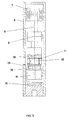
- FIG. 3 There is shown in detail in FIG. 3 a particular embodiment of the self-leveling oscillating head 5.
- This head comprises a casing 6 inside which is mounted a cross-hinged mechanism 7 or equivalent system, which supports a rod 8 on which the laser beam emitter 9 is perpendicularly mounted; a counterweight 10 permanently ensures verticality perfect rod 8 and, therefore, the precise horizontality of the laser beam from the transmitter 9.
- the counterweight 10 can be pierced with a transverse tapping 11 containing a screw 12 which makes it possible, by displacement of its mass, to compensate for any small irregularities of the oscillating crew and thus to obtain the exact horizontality of the radius laser.
- the electronic circuit 14 is designed so that the electromagnet 15 is excited during each variation of its electrical parameters, such a variation causing the modification of the distance between the sensor 13 and the oscillating counterweight 10. The electromagnet 15 then pushes the rod 16 of the core until it strikes and blocks the counterweight 10.
- the braking and damping system can of course be of another type than that described above, for example by using an optical signal which, deflected by the oscillation of the counterweight, determines variations in current in the braking electromagnet, or in an electromagnetic system controlled by variations in the magnetic field created by a permanent magnet oscillating with the counterweight.
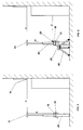
- the expandable device which has been illustrated in FIG. 4 is provided, at its movable end, with a prism 17 provided for projecting so as to intercept and deflect at 90 ° the vertical laser beam X coming from a transmitter 18 suitably placed laterally near the device itself ; under these conditions, by maintaining the device in a vertical position, it is obtained that the deflected radius Y is projected horizontally, which makes it possible to target an inaccessible point 19 and thus to make a measurement without contact by reading on the expandable device.
- the laser beam emitter 18 is securely attached to the extendable device 20, parallel to it, using a collar 21 fitted with a leveling system capable of allowing the exact vertical positioning of the laser beam X from said transmitter.
- a leveling system capable of allowing the exact vertical positioning of the laser beam X from said transmitter.
- an optical prism 17 arranged and oriented so that the X-ray is exactly deviated by 90 °, consequently horizontally.
- the prism 17 can be replaced by a clean optical pentaprism, in known manner, to always deviate by 90 ° the incident ray, independently of the relative positioning of the pentaprism with respect to this incident ray.
- the extendable device 20 operates in the same manner as in FIG. 4 with the help of another pentaprism 22 directly provided on the emitter 18 at the exit of the laser beam X.
- This pentaprism 22 generates two laser rays, namely the horizontal ray Z which is used for a fixed reference sight and the radius X1 which, oriented perfectly vertical, is intercepted by the pentaprism 23, which deflects it to form a ray Y oriented perfectly horizontally for its aiming function.
- a tripod or other suitable support 24 to which said device is linked, for example using a clamp 25 capable of being adjusted in all sense.
- the transmitter 18 it is possible to arrange the transmitter 18 separately from the device 20, this transmitter being supported by an independent adjustable clamp, it being observed that it is essential that the axis of the device 20 is always parallel to the axis of the vertical laser beam.
- the pentaprism is mounted on a support capable of being oriented by hand or with the aid of a motor.
Landscapes
- Physics & Mathematics (AREA)
- General Physics & Mathematics (AREA)
- Length Measuring Devices By Optical Means (AREA)
Applications Claiming Priority (2)
| Application Number | Priority Date | Filing Date | Title |
|---|---|---|---|
| ITVI930061 | 1993-04-20 | ||
| ITVI930061A IT1270349B (it) | 1993-04-20 | 1993-04-20 | Dispositivo allungabile a raggi laser visibili per misure di lunghezza senza contatto fisico |
Publications (2)
| Publication Number | Publication Date |
|---|---|
| EP0622609A2 true EP0622609A2 (de) | 1994-11-02 |
| EP0622609A3 EP0622609A3 (de) | 1995-02-01 |
Family
ID=11425188
Family Applications (1)
| Application Number | Title | Priority Date | Filing Date |
|---|---|---|---|
| EP94200991A Pending EP0622609A3 (de) | 1993-04-20 | 1994-04-12 | Längenmessinstrument mittels sichtbarer Laserstrahlen ohne fysischen Kontakt. |
Country Status (2)
| Country | Link |
|---|---|
| EP (1) | EP0622609A3 (de) |
| IT (1) | IT1270349B (de) |
Cited By (3)
| Publication number | Priority date | Publication date | Assignee | Title |
|---|---|---|---|---|
| FR2745900A1 (fr) * | 1996-03-08 | 1997-09-12 | R B M S A | Dispositif pour mesurer la hauteur totale d'un chargement d'un vehicule automobile |
| CN100462679C (zh) * | 2005-12-27 | 2009-02-18 | 厦门大学 | 滩涂高程测量仪及其测量方法 |
| US7841094B2 (en) | 2009-01-27 | 2010-11-30 | Trimble Kaiserslautern Gmbh | Optical instrument with angle indicator and method for operating the same |
Family Cites Families (4)
| Publication number | Priority date | Publication date | Assignee | Title |
|---|---|---|---|---|
| US3936197A (en) * | 1974-05-06 | 1976-02-03 | Laser Alignment, Inc. | Self-leveling laser assembly |
| US4247809A (en) * | 1979-01-23 | 1981-01-27 | Agl Corporation | Electrical levelling system for laser beam |
| US4770480A (en) * | 1986-05-12 | 1988-09-13 | Spectra-Physics, Inc. | Apparatus and method for providing multiple reference laser beams |
| DE9103027U1 (de) * | 1991-03-13 | 1991-06-13 | Z-Laser Optoelektronik GmbH, 7800 Freiburg | Hilfsgerät zur optischen Darstellung von Linien |
-
1993
- 1993-04-20 IT ITVI930061A patent/IT1270349B/it active IP Right Grant
-
1994
- 1994-04-12 EP EP94200991A patent/EP0622609A3/de active Pending
Cited By (3)
| Publication number | Priority date | Publication date | Assignee | Title |
|---|---|---|---|---|
| FR2745900A1 (fr) * | 1996-03-08 | 1997-09-12 | R B M S A | Dispositif pour mesurer la hauteur totale d'un chargement d'un vehicule automobile |
| CN100462679C (zh) * | 2005-12-27 | 2009-02-18 | 厦门大学 | 滩涂高程测量仪及其测量方法 |
| US7841094B2 (en) | 2009-01-27 | 2010-11-30 | Trimble Kaiserslautern Gmbh | Optical instrument with angle indicator and method for operating the same |
Also Published As
| Publication number | Publication date |
|---|---|
| ITVI930061A1 (it) | 1994-10-20 |
| IT1270349B (it) | 1997-05-05 |
| EP0622609A3 (de) | 1995-02-01 |
| ITVI930061A0 (it) | 1993-04-20 |
Similar Documents
| Publication | Publication Date | Title |
|---|---|---|
| CH623502A5 (de) | ||
| FR2631438A1 (fr) | Procede de positionnement d'un objet par rapport a un plan, procede de mesure de longueur et dispositifs de mise en oeuvre de ces procedes | |
| FR2551860A1 (fr) | Installation pour la determination des coordonnees spatiales d'un point d'une piece, notamment pour le controle d'un outillage tel qu'un outillage de soudage de carrosserie de vehicule automobile | |
| EP0053065B1 (de) | Vorrichtung zum Überwachen der Geometrie von Fahrzeugrädern | |
| JPS5953484B2 (ja) | 地形上の諸点を測量するための水準測量装置 | |
| JP4323046B2 (ja) | 器械の高さ測定装置付き測量器械 | |
| FR2553190A1 (fr) | Procede et dispositif pour mesurer un niveau de remplissage | |
| EP0154568A1 (de) | Winkelkodiergerät zur Kodierung des Zenithwinkels zwischen einer vorgegebenen variablen Richtung und der Vertikalen, insbesondere für einen Theodoliten | |
| EP0622609A2 (de) | Längenmessinstrument mittels sichtbarer Laserstrahlen ohne fysischen Kontakt | |
| EP0619470A1 (de) | Vorrichtung zur horizontalen Projektion eines Laserstrahles | |
| EP1327854A1 (de) | Winkelpositionierungsvorrichtung, Keil und Verwendung der Vorrichtung | |
| FR2512576A1 (fr) | Systeme de guidage lineaire d'un dispositif de balayage | |
| JPH0540072A (ja) | 鏡面の測定装置 | |
| US20060064887A1 (en) | Universal laser beam generating device | |
| US4344234A (en) | Apparatus and method for measuring rear wheel toe with respect to chassis centerline | |
| FR2915278A1 (fr) | Systeme de releve des hauteurs comprenant une regle telescopique a deux extremites cooperant avec un faisceau optique a balayage dans un plan horizontal. | |
| JPH07146140A (ja) | 勾配測定装置 | |
| JP3744639B2 (ja) | 測距測角儀の機械高測定方法及び機械高測定装置 | |
| EP0048688B1 (de) | Verfahren zur optischen Detektion und/oder zum Messen einer Deformation und/oder einer Versetzung eines Objektes oder eines Objektteiles, Vorrichtung für die Ausführung dieses Verfahrens und Anwendung des Verfahrens | |
| JP2001027527A (ja) | 傾斜測定装置 | |
| EP0484310B1 (de) | Vorrichtung zum Messen der Rauhigkeit eines sich bewegenden Metallerzeugnisses | |
| CH375909A (fr) | Dispositif de détermination de la position d'un organe mobile de machine | |
| FR2612628A1 (fr) | Dispositif de mesure par interferometrie laser | |
| CN100465603C (zh) | 张力计 | |
| CH267992A (fr) | Balance automatique à indication automatique du prix de la marchandise pesée. |
Legal Events
| Date | Code | Title | Description |
|---|---|---|---|
| PUAI | Public reference made under article 153(3) epc to a published international application that has entered the european phase |
Free format text: ORIGINAL CODE: 0009012 |
|
| AK | Designated contracting states |
Kind code of ref document: A2 Designated state(s): AT BE CH DE ES FR GB GR IT LI NL PT SE |
|
| PUAL | Search report despatched |
Free format text: ORIGINAL CODE: 0009013 |
|
| AK | Designated contracting states |
Kind code of ref document: A3 Designated state(s): AT BE CH DE ES FR GB GR IT LI NL PT SE |
|
| 17P | Request for examination filed |
Effective date: 19950707 |
|
| STAA | Information on the status of an ep patent application or granted ep patent |
Free format text: STATUS: EXAMINATION IS IN PROGRESS |
|
| 17Q | First examination report despatched |
Effective date: 19961210 |