EP0622628A2 - Capteur pour la mesure de l'humidité des matériaux - Google Patents
Capteur pour la mesure de l'humidité des matériaux Download PDFInfo
- Publication number
- EP0622628A2 EP0622628A2 EP94106488A EP94106488A EP0622628A2 EP 0622628 A2 EP0622628 A2 EP 0622628A2 EP 94106488 A EP94106488 A EP 94106488A EP 94106488 A EP94106488 A EP 94106488A EP 0622628 A2 EP0622628 A2 EP 0622628A2
- Authority
- EP
- European Patent Office
- Prior art keywords
- probe
- conductors
- measuring
- signal
- medium
- Prior art date
- Legal status (The legal status is an assumption and is not a legal conclusion. Google has not performed a legal analysis and makes no representation as to the accuracy of the status listed.)
- Withdrawn
Links
- 239000000523 sample Substances 0.000 title claims abstract description 40
- 239000000463 material Substances 0.000 title claims abstract description 14
- 239000004020 conductor Substances 0.000 claims description 37
- 238000005259 measurement Methods 0.000 claims description 4
- 239000011248 coating agent Substances 0.000 claims description 3
- 238000000576 coating method Methods 0.000 claims description 3
- 230000035945 sensitivity Effects 0.000 description 7
- 238000000034 method Methods 0.000 description 5
- 238000004804 winding Methods 0.000 description 3
- 238000013461 design Methods 0.000 description 2
- 238000011088 calibration curve Methods 0.000 description 1
- 239000003990 capacitor Substances 0.000 description 1
- 230000001419 dependent effect Effects 0.000 description 1
- 238000010291 electrical method Methods 0.000 description 1
- 238000011156 evaluation Methods 0.000 description 1
- 230000005284 excitation Effects 0.000 description 1
- 239000011253 protective coating Substances 0.000 description 1
- 239000010802 sludge Substances 0.000 description 1
- 239000000126 substance Substances 0.000 description 1
- 238000012549 training Methods 0.000 description 1
- XLYOFNOQVPJJNP-UHFFFAOYSA-N water Substances O XLYOFNOQVPJJNP-UHFFFAOYSA-N 0.000 description 1
Images

Classifications
-
- G—PHYSICS
- G01—MEASURING; TESTING
- G01N—INVESTIGATING OR ANALYSING MATERIALS BY DETERMINING THEIR CHEMICAL OR PHYSICAL PROPERTIES
- G01N27/00—Investigating or analysing materials by the use of electric, electrochemical, or magnetic means
- G01N27/02—Investigating or analysing materials by the use of electric, electrochemical, or magnetic means by investigating impedance
- G01N27/22—Investigating or analysing materials by the use of electric, electrochemical, or magnetic means by investigating impedance by investigating capacitance
- G01N27/223—Investigating or analysing materials by the use of electric, electrochemical, or magnetic means by investigating impedance by investigating capacitance for determining moisture content, e.g. humidity
-
- G—PHYSICS
- G01—MEASURING; TESTING
- G01N—INVESTIGATING OR ANALYSING MATERIALS BY DETERMINING THEIR CHEMICAL OR PHYSICAL PROPERTIES
- G01N27/00—Investigating or analysing materials by the use of electric, electrochemical, or magnetic means
- G01N27/02—Investigating or analysing materials by the use of electric, electrochemical, or magnetic means by investigating impedance
- G01N27/22—Investigating or analysing materials by the use of electric, electrochemical, or magnetic means by investigating impedance by investigating capacitance
- G01N27/226—Construction of measuring vessels; Electrodes therefor
Definitions
- the invention relates to a device for determining the material moisture of a medium by determining its dielectric constant, which medium forms the dielectric of a measuring line, with the aid of a signal generator that feeds a pulse-shaped signal into one end of the measuring line and a receiver that at the same end signal received at the other end of the measuring line, and a device for measuring the time which elapses between the start of the feeding of the signal and the arrival of the reflected signal.
- the material moisture can be measured by means of a dielectric constant determination.
- a dielectric constant determination There is a monotonous unambiguous relationship between the dielectric constant of a medium and its moisture content.
- the dielectric constant can be determined by means of an arrangement in which the medium to be measured is brought between two plates, via the capacitance of the arrangement. Here, however, either measurement problems or cumbersome sizes of the capacitor plates occur.
- the conductor forms a finite-length open line of known geometry.
- An electrical pulse is introduced at the electrical connection and the time until the return of the echo from the end of the line is measured. It is known to design the line in the form of two parallel spikes that are inserted into the material to be measured. From the duration of the echo, one can draw conclusions about the dielectric constant of the medium and further about the water content.
- FIG. 1 An exemplary embodiment of the echo method is described in FIG. 1.
- a voltage rise with the steepest possible signal edge is generated by a signal source K1, which is connected with a negligible length of the supply line.
- the internal resistance of the signal source K1 corresponds to the characteristic impedance of the open line 7a, 7b, insofar as this can be simulated with simple means for the center of the measuring range. In this way, at the connection between the output of the signal source K1 and the measuring line 7a, 7b, with a suitable measuring range, reflections which are not very disturbing arise. Full reflection occurs at the open end of the measuring line 7a, 7b.
- a threshold signal K2 which compares the voltage at the electrical connection of the measuring rods 7a, 7b with predetermined values, generates a gate signal for a counter 5, which counts only in the time between the start of excitation and the arrival of the echo pulses of a free-running oscillator 3 .
- the counter 5 is in turn connected to an evaluation and display device 6.
- the start of the gate opening can advantageously also be initiated with a delay by the signal source K1, so that an opening only takes place after the reflection at the connection of the measuring rods has passed.
- the variation in the material moisture changes the dielectric constant and thus the capacitance of the medium that surrounds the rods of the measuring line 7a, 7b.
- the geometric data of the measuring line 7a, 7b are constant, this results in a known relationship between the material moisture and the measured transit time of the echo. This can be given by an equation or a calibration curve.
- the measuring rods 7a, 7b must be very long if one wants to achieve a high sensitivity of the arrangement. Because of the length of the measuring rods 7a, 7b, the handling of the arrangement is often not easy.
- the measuring line is designed as a probe which has a body which has electrical conductors in the area of its surface.
- the configuration of the measuring line according to the invention makes it easy to handle, even with a relatively long length of the electrical conductor.
- the measuring lines are now no longer difficult to handle long rods, but are located on the circumference of a body, depending on the stability or manageability of the measuring line Requirements can be trained.
- a cylindrical body has proven to be particularly advantageous.
- the measuring line can loop around the body in a spiral or run meandering on its surface. With such an arrangement, the effective length of the measuring line can be made very large without the probe taking on too large geometrical dimensions.
- Another embodiment of the invention provides that the probe is provided with an insulating coating, which has a constant dielectric constant. This protects the measuring line from mechanical damage without falsifying the measurement result.
- a special embodiment of the invention provides that the connections of the electrical conductors extend into the interior of the body. This can be done in that bores extend radially inward from the conductors, through which electrical conductors such as wire are then guided.
- the connections inside the body are expediently guided axially outwards.
- the body can be hollow or full inside. If appropriate, a hollow body may be filled with a material other than the body. This can further improve the sensitivity and accuracy of the probe.
- a tube can be inserted into the medium, the inside diameter of which is slightly larger than the outside diameter of the probe.
- the probe is then inserted into the tube.
- the probe can be quickly removed from the medium, for example to be exchanged for another; on the other hand, this arrangement also makes it possible, by moving the probe, to measure the moisture content at different points in the medium without great effort.
- Another embodiment of the invention provides that the probe tapers to one end. This allows the probe to be inserted directly into the medium to be measured without using a tube.
- the protective coating made of a material with a constant dielectric constant is very advantageous.
- the body is tubular and has mounting flanges on its end faces. This advantageously makes it possible to install the probe in a pipeline and to convey the medium to be measured through the probe. This is particularly advantageous if you want to determine the moisture content of sludge or the like.
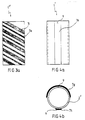
- the cylindrical probe 2 shows a cylindrical probe 1, which has meandering electrical conductors 7c, 7d on its body 2.
- the electrical conductors 7c and 7d run at a distance from one another which depends on the medium to be measured.
- the meandering arrangement increases the length of the electrical line 7c, 7d to a multiple of the length of the rods, the length of which would correspond to the height of the probe.
- the length of the measuring line increased in this way greatly increases the sensitivity of the arrangement.
- Fig. 3 shows a cylindrical probe 1 ', the lower end 8 tapers. This makes it very easy to insert into a medium whose moisture content is to be measured.
- the body 2 'of the probe 1' has on its surface helical electrical conductors 7e, 7f. This has also greatly increased the effective length of the measuring line.
- the probe is provided with an insulating coating of constant dielectric constant.
- 3a also shows a cylindrical probe 1 '''in which the electrical conductors 7i, 7k are of different widths.
- the sensitivity of the probe and its accuracy are greatly increased by the different width of the electrical conductors.
- the spiral winding is particularly advantageous if the probe is inserted into the measuring medium by means of a tube. The spiral winding compensates for an error caused by the fact that the surface of the probe is not at the same distance from the pipe wall and thus from the measuring medium. If a winding is very close to the pipe wall, this is compensated for by the larger distance on the opposite side.
- a cylindrical probe 2 ′′ can be seen which has two electrical conductors 7g, 7h on its body 2 ′′.
- the two conductors 7g, 7h run parallel to one another in the axial direction.
- the length of the ladder almost corresponds to the length of the cylindrical body 2 ′′.
- the one electrical body 7g extends in the direction of the circumference over 180 °, that is to say it almost covers half of the surface of the body 2 ′′.
- the other electrical conductor 7h is arranged radially opposite one electrical conductor 7g. With this arrangement, the distance between the outer edges of the long sides of the electrical conductors 7g, 7h is equal to one another.
- the cylindrical body 2 '' is hollow on the inside. Openings 9 extend through the wall of the body 2 ′′ in the region of the electrical conductors 7g, 7h. The connections of the electrical conductors can be guided into the interior of the body 2 ′′ through these openings.
- the body 2; 2 '; 2 '' can also have a different shape depending on the requirements. It can be triangular, square, hexagonal or oval. Furthermore, the body 2; 2 '; 2 '' hollow inside. Training as a record is also possible. It should be noted, however, that there are electrical conductors at a distance in the area of the surface, the course of which is aimed at achieving maximum sensitivity.
Landscapes
- Chemical & Material Sciences (AREA)
- Chemical Kinetics & Catalysis (AREA)
- Electrochemistry (AREA)
- Physics & Mathematics (AREA)
- Health & Medical Sciences (AREA)
- Life Sciences & Earth Sciences (AREA)
- Analytical Chemistry (AREA)
- Biochemistry (AREA)
- General Health & Medical Sciences (AREA)
- General Physics & Mathematics (AREA)
- Immunology (AREA)
- Pathology (AREA)
- Investigating Or Analyzing Materials By The Use Of Electric Means (AREA)
- Measurement Of Resistance Or Impedance (AREA)
Applications Claiming Priority (4)
| Application Number | Priority Date | Filing Date | Title |
|---|---|---|---|
| DE9306441U | 1993-04-29 | ||
| DE9306441U DE9306441U1 (de) | 1993-04-29 | 1993-04-29 | Sonde für Materialfeuchtesensor |
| DE4334649 | 1993-10-12 | ||
| DE4334649A DE4334649C2 (de) | 1993-04-29 | 1993-10-12 | Sonde für Materialfeuchtesensor |
Publications (2)
| Publication Number | Publication Date |
|---|---|
| EP0622628A2 true EP0622628A2 (fr) | 1994-11-02 |
| EP0622628A3 EP0622628A3 (fr) | 1996-07-24 |
Family
ID=25930326
Family Applications (1)
| Application Number | Title | Priority Date | Filing Date |
|---|---|---|---|
| EP94106488A Withdrawn EP0622628A3 (fr) | 1993-04-29 | 1994-04-26 | Capteur pour la mesure de l'humidité des matériaux. |
Country Status (3)
| Country | Link |
|---|---|
| US (1) | US5459403A (fr) |
| EP (1) | EP0622628A3 (fr) |
| DE (1) | DE4334649C2 (fr) |
Cited By (12)
| Publication number | Priority date | Publication date | Assignee | Title |
|---|---|---|---|---|
| EP0911628A1 (fr) * | 1997-10-10 | 1999-04-28 | GSF-Forschungszentrum für Umwelt und Gesundheit GmbH | Capteur pour la détermination de la teneur en eau |
| DE102019119281A1 (de) * | 2019-07-16 | 2021-01-21 | Endress+Hauser SE+Co. KG | Messgerät zur Bestimmung eines Dielektrizitätswert-Profils |
| DE102019121995A1 (de) * | 2019-08-15 | 2021-02-18 | Endress+Hauser SE+Co. KG | Messgerät zur Bestimmung eines Dielektrizitätswertes |
| WO2021052706A1 (fr) | 2019-09-16 | 2021-03-25 | Endress+Hauser SE+Co. KG | Dispositif de mesure pour déterminer une valeur diélectrique |
| DE102019127961A1 (de) * | 2019-10-16 | 2021-04-22 | Imko Micromodultechnik Gmbh | Verfahren zur Überprüfung der Funktionstüchtigkeit von Mess-Systemen |
| DE102019133259A1 (de) * | 2019-12-05 | 2021-06-10 | Imko Micromodultechnik Gmbh | TDR-basiertes Dielektrizitätswert-Messgerät |
| DE102020100861A1 (de) | 2020-01-15 | 2021-07-15 | Endress+Hauser SE+Co. KG | Messgerät zur Bestimmung eines Dielektrizitätswertes |
| DE102020103191A1 (de) | 2020-02-07 | 2021-08-12 | Imko Micromodultechnik Gmbh | Pulslaufzeit-basiertes Messgerät zur Leitfähigkeitsmessung |
| WO2022033831A1 (fr) | 2020-08-11 | 2022-02-17 | Endress+Hauser SE+Co. KG | Dispositif de mesure de constante diélectrique |
| WO2022033829A1 (fr) | 2020-08-11 | 2022-02-17 | Endress+Hauser SE+Co. KG | Dispositif de mesure de constante diélectrique compensée en température |
| DE102021112183A1 (de) | 2021-05-10 | 2022-11-10 | Endress+Hauser SE+Co. KG | Mess-System zur Massefluss-Messung |
| DE102021133787A1 (de) | 2021-12-20 | 2023-06-22 | Endress+Hauser SE+Co. KG | Detektion von Fremdkörpern in fließenden Messmedien |
Families Citing this family (26)
| Publication number | Priority date | Publication date | Assignee | Title |
|---|---|---|---|---|
| US5801537A (en) * | 1995-08-30 | 1998-09-01 | Purdue Research Foundation Office Of Technology Transfer | Method and apparatus for measuring in-place soil density and moisture content |
| US5648724A (en) * | 1996-02-08 | 1997-07-15 | U.S. Army Corps Of Engineers As Represented By The Secretary Of The Army | Metallic time-domain reflectometry roof moisture sensor |
| US5818340A (en) * | 1996-03-25 | 1998-10-06 | The United States Of America As Represented By The Secretary Of The Army | Roof moisture sensing system and method for determining presence of moisture in a roof stucture |
| US5898308A (en) * | 1997-09-26 | 1999-04-27 | Teleflex Incorporated | Time-based method and device for determining the dielectric constant of a fluid |
| DE19833331C2 (de) * | 1998-07-24 | 2001-02-15 | Karlsruhe Forschzent | Feuchtesensor für Schichten |
| US6215317B1 (en) | 1999-04-27 | 2001-04-10 | Purdue Research Foundation | Method and apparatus for measuring in-place density and moisture content |
| US6104298A (en) * | 1999-10-15 | 2000-08-15 | The United States Of America As Represented By The Secretary Of The Army | Roof moisture detection assembly |
| FI111298B (fi) * | 1999-11-16 | 2003-06-30 | Delfin Technologies Ltd | Menetelmä ihon kosteuden mittaamiseksi ja laite menetelmän soveltamiseksi |
| CA2310417C (fr) | 2000-05-30 | 2010-02-23 | Esi Environmental Sensors Inc. | Capteur de fluide |
| US6904789B2 (en) * | 2001-07-13 | 2005-06-14 | Decagon Devices, Inc. | Moisture detection apparatus and method |
| DE20206903U1 (de) * | 2002-04-30 | 2003-09-04 | Imko Intelligente Micromodule Köhler GmbH, 76275 Ettlingen | Vorrichtung zur Bestimmung der Feuchtigkeit eines Untergrundes |
| DE10219510B4 (de) * | 2002-04-30 | 2004-05-06 | imko Intelligente Micromodule Köhler GmbH | Verfahren zur Bestimmung der Feuchtigkeit eines Untergrundes |
| US20050127925A1 (en) * | 2003-12-10 | 2005-06-16 | Staples Peter E. | Moisture sensor |
| GB0427659D0 (en) * | 2004-12-17 | 2005-01-19 | Delta T Devices Ltd | Moisture content sensor and related methods |
| US7806585B2 (en) * | 2007-06-22 | 2010-10-05 | Decagon Devices, Inc. | Apparatus, method, and system for measuring water activity and weight |
| DE102009011278B4 (de) | 2009-03-05 | 2017-04-20 | Imko Micromodultechnik Gmbh | Sonde sowie Vorrichtung zur Ermittlung der Materialfeuchte oder Leitfähigkeit eines Mediums |
| DE102010001361A1 (de) * | 2010-01-29 | 2011-08-04 | Deutsches Zentrum für Luft- und Raumfahrt e.V., 51147 | Elektrodenanordnung und Latentwärmespeicher |
| RU2571301C2 (ru) * | 2013-09-23 | 2015-12-20 | Олег Креонидович Сизиков | Способ измерения физических параметров материала |
| US9909987B1 (en) | 2014-07-30 | 2018-03-06 | Transcend Engineering and Technology, LLC | Systems, methods, and software for determining spatially variable distributions of the dielectric properties of a material |
| US9970969B1 (en) | 2014-08-26 | 2018-05-15 | Transcend Engineering and Technology, LLC | Systems, methods, and software for determining spatially variable distributions of the dielectric properties of a heterogeneous material |
| CN106018500B (zh) * | 2016-08-01 | 2019-02-22 | 清华大学深圳研究生院 | 一种电容传感器及测量系统 |
| CN112236672A (zh) * | 2018-05-09 | 2021-01-15 | 艾姆克微型模块技术有限责任公司 | 用于确定介电常数的tdr测量装置 |
| DE102018111944A1 (de) * | 2018-05-17 | 2019-11-21 | Endress+Hauser SE+Co. KG | Messgerät zur Bestimmung eines Dielektrizitätswertes |
| CN110398517A (zh) * | 2019-06-20 | 2019-11-01 | 浙江大学城市学院 | 微型螺旋式原位连续贯入式tdr探头装置 |
| CN112683928A (zh) * | 2020-12-31 | 2021-04-20 | 浙大城市学院 | 一种微型tdr土壤含水量测定探头 |
| WO2025231176A1 (fr) * | 2024-04-30 | 2025-11-06 | Koliada, Llc | Système de capteurs de temps de transit de front d'onde de tension |
Family Cites Families (7)
| Publication number | Priority date | Publication date | Assignee | Title |
|---|---|---|---|---|
| US2373846A (en) * | 1941-08-02 | 1945-04-17 | Olken Hyman | Method and apparatus for moisture measurement of materials |
| US3105214A (en) * | 1959-02-25 | 1963-09-24 | Univ California | Moisture measuring apparatus |
| BE792234A (fr) * | 1971-12-03 | 1973-03-30 | Liggett & Myers Inc | Procedes et appareils pour determiner la teneur en humidite de tabac |
| US3774238A (en) * | 1971-12-09 | 1973-11-20 | Spearhead Inc | Three-terminal capacitive apparatus for remotely responding to a condition or dielectric properties of a material |
| US3789296A (en) * | 1972-06-12 | 1974-01-29 | P Caruso | Moisture monitor system |
| US5212453A (en) * | 1990-08-03 | 1993-05-18 | Imko Micromodultechnik Gmbh | Pulse echo method and apparatus for measuring the moisture content of materials |
| ES2041482T3 (es) * | 1990-10-02 | 1993-11-16 | Imko Intelligente Micromodule Kohler Gmbh | Medida de humedad de materiales. |
-
1993
- 1993-10-12 DE DE4334649A patent/DE4334649C2/de not_active Expired - Fee Related
-
1994
- 1994-04-26 EP EP94106488A patent/EP0622628A3/fr not_active Withdrawn
- 1994-05-03 US US08/238,004 patent/US5459403A/en not_active Expired - Lifetime
Cited By (21)
| Publication number | Priority date | Publication date | Assignee | Title |
|---|---|---|---|---|
| EP0911628A1 (fr) * | 1997-10-10 | 1999-04-28 | GSF-Forschungszentrum für Umwelt und Gesundheit GmbH | Capteur pour la détermination de la teneur en eau |
| DE102019119281A1 (de) * | 2019-07-16 | 2021-01-21 | Endress+Hauser SE+Co. KG | Messgerät zur Bestimmung eines Dielektrizitätswert-Profils |
| US11774477B2 (en) | 2019-08-15 | 2023-10-03 | Endress+Hauser SE+Co. KG | Measuring device for determining a dielectric constant comprising an electrically conductive arrangement electrically contacts two waveguides with one another |
| DE102019121995A1 (de) * | 2019-08-15 | 2021-02-18 | Endress+Hauser SE+Co. KG | Messgerät zur Bestimmung eines Dielektrizitätswertes |
| WO2021028130A1 (fr) | 2019-08-15 | 2021-02-18 | Endress+Hauser SE+Co. KG | Dispositif de mesure permettant de déterminer une constante diélectrique |
| US12253475B2 (en) | 2019-09-16 | 2025-03-18 | Endress+Hauser SE+Co. KG | Measuring device for determining a dielectric value |
| WO2021052706A1 (fr) | 2019-09-16 | 2021-03-25 | Endress+Hauser SE+Co. KG | Dispositif de mesure pour déterminer une valeur diélectrique |
| CN114502966B (zh) * | 2019-09-16 | 2024-12-10 | 恩德莱斯和豪瑟尔欧洲两合公司 | 用于确定介电值的测量装置 |
| DE102019124825B4 (de) | 2019-09-16 | 2024-03-07 | Endress+Hauser SE+Co. KG | Messgerät zur Bestimmung eines Dielelektrizitätswertes |
| CN114502966A (zh) * | 2019-09-16 | 2022-05-13 | 恩德莱斯和豪瑟尔欧洲两合公司 | 用于确定介电值的测量装置 |
| DE102019127961A1 (de) * | 2019-10-16 | 2021-04-22 | Imko Micromodultechnik Gmbh | Verfahren zur Überprüfung der Funktionstüchtigkeit von Mess-Systemen |
| DE102019133259A1 (de) * | 2019-12-05 | 2021-06-10 | Imko Micromodultechnik Gmbh | TDR-basiertes Dielektrizitätswert-Messgerät |
| DE102020100861A1 (de) | 2020-01-15 | 2021-07-15 | Endress+Hauser SE+Co. KG | Messgerät zur Bestimmung eines Dielektrizitätswertes |
| DE102020103191A1 (de) | 2020-02-07 | 2021-08-12 | Imko Micromodultechnik Gmbh | Pulslaufzeit-basiertes Messgerät zur Leitfähigkeitsmessung |
| DE102020121154A1 (de) | 2020-08-11 | 2022-02-17 | Endress+Hauser SE+Co. KG | Dielektrizitätswert-Messgerät |
| DE102020121151A1 (de) | 2020-08-11 | 2022-02-17 | Endress+Hauser SE+Co. KG | Temperaturkompensiertes Dielektrizitätswert-Messgerät |
| WO2022033829A1 (fr) | 2020-08-11 | 2022-02-17 | Endress+Hauser SE+Co. KG | Dispositif de mesure de constante diélectrique compensée en température |
| WO2022033831A1 (fr) | 2020-08-11 | 2022-02-17 | Endress+Hauser SE+Co. KG | Dispositif de mesure de constante diélectrique |
| DE102021112183A1 (de) | 2021-05-10 | 2022-11-10 | Endress+Hauser SE+Co. KG | Mess-System zur Massefluss-Messung |
| DE102021133787A1 (de) | 2021-12-20 | 2023-06-22 | Endress+Hauser SE+Co. KG | Detektion von Fremdkörpern in fließenden Messmedien |
| WO2023117260A1 (fr) | 2021-12-20 | 2023-06-29 | Endress+Hauser SE+Co. KG | Détection de corps étrangers dans des milieux mesurés en écoulement |
Also Published As
| Publication number | Publication date |
|---|---|
| DE4334649A1 (de) | 1994-11-03 |
| EP0622628A3 (fr) | 1996-07-24 |
| DE4334649C2 (de) | 1995-02-23 |
| US5459403A (en) | 1995-10-17 |
Similar Documents
| Publication | Publication Date | Title |
|---|---|---|
| DE4334649C2 (de) | Sonde für Materialfeuchtesensor | |
| DE2242723C2 (de) | Vorrichtung zur Niveamessung | |
| DE69712759T2 (de) | Wirbelstromprüftechnik | |
| DE2551968C3 (de) | Magnetsensor | |
| WO2019214924A1 (fr) | Dispositif de mesure tdr pour déterminer les constantes diélectriques | |
| DE69422002T2 (de) | Dämpfungseinrichtung für einen Ultraschallflüssigkeitsniveauindikator | |
| DE69524553T2 (de) | Hochauflösende Dickenmessung mit Ultraschall | |
| DE2148976B2 (fr) | ||
| EP3447456A1 (fr) | Appareil de mesure de niveau de remplissage tdr et procédé de fonctionnement d'un appareil de mesure de niveau de remplissage tdr | |
| DE4312813C2 (de) | Anordnung zur kapazitiven Füllstandsmessung | |
| DE2819731A1 (de) | Anordnung zur kapazitiven fuellstandsmessung in einem behaelter | |
| DE3004870C2 (de) | Meßelektrode für magnetische Durchflußmesser | |
| DE4124640A1 (de) | Rohrleitungssystem | |
| EP0927877B1 (fr) | Dispositif de mesure pour une jauge carburant | |
| EP0942291A2 (fr) | Dispositif de mesure de la capacité de conducteurs électriques | |
| DE2120451A1 (de) | Verfahren zum Messen des Abstandes zwischen einer Meßstelle und einer Bezugs flache eines Meßobjekts sowie Meßgerat zum Durchfuhren des Verfahrens | |
| DE19503017C2 (de) | Schneeprofilmeßsonde | |
| DE10133692A1 (de) | Verfahren und Sensor zur Füllstandsmessung einer Flüssigkeit in einem Behälter | |
| DE9306441U1 (de) | Sonde für Materialfeuchtesensor | |
| DE102004035757B3 (de) | Anordnung zur Bestimmung der Höhe eines Flüssigkeitsstandes | |
| DE3504609C2 (fr) | ||
| DE2210297A1 (de) | Kontinuierlicher fuellstandsmesser fuer elektrisch leitende fluessigkeiten | |
| DE1473864C3 (de) | Vorrichtung zur Bestimmung der Achskrümmung eines langgestreckten, metallisch umkleideten Hohlraumes | |
| DE1927330A1 (de) | Gemischdurchflussanalysator | |
| EP3150864A1 (fr) | Dispositif et procede de determination de position d'un piston de verin |
Legal Events
| Date | Code | Title | Description |
|---|---|---|---|
| PUAI | Public reference made under article 153(3) epc to a published international application that has entered the european phase |
Free format text: ORIGINAL CODE: 0009012 |
|
| AK | Designated contracting states |
Kind code of ref document: A2 Designated state(s): AT CH DE ES FR GB IT LI |
|
| PUAL | Search report despatched |
Free format text: ORIGINAL CODE: 0009013 |
|
| AK | Designated contracting states |
Kind code of ref document: A3 Designated state(s): AT CH DE ES FR GB IT LI |
|
| STAA | Information on the status of an ep patent application or granted ep patent |
Free format text: STATUS: THE APPLICATION IS DEEMED TO BE WITHDRAWN |
|
| 18D | Application deemed to be withdrawn |
Effective date: 19970125 |