EP0622660B1 - Vitrage électrochrome - Google Patents
Vitrage électrochrome Download PDFInfo
- Publication number
- EP0622660B1 EP0622660B1 EP93401112A EP93401112A EP0622660B1 EP 0622660 B1 EP0622660 B1 EP 0622660B1 EP 93401112 A EP93401112 A EP 93401112A EP 93401112 A EP93401112 A EP 93401112A EP 0622660 B1 EP0622660 B1 EP 0622660B1
- Authority
- EP
- European Patent Office
- Prior art keywords
- electrochromic
- pane according
- electrode
- electron
- electrochromic pane
- Prior art date
- Legal status (The legal status is an assumption and is not a legal conclusion. Google has not performed a legal analysis and makes no representation as to the accuracy of the status listed.)
- Expired - Lifetime
Links
- 239000000463 material Substances 0.000 claims description 43
- 239000004020 conductor Substances 0.000 claims description 16
- 239000002245 particle Substances 0.000 claims description 14
- 239000003792 electrolyte Substances 0.000 claims description 11
- -1 lithium cations Chemical class 0.000 claims description 9
- NBIIXXVUZAFLBC-UHFFFAOYSA-N Phosphoric acid Chemical compound OP(O)(O)=O NBIIXXVUZAFLBC-UHFFFAOYSA-N 0.000 claims description 8
- 239000011521 glass Substances 0.000 claims description 7
- 229910052744 lithium Inorganic materials 0.000 claims description 7
- 230000005540 biological transmission Effects 0.000 claims description 6
- 239000011159 matrix material Substances 0.000 claims description 6
- QGLKJKCYBOYXKC-UHFFFAOYSA-N nonaoxidotritungsten Chemical compound O=[W]1(=O)O[W](=O)(=O)O[W](=O)(=O)O1 QGLKJKCYBOYXKC-UHFFFAOYSA-N 0.000 claims description 6
- 229910001930 tungsten oxide Inorganic materials 0.000 claims description 6
- 229920003171 Poly (ethylene oxide) Polymers 0.000 claims description 5
- HTXDPTMKBJXEOW-UHFFFAOYSA-N dioxoiridium Chemical compound O=[Ir]=O HTXDPTMKBJXEOW-UHFFFAOYSA-N 0.000 claims description 5
- 238000003780 insertion Methods 0.000 claims description 5
- 230000037431 insertion Effects 0.000 claims description 5
- 229910000457 iridium oxide Inorganic materials 0.000 claims description 5
- 238000012423 maintenance Methods 0.000 claims description 5
- 229910000480 nickel oxide Inorganic materials 0.000 claims description 5
- GNRSAWUEBMWBQH-UHFFFAOYSA-N oxonickel Chemical compound [Ni]=O GNRSAWUEBMWBQH-UHFFFAOYSA-N 0.000 claims description 5
- OKTJSMMVPCPJKN-UHFFFAOYSA-N Carbon Chemical compound [C] OKTJSMMVPCPJKN-UHFFFAOYSA-N 0.000 claims description 4
- 239000006104 solid solution Substances 0.000 claims description 4
- 229920002367 Polyisobutene Polymers 0.000 claims description 3
- 229910000147 aluminium phosphate Inorganic materials 0.000 claims description 3
- 229920005549 butyl rubber Polymers 0.000 claims description 3
- 230000000694 effects Effects 0.000 claims description 3
- XLYOFNOQVPJJNP-UHFFFAOYSA-N water Substances O XLYOFNOQVPJJNP-UHFFFAOYSA-N 0.000 claims description 3
- 239000006230 acetylene black Substances 0.000 claims description 2
- 239000002274 desiccant Substances 0.000 claims description 2
- 229910002804 graphite Inorganic materials 0.000 claims description 2
- 239000010439 graphite Substances 0.000 claims description 2
- 239000007788 liquid Substances 0.000 claims description 2
- MHCFAGZWMAWTNR-UHFFFAOYSA-M lithium perchlorate Chemical compound [Li+].[O-]Cl(=O)(=O)=O MHCFAGZWMAWTNR-UHFFFAOYSA-M 0.000 claims description 2
- 229910001486 lithium perchlorate Inorganic materials 0.000 claims description 2
- 229910052751 metal Inorganic materials 0.000 claims description 2
- 239000002184 metal Substances 0.000 claims description 2
- 238000012986 modification Methods 0.000 claims description 2
- 230000004048 modification Effects 0.000 claims description 2
- 239000002808 molecular sieve Substances 0.000 claims description 2
- 229920001021 polysulfide Polymers 0.000 claims description 2
- 229920002635 polyurethane Polymers 0.000 claims description 2
- 239000004814 polyurethane Substances 0.000 claims description 2
- 239000012078 proton-conducting electrolyte Substances 0.000 claims description 2
- URGAHOPLAPQHLN-UHFFFAOYSA-N sodium aluminosilicate Chemical compound [Na+].[Al+3].[O-][Si]([O-])=O.[O-][Si]([O-])=O URGAHOPLAPQHLN-UHFFFAOYSA-N 0.000 claims description 2
- 239000010936 titanium Substances 0.000 claims description 2
- 229910052719 titanium Inorganic materials 0.000 claims description 2
- 238000012505 colouration Methods 0.000 claims 4
- 238000006713 insertion reaction Methods 0.000 claims 2
- 230000007547 defect Effects 0.000 claims 1
- 230000027756 respiratory electron transport chain Effects 0.000 claims 1
- 229920001169 thermoplastic Polymers 0.000 claims 1
- 239000004416 thermosoftening plastic Substances 0.000 claims 1
- 238000004040 coloring Methods 0.000 description 16
- 150000001768 cations Chemical class 0.000 description 9
- PXHVJJICTQNCMI-UHFFFAOYSA-N Nickel Chemical compound [Ni] PXHVJJICTQNCMI-UHFFFAOYSA-N 0.000 description 6
- 238000006243 chemical reaction Methods 0.000 description 6
- 238000002845 discoloration Methods 0.000 description 6
- 229920000642 polymer Polymers 0.000 description 6
- 239000000758 substrate Substances 0.000 description 6
- 238000012546 transfer Methods 0.000 description 6
- WEVYAHXRMPXWCK-UHFFFAOYSA-N Acetonitrile Chemical compound CC#N WEVYAHXRMPXWCK-UHFFFAOYSA-N 0.000 description 4
- WHXSMMKQMYFTQS-UHFFFAOYSA-N Lithium Chemical compound [Li] WHXSMMKQMYFTQS-UHFFFAOYSA-N 0.000 description 4
- 239000000203 mixture Substances 0.000 description 4
- WYURNTSHIVDZCO-UHFFFAOYSA-N Tetrahydrofuran Chemical compound C1CCOC1 WYURNTSHIVDZCO-UHFFFAOYSA-N 0.000 description 3
- QVGXLLKOCUKJST-UHFFFAOYSA-N atomic oxygen Chemical compound [O] QVGXLLKOCUKJST-UHFFFAOYSA-N 0.000 description 3
- 229910052759 nickel Inorganic materials 0.000 description 3
- 239000001301 oxygen Substances 0.000 description 3
- 229910052760 oxygen Inorganic materials 0.000 description 3
- 239000000243 solution Substances 0.000 description 3
- 239000002904 solvent Substances 0.000 description 3
- 238000004544 sputter deposition Methods 0.000 description 3
- ZNOKGRXACCSDPY-UHFFFAOYSA-N tungsten trioxide Chemical compound O=[W](=O)=O ZNOKGRXACCSDPY-UHFFFAOYSA-N 0.000 description 3
- 241001639412 Verres Species 0.000 description 2
- 125000004429 atom Chemical group 0.000 description 2
- 238000004061 bleaching Methods 0.000 description 2
- 239000006229 carbon black Substances 0.000 description 2
- 239000001257 hydrogen Substances 0.000 description 2
- 229910052739 hydrogen Inorganic materials 0.000 description 2
- 125000004435 hydrogen atom Chemical group [H]* 0.000 description 2
- 230000003647 oxidation Effects 0.000 description 2
- 238000007254 oxidation reaction Methods 0.000 description 2
- 230000002093 peripheral effect Effects 0.000 description 2
- 230000002441 reversible effect Effects 0.000 description 2
- 230000007704 transition Effects 0.000 description 2
- WFKWXMTUELFFGS-UHFFFAOYSA-N tungsten Chemical compound [W] WFKWXMTUELFFGS-UHFFFAOYSA-N 0.000 description 2
- 229910052721 tungsten Inorganic materials 0.000 description 2
- 239000010937 tungsten Substances 0.000 description 2
- 206010001488 Aggression Diseases 0.000 description 1
- VGGSQFUCUMXWEO-UHFFFAOYSA-N Ethene Chemical compound C=C VGGSQFUCUMXWEO-UHFFFAOYSA-N 0.000 description 1
- UFHFLCQGNIYNRP-UHFFFAOYSA-N Hydrogen Chemical compound [H][H] UFHFLCQGNIYNRP-UHFFFAOYSA-N 0.000 description 1
- HBBGRARXTFLTSG-UHFFFAOYSA-N Lithium ion Chemical compound [Li+] HBBGRARXTFLTSG-UHFFFAOYSA-N 0.000 description 1
- ATJFFYVFTNAWJD-UHFFFAOYSA-N Tin Chemical compound [Sn] ATJFFYVFTNAWJD-UHFFFAOYSA-N 0.000 description 1
- RTAQQCXQSZGOHL-UHFFFAOYSA-N Titanium Chemical compound [Ti] RTAQQCXQSZGOHL-UHFFFAOYSA-N 0.000 description 1
- 239000002253 acid Substances 0.000 description 1
- 230000016571 aggressive behavior Effects 0.000 description 1
- 230000008901 benefit Effects 0.000 description 1
- 230000000903 blocking effect Effects 0.000 description 1
- 230000015556 catabolic process Effects 0.000 description 1
- 230000008859 change Effects 0.000 description 1
- 239000003638 chemical reducing agent Substances 0.000 description 1
- 230000009849 deactivation Effects 0.000 description 1
- 230000002950 deficient Effects 0.000 description 1
- 230000000593 degrading effect Effects 0.000 description 1
- 230000003111 delayed effect Effects 0.000 description 1
- 238000000151 deposition Methods 0.000 description 1
- 230000006866 deterioration Effects 0.000 description 1
- 238000011161 development Methods 0.000 description 1
- 230000005684 electric field Effects 0.000 description 1
- 239000011532 electronic conductor Substances 0.000 description 1
- 239000005329 float glass Substances 0.000 description 1
- 239000007789 gas Substances 0.000 description 1
- 230000009477 glass transition Effects 0.000 description 1
- 229910052738 indium Inorganic materials 0.000 description 1
- APFVFJFRJDLVQX-UHFFFAOYSA-N indium atom Chemical compound [In] APFVFJFRJDLVQX-UHFFFAOYSA-N 0.000 description 1
- 229910003437 indium oxide Inorganic materials 0.000 description 1
- PJXISJQVUVHSOJ-UHFFFAOYSA-N indium(iii) oxide Chemical compound [O-2].[O-2].[O-2].[In+3].[In+3] PJXISJQVUVHSOJ-UHFFFAOYSA-N 0.000 description 1
- 238000009413 insulation Methods 0.000 description 1
- 229910052741 iridium Inorganic materials 0.000 description 1
- GKOZUEZYRPOHIO-UHFFFAOYSA-N iridium atom Chemical compound [Ir] GKOZUEZYRPOHIO-UHFFFAOYSA-N 0.000 description 1
- 229940006487 lithium cation Drugs 0.000 description 1
- 230000003137 locomotive effect Effects 0.000 description 1
- 238000001755 magnetron sputter deposition Methods 0.000 description 1
- 230000007257 malfunction Effects 0.000 description 1
- 239000013528 metallic particle Substances 0.000 description 1
- 238000000034 method Methods 0.000 description 1
- 230000033116 oxidation-reduction process Effects 0.000 description 1
- 125000004430 oxygen atom Chemical group O* 0.000 description 1
- 230000003071 parasitic effect Effects 0.000 description 1
- VLTRZXGMWDSKGL-UHFFFAOYSA-M perchlorate Inorganic materials [O-]Cl(=O)(=O)=O VLTRZXGMWDSKGL-UHFFFAOYSA-M 0.000 description 1
- VLTRZXGMWDSKGL-UHFFFAOYSA-N perchloric acid Chemical compound OCl(=O)(=O)=O VLTRZXGMWDSKGL-UHFFFAOYSA-N 0.000 description 1
- 239000005077 polysulfide Substances 0.000 description 1
- 150000008117 polysulfides Polymers 0.000 description 1
- 230000002035 prolonged effect Effects 0.000 description 1
- 238000007650 screen-printing Methods 0.000 description 1
- 238000007789 sealing Methods 0.000 description 1
- 238000000926 separation method Methods 0.000 description 1
- 239000007787 solid Substances 0.000 description 1
- 239000007784 solid electrolyte Substances 0.000 description 1
- 239000000126 substance Substances 0.000 description 1
- 230000002459 sustained effect Effects 0.000 description 1
- YLQBMQCUIZJEEH-UHFFFAOYSA-N tetrahydrofuran Natural products C=1C=COC=1 YLQBMQCUIZJEEH-UHFFFAOYSA-N 0.000 description 1
Images

Classifications
-
- B—PERFORMING OPERATIONS; TRANSPORTING
- B60—VEHICLES IN GENERAL
- B60R—VEHICLES, VEHICLE FITTINGS, OR VEHICLE PARTS, NOT OTHERWISE PROVIDED FOR
- B60R1/00—Optical viewing arrangements; Real-time viewing arrangements for drivers or passengers using optical image capturing systems, e.g. cameras or video systems specially adapted for use in or on vehicles
- B60R1/02—Rear-view mirror arrangements
- B60R1/08—Rear-view mirror arrangements involving special optical features, e.g. avoiding blind spots, e.g. convex mirrors; Side-by-side associations of rear-view and other mirrors
- B60R1/083—Anti-glare mirrors, e.g. "day-night" mirrors
- B60R1/088—Anti-glare mirrors, e.g. "day-night" mirrors using a cell of electrically changeable optical characteristic, e.g. liquid-crystal or electrochromic mirrors
-
- C—CHEMISTRY; METALLURGY
- C03—GLASS; MINERAL OR SLAG WOOL
- C03C—CHEMICAL COMPOSITION OF GLASSES, GLAZES OR VITREOUS ENAMELS; SURFACE TREATMENT OF GLASS; SURFACE TREATMENT OF FIBRES OR FILAMENTS MADE FROM GLASS, MINERALS OR SLAGS; JOINING GLASS TO GLASS OR OTHER MATERIALS
- C03C17/00—Surface treatment of glass, not in the form of fibres or filaments, by coating
- C03C17/34—Surface treatment of glass, not in the form of fibres or filaments, by coating with at least two coatings having different compositions
- C03C17/42—Surface treatment of glass, not in the form of fibres or filaments, by coating with at least two coatings having different compositions at least one coating of an organic material and at least one non-metal coating
-
- G—PHYSICS
- G02—OPTICS
- G02F—OPTICAL DEVICES OR ARRANGEMENTS FOR THE CONTROL OF LIGHT BY MODIFICATION OF THE OPTICAL PROPERTIES OF THE MEDIA OF THE ELEMENTS INVOLVED THEREIN; NON-LINEAR OPTICS; FREQUENCY-CHANGING OF LIGHT; OPTICAL LOGIC ELEMENTS; OPTICAL ANALOGUE/DIGITAL CONVERTERS
- G02F1/00—Devices or arrangements for the control of the intensity, colour, phase, polarisation or direction of light arriving from an independent light source, e.g. switching, gating or modulating; Non-linear optics
- G02F1/01—Devices or arrangements for the control of the intensity, colour, phase, polarisation or direction of light arriving from an independent light source, e.g. switching, gating or modulating; Non-linear optics for the control of the intensity, phase, polarisation or colour
- G02F1/15—Devices or arrangements for the control of the intensity, colour, phase, polarisation or direction of light arriving from an independent light source, e.g. switching, gating or modulating; Non-linear optics for the control of the intensity, phase, polarisation or colour based on an electrochromic effect
- G02F1/153—Constructional details
- G02F1/155—Electrodes
-
- G—PHYSICS
- G02—OPTICS
- G02F—OPTICAL DEVICES OR ARRANGEMENTS FOR THE CONTROL OF LIGHT BY MODIFICATION OF THE OPTICAL PROPERTIES OF THE MEDIA OF THE ELEMENTS INVOLVED THEREIN; NON-LINEAR OPTICS; FREQUENCY-CHANGING OF LIGHT; OPTICAL LOGIC ELEMENTS; OPTICAL ANALOGUE/DIGITAL CONVERTERS
- G02F1/00—Devices or arrangements for the control of the intensity, colour, phase, polarisation or direction of light arriving from an independent light source, e.g. switching, gating or modulating; Non-linear optics
- G02F1/01—Devices or arrangements for the control of the intensity, colour, phase, polarisation or direction of light arriving from an independent light source, e.g. switching, gating or modulating; Non-linear optics for the control of the intensity, phase, polarisation or colour
- G02F1/15—Devices or arrangements for the control of the intensity, colour, phase, polarisation or direction of light arriving from an independent light source, e.g. switching, gating or modulating; Non-linear optics for the control of the intensity, phase, polarisation or colour based on an electrochromic effect
- G02F1/153—Constructional details
- G02F1/161—Gaskets; Spacers; Sealing of cells; Filling or closing of cells
-
- G—PHYSICS
- G02—OPTICS
- G02F—OPTICAL DEVICES OR ARRANGEMENTS FOR THE CONTROL OF LIGHT BY MODIFICATION OF THE OPTICAL PROPERTIES OF THE MEDIA OF THE ELEMENTS INVOLVED THEREIN; NON-LINEAR OPTICS; FREQUENCY-CHANGING OF LIGHT; OPTICAL LOGIC ELEMENTS; OPTICAL ANALOGUE/DIGITAL CONVERTERS
- G02F1/00—Devices or arrangements for the control of the intensity, colour, phase, polarisation or direction of light arriving from an independent light source, e.g. switching, gating or modulating; Non-linear optics
- G02F1/01—Devices or arrangements for the control of the intensity, colour, phase, polarisation or direction of light arriving from an independent light source, e.g. switching, gating or modulating; Non-linear optics for the control of the intensity, phase, polarisation or colour
- G02F1/15—Devices or arrangements for the control of the intensity, colour, phase, polarisation or direction of light arriving from an independent light source, e.g. switching, gating or modulating; Non-linear optics for the control of the intensity, phase, polarisation or colour based on an electrochromic effect
- G02F1/163—Operation of electrochromic cells, e.g. electrodeposition cells; Circuit arrangements therefor
Definitions
- the invention relates to electrically controlled glazing of the electrochromic type, that is to say glazing whose coloring can be modified under the effect of an electric field.
- tungsten trioxide practically colorless in its oxidized state (a), becomes of a sustained blue-night coloration in its reduced state (b) by inserting protons or Li + cations according to the following reaction:
- electrochromic glazing comprises two glass substrates between which there are two transparent electroconductive layers provided with current leads, successively separated by an electrode made of an electrochromic material called cathodic such as oxide. of tungsten, a counter electrode, which can also be made of a so-called anodic electrochromic material such as iridium oxide or nickel oxide and an electrolyte layer which allows the transfer of the cations in question from a electrode to another.
- cathodic such as oxide. of tungsten
- a counter electrode which can also be made of a so-called anodic electrochromic material such as iridium oxide or nickel oxide and an electrolyte layer which allows the transfer of the cations in question from a electrode to another.
- a counter electrode based on nickel oxide can either insert protons like iridium oxide, or lithium cations, as is known from patent application EP-A-0 373 020 with a more complex reaction scheme implying the existence of several electrochromic equilibria.
- Switching time is understood to mean the time elapsing during the transition from a given state of coloring to another state more or less colored than that of departure). It is thus possible to compensate for the phenomenon of ohmic drops which occur in the electrically conductive layers, which are difficult to avoid in the case of large glazing.
- This document therefore modulates the imposed potential difference, which makes it possible to control the desired degree of coloration and the switching time.
- Such glazing is particularly advantageous for equipping buildings or vehicles in order to control the solar contribution, and their envisaged applications tend to diversify widely. But then a new problem arises: the proper functioning of the electrochromic glazing is essentially based on a correct and controlled power supply.
- This self-discharge can have different causes, more or less elucidated and intrinsic to the nature of the layers used in the stacking of the electrochromic system: it can probably be assumed that the layer of electrolyte, which is conductive of cations, is not perfect electronic insulation, for example. One can also possibly think of weak short circuits between the electroconductive layers.
- the object of the invention is to provide electrochromic glazing which, in the event of a power supply problem, can return to a clearly discolored state within a very short time, for example at most a few minutes.
- the authors of the invention wanted to divert for their benefit the phenomenon of self-discharge of electrochromic glazing to achieve their goal. They have voluntarily created a permanent short circuit between the two transparent electroconductive layers, so as to create a discharge from the electrochromic system when the cathode electrochromic material is in its oxidized and colored state. This "discharge" caused voluntarily is of course much greater, and without common measure with the phenomenon of very slow self-discharge often encountered in electrochromic systems. At the same time, they compensated for this electronic transfer, which tends to eliminate the potential difference imposed on the system by a suitable electrical supply.
- the layer of cathode electrochromic material is colored, if it happens that the electrical supply is defective and that at the electroductive layers no more potential difference can be applied, the short-circuit discharge, which is not more of this compensated fact, quickly leads the electrochromic material towards its state of chemical stability, that is to say a discolored state, at the very least very close to its maximum discolored state.
- the electrochromic glazing according to the invention comprises two sheets of glass each coated with a transparent electroconductive layer separated from each other successively by an electrode made of cathodic electrochromic material, an electrolyte and a counter electrode.
- These electroconductive layers are connected on the one hand by at least two current leads to an electrical supply system generating a potential difference adapted to the desired color change of the electrochromic material.
- These electroconductive layers provided with leads are also connected to each other at at least part of their periphery by means of an electronic conductive material, the conductivity of which may in particular be between 10 -1 and 10 +3 ohm -1 .cm -1 , and preferably around 10 +2 ohm -1 .cm -1 .
- this conductive material therefore, electrons pass directly from one electroconductive layer to the other, a transit which is controlled, since the conductivity of the material is chosen, its dimensional characteristics, and, by virtue of its arrangement, the how it electrically connects said electrically conductive layers.
- This material can thus be arranged so that it is in contact, at least in part, with at least two current leads.
- An electronic conductive material can advantageously consist of a polymer matrix in which are embedded conductive particles.
- This polymer matrix can thus be based on butyl rubber and / or polyisobutylene, polysulfide or polyurethane, while the conductive particles can be chosen from graphite particles such as carbon black, acetylene black and / or metallic particles.
- the volume percentage of these conductive particles relative to all of the particles and of the polymer matrix is preferably between 10 and 20%.
- the discharge is also controlled by choosing the arrangement of this conductive material with respect to the electroconductive layers and their current leads.
- each of said layers is provided with a current supply, the two diagonally opposite supplies being arranged along the length electrochromic glazing.
- a supply designated as a reference point the electrical potential imposed between the two leads making it possible to ascertain the desired potential between one of the leads and the reference point which is opposite.
- the preferred embodiment of the invention relates to a polymeric material present at the periphery of the glazing and which simultaneously fulfills the function of a seal with liquid and / or steam water; gasket which, in any case, is essential to protect the stack of layers of the electrochromic glazing from external aggressions.
- the material can then contain, in addition to the conductive particles, desiccant molecular sieve type. This simplifies the mounting of the glazing. But this conductive material can also be placed on the periphery of the glazing only at certain points distributed judiciously.
- the rate and kinetics of the discharge are controlled by adjusting the conductivity of the conductive material and by the length of the "electrical path" that this material creates from one layer to another.
- any redox couple such as WO 3 / IrO y or WO 3 / nickel oxide experiences limits of electrochemical stability beyond which the materials are liable to deteriorate.
- maximum voltage values are usually imposed taking into account these intrinsic limits of the electrochromic system in order to obtain the maximum contrast between the colored and discolored state of the glazing. Going further with a potentiostat assembly would risk degrading the device, and to start with the peripheral areas of the layers of electrochromic materials. However, it is not necessary, by an insufficient electrical supply, to create color inhomogeneities on the surface of the glazing when it is maintained in particular in the colored state.
- the user will therefore have to choose his electrical supply as best as possible according to the parameter he considers most important (saving of electrical energy, homogeneity of surface, perfect or not. ..) and electrochromic materials used in the glazing.
- the "return time” can thus easily be as short as the time necessary for the glazing to pass from the discolored state to the colored state under the effect of the potential difference imposed on its terminals.
- this system makes it possible to envisage a "return time" in the discolored state of the order of a minute for a rectangular glazing of dimensions 40 x 80 cm 2 , and of the order of at most a few tens of seconds for a glazing of 10 x 18 cm 2 , or approximately the size of an automobile rearview mirror.
- FIG. 1 represents a cross section of the electrochromic glazing according to its width, glazing which is provided either with a stack of layers making it work by reactions of insertion / disinsertion of H + protons, or with a stack of layers operating by insertion / deactivation reactions of Li + cations.
- the thickness ratios of the different layers have not been respected.
- the electrical power supply circuit itself is only shown in an extremely simplified manner, which can advantageously be that of the previously mentioned European patent application, according to a potentiostat type assembly.
- the glazing consists of two glass substrates 1, 2, two transparent electroconductive layers 3, 4, an electrode of cathodic electrochromic material 5, a layer of electrolyte 6 and a counter-electrode 7 of material anodic electrochromic.
- Two current leads 8 and 9 are provided to supply the conductive layers 3, 4. These are metal strips diagonally opposite and parallel to the length of the glazing.
- the third inlet 10 is called the reference point and is located opposite the inlet 8.
- the seal 11 serves both as an electronic conductor from one electrically conductive layer to the other and as a seal for all of the layers.
- the seal 11 both conductive and ensuring sealing, is arranged to be in contact with the leads 8 and 9.
- the electroconductive layers 3, 4 are arranged along the length of the glazing so that the conductive seal 11 has on the one hand a large contact surface with one of the electroconductive layers and on the other hand a large direct contact surface with the opposite glass substrate. (It is enough to use, when depositing layers 3, 4, "masks" to obtain this configuration). It is also recommended to prevent this seal 11 from simultaneously covering the current supply 8 and the reference point 10. Thus, an "electrical path" is developed between the electrically conductive layers 3, 4 without causing short - untimely direct circuit causing deterioration of the system in the long run.
- the solution is poured under an atmosphere with a controlled humidity level (less than or equal to 50 ppm of water) by the film-pulling method on the substrate covered with one or other of the layers of electrochromic material.
- the solvent is then evaporated at room temperature under dry air for 20 h.
- the seal 11 is made of butyl rubber and / or polyisobutylene in which particles of carbon black are dispersed. Its electronic conductivity is between 1 and 10 3 ohm -1 . cm -1 , and here preferably around 10 +2 ohm -1 . cm -1 .
- the volume percentage of the carbon black particles relative to the whole of the polymer and of the particles is between 10 and 20% and preferably between 14 and 18%.
- the glazing assembly according to Examples 1 to 3 is carried out for example according to the teaching of French patent application n ° 90 11,419 filed on September 14, 1990 and corresponding to European application EP-A-477,065. creep, this joint is in the form of a ribbon of rectangular section 3 x 4 mm 2 . It can also be of cylindrical section.
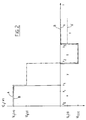
- FIG. 2 which represents a graph indicating, as a function of time, the potential difference U 1 (t) imposed between the current leads 8 and 9 during a complete coloring-discoloration cycle, will make it possible to explain the operation of the glazing units according to the invention (curves A, A ') relative to that of the glazing units described in European application EP-A-408 427 (curve B).
- phase x is the coloring phase
- phase y the maintenance phase in the colored state
- phase z the discoloration phase
- phase t the maintenance phase discolored state.
- a voltage U 1 (x) is maintained in level at a value of - 1.6 volts if the stack of example 1; at a value of around - 2 volts, if we use the stack of example 2, and at a value of around - 1.8 volts if we use the stack of example 3, these stacks then being devoid of the conductive seal 11 according to the invention.
- the colored tungsten oxide is then maintained in the y phase, phase during which, if it is prolonged for several days, the tungsten oxide tends to return to an almost discolored state by a phenomenon of parasitic self-discharge.
- a voltage U 1 of reverse polarity of + 0.6 volts is again imposed in level with the stack of example 1, of + 1 volt with the stack of example 2, + 0.8 volts with the stack of example 3, all free of the conductive joint 11.
- the voltage returns to zero, and the tungsten oxide remains in phase t discolored stable.
- curves A, A ′ where this time the stacks of examples 1 to 3 are used, provided with the conductive seal 11 according to FIG. 1, is different.
- a voltage U 1 (x) is imposed for the same period of time t o -t 1 , as before, so as not to exceed the limit of electrochemical stability of the electrochromic materials, at least at level of their peripheral zones which are instantly subjected to this value of U 1 without any ohmic loss. But as a corollary, the coloring at the edges of the glazing corresponding to its width will be slightly delayed compared to usual operation.
- phase y of coloring maintenance between the moments t 1 and t 2 , it is necessary this time, to maintain the degree of coloring indicated by the curve At 1 , impose a non-zero voltage U 1 (y) (FIG. 2) and preferably close to the thermodynamic equilibrium voltage of the oxidation-reduction couple in question, and in particular for the WO 3 / IrOy couple, of approximately - 1.2 V.
- the voltage U 1 (z) is equal to the voltage applied in normal operation, for the same reasons as in the coloring phase x.
- phase t of maintenance in the discolored state two possibilities are available: one can (curve A) impose a zero voltage, the discolored phase corresponding to the stable electrochemical state of the system, or (curve A ') impose a voltage non-zero, approximately 0.2 to 0.3 volts for example, continuously, so as to obtain a slightly greater discoloration.
- this graph represents a particular cycle, passing the material of a state completely discolored to a completely colored state
- the invention also applies without difficulty to the passage from one degree of coloring to another, by applying a lower voltage and / or for a shorter switching time.
- the invention is not limitative of switching phases x and z where the voltage U 1 varies in stages in "all or nothing".
- the difference lies in the fact that the electrical supply is adapted as a function of the discharge caused and controlled, and the choice of which depends on the requirements of the user.
- any slight contrast in coloring between the edges and the rest of the glazing can be perceived as annoying, as indifferent (in particular if the edges are hidden when the glazing is mounted on a building or a vehicle) or even as decorative.
- the invention could be applied to an electrochromic system whose state of electrochemical stability no longer corresponds to the discolored state, but to the colored state, the creation of the discharge thus allowing a return to the colored state in the event of an electrical failure.
- the electrochromic glazing according to the invention thus finds application both for equipping buildings by operating in transmission, and for equipping vehicles of the train, airplane type. In addition, it can function in reflection, in particular as a rear-view mirror.
Landscapes
- Physics & Mathematics (AREA)
- Nonlinear Science (AREA)
- Engineering & Computer Science (AREA)
- General Physics & Mathematics (AREA)
- Optics & Photonics (AREA)
- Chemical & Material Sciences (AREA)
- General Chemical & Material Sciences (AREA)
- Chemical Kinetics & Catalysis (AREA)
- Life Sciences & Earth Sciences (AREA)
- Geochemistry & Mineralogy (AREA)
- Materials Engineering (AREA)
- Organic Chemistry (AREA)
- Crystallography & Structural Chemistry (AREA)
- Multimedia (AREA)
- Mechanical Engineering (AREA)
- Electrochromic Elements, Electrophoresis, Or Variable Reflection Or Absorption Elements (AREA)
- Joining Of Glass To Other Materials (AREA)
Description
- L'invention concerne les vitrages à commande électrique du type électrochrome, c'est-à-dire les vitrages dont la coloration peut être modifiée sous l'effet d'un champ électrique.
- Leur principe de fonctionnement est basé sur l'utilisation d'une couche d'un matériau à propriété électrochrome, qui est capable d'insérer de manière réversible des cations, notamment des protons H+ ou des cations lithium Li+, et de ce fait passer d'un degré d'oxydation à un autre, sachant que chacun des degrés d'oxydation correspond à un état de coloration différent.
- Ainsi, le trioxyde de tungstène, pratiquement incolore dans son état oxydé (a), devient d'une coloration soutenue bleu-nuit dans son état réduit (b) en insérant des protons ou des cations Li+ selon la réaction suivante :

- Pour rendre possible ces changements de coloration réversibles, les vitrages électrochromes comportent deux substrats en verre entre lesquels on dispose deux couches électroconductrices transparentes munies d'amenées de courant, séparées successivement par une électrode constituée d'un matériau électrochrome dit cathodique tel que l'oxyde de tungstène, une contre-électrode, qui peut également être constituée d'un matériau électrochrome dit anodique comme l'oxyde d'iridium ou l'oxyde de nickel et une couche d'électrolyte qui permet le transfert des cations en question d'une électrode à l'autre.
- En utilisant en tant que contre-électrode de l'oxyde d'iridium, celui-ci, contrairement à l'électrode, est incolore à l'état réduit (b) où sont insérés des protons H+ et gris-jaune à l'état oxydé (a) où il est dépourvu de protons H+, ce qui renforce le contraste de coloration du vitrage, selon la réaction suivante :

- Une contre-électrode à base d'oxyde de nickel peut quant à elle, soit insérer des protons tout comme l'oxyde d'iridium, soit des cations lithium, comme il est connu de la demande de brevet EP-A-0 373 020 avec un schéma réactionnel plus complexe impliquant l'existence de plusieurs équilibres électrochromes.
- De manière schématique, en imposant une différence de potentiel, à la valeur et à la polarité voulues, aux deux couches électroconductrices, un transfert cationique s'effectue au travers de l'électrolyte d'une électrode à l'autre, engendrant une réaction d'insertion ou désinsertion desdits cations et donc une modification de l'aspect coloré global du vitrage. La mise au point d'un système d'alimentation électrique est donc cruciale pour le fonctionnement correct du vitrage. C'est ainsi que par exemple la demande de brevet européen EP-A-408 427 propose un système d'alimentation optimisant les temps de commutation du matériau électrochrome en disposant trois amenées de courant selon un montage type potentiostat et en imposant une différence de potentiel programmable et variable en fonction du temps. (On entend par temps de commutation le temps s'écoulant lors du passage d'un état de coloration donné à un autre état plus ou moins coloré que celui de départ). On peut ainsi compenser le phénomène de chutes ohmiques qui se produisent dans les couches électroconductrices, difficiles à éviter lorsqu'il s'agit de grands vitrages.
- Ce document procède donc à une modulation de la différence de potentiel imposée, qui permet de maîtriser le degré de coloration et le temps de commutation voulus.
- De tels vitrages sont particulièrement intéressants pour équiper bâtiments ou véhicules afin de contrôler l'apport solaire, et leurs applications envisagées tendent à se diversifier largement. Mais se pose alors un nouveau problème : le bon fonctionnement du vitrage électrochrome repose pour l'essentiel sur une alimentation électrique correcte et maîtrisée.
- En cas de dysfonctionnement du réseau électrique, par exemple en cas d'une déconnexion accidentelle d'une des amenées de courant ou même d'une fêlure du vitrage ou d'un décollement de sérigraphie, si le matériau électrochrome est alors relativement ou fortement coloré, l'opérateur n'a plus la possibilité de commander son retour à l'état pas ou peu coloré en un laps de temps rapide. Il ne peut qu'attendre un phénomène d'auto-décharge du système, phénomène heureusement à la cinétique extrêmement lente, d'au moins plusieurs jours, qui tend à faire retourner le matériau électrochrome de l'électrode dans son état d'auto-stabilité, qui correspond à son état quasiment complètement décoloré. Cette auto-décharge peut avoir différentes causes, plus ou moins élucidées et intrinsèques à la nature des couches utilisées dans l'empilement du système électrochrome : on peut vraisemblablement supposer que la couche d'électrolyte, qui est conductrice de cations, n'est pas un isolant électronique parfait par exemple. On peut aussi éventuellement penser à de faibles courts-circuits entre les couches électroconductrices.
- Or il peut se révéler important de pouvoir retourner très rapidement à l'état décoloré, ou pratiquement décoloré, en cas de défectuosité d'alimentation électrique. Ceci est d'autant plus vrai quand la sécurité peut être mise en jeu, lorsque l'on veut utiliser ces vitrages électrochromes pour équiper des véhicules, et notamment des cockpits d'avion ou des locomotives de trains, ou même lorsque ces vitrages équipent des rétroviseurs d'automobiles.
- C'est pourquoi le but de l'invention est de proposer des vitrages électrochromes qui, en cas de problème d'alimentation électrique, peuvent retourner à un état nettement décoloré dans un délai très court, par exemple d'au plus quelques minutes.
- Les auteurs de l'invention ont voulu détourner à leur profit le phénomène d'auto-décharge des vitrages électrochromes pour atteindre leur but. Ils ont volontairement créé un court-circuit permament entre les deux couches électroconductrices transparentes, de manière à créer une décharge du système électrochrome lorsque le matériau électrochrome cathodique est dans son état oxydé et coloré. Cette "décharge" provoquée volontairement est bien sûr beaucoup plus importante, et sans commune mesure avec le phénomène d'auto-décharge très lent souvent rencontré dans les systèmes électrochromes. Parallèlement, ils ont compensé ce transfert électronique tendant à supprimer la différence de potentiel imposée au système par une alimentation électrique adaptée.
- Ainsi, lorsque la couche de matériau électrochrome cathodique est colorée, s'il arrive que l'alimentation électrique soit défectueuse et qu'aux couches électroductrices plus aucune différence de potentiel ne puisse être appliquée, la décharge par court-circuit, qui n'est plus de ce fait compensée, conduit rapidement le matériau électrochrome vers son état de stabilité chimique, c'est-à-dire un état décoloré, à tout le moins très proche de son état décoloré maximal.
- Donc, deux points sont importants pour réaliser l'invention : d'une part, créer une décharge contrôlée, d'autre part, la compenser par une alimentation électrique adéquate.
- Le vitrage électrochrome selon l'invention comporte deux feuilles de verre revêtues chacune d'une couche électroconductrice transparente séparées l'une de l'autre successivement par une électrode en matériau électrochrome cathodique, un électrolyte et une contre-électrode. Ces couches électroconductrices sont reliées d'une part par au moins deux amenées de courant à un système d'alimentation électrique générant une différence de potentiel adaptée au changement de coloration voulu du matériau électrochrome. Ces couches électroconductrices munies d'amenées sont d'autre part reliées l'une à l'autre au niveau d'au moins une partie de leur périphérie par l'intermédiaire d'un matériau conducteur électronique dont la conductivité peut notamment être comprise entre 10-1 et 10+3ohm-1.cm-1, et de préférence d'environ 10+2ohm-1.cm-1.
- Au niveau de ce matériau conducteur transitent donc directement des électrons d'une couche électroconductrice à l'autre, transit que l'on maîtrise, puisque l'on choisit la conductivité du matériau, ses caractéristiques dimensionnelles, et, de par sa disposition, la manière dont il relie électriquement lesdites couches électroconductrices. On peut ainsi disposer ce matériau afin qu'il soit en contact, au moins en partie, avec au moins deux amenées de courant.
- On pourrait en fait le représenter sous la forme d'une différence de potentiel de polarité inverse de celle imposée aux couches électroconductrices lors de la commutation du matériau électrochrome vers un état plus coloré. On évalue et on contrôle ainsi précisément cette décharge.
- Un matériau conducteur électronique peut avantageusement être constitué d'une matrice polymérique au sein de laquelle sont noyées des particules conductrices. Cette matrice polymérique peut ainsi être à base de caoutchouc butyl et/ou polyisobutylène, de polysulfure ou de polyuréthane, tandis que l'on peut choisir les particules conductrices parmi des particules de graphite tel que le noir de carbone, le noir d'acétylène et/ou des particules métalliques. Généralement, le pourcentage volumique de ces particules conductrices par rapport à l'ensemble des particules et de la matrice polymérique est de préférence compris entre 10 et 20 %.
- On peut ainsi aisément sélectionner la conductivité électronique dudit matériau en dosant la quantité de particules par rapport à la quantité de polymère.
- On garde la maîtrise de la décharge également en choisissant la disposition de ce matériau conducteur vis-à-vis des couches électroconductrices et de leurs amenées de courant.
- En effet, si l'on utilise le montage potentiostat préconisé dans la demande de brevet européen EP-A-408 427 pré-citée, chacune desdites couches est munie d'une amenée de courant, les deux amenées diagonalement opposées étant disposées sur la longueur du vitrage électrochrome. Il peut exister également une amenée désignée comme point de référence, le potentiel électrique imposé entre les deux amenées permettant de s'assurer du potentiel souhaité entre l'une des amenées et le point de référence qui se trouve en vis-à-vis.
- Le mode de réalisation préféré de l'invention concerne un matériau à matière polymérique présent à la périphérie du vitrage et qui remplit simultanément la fonction de joint d'étanchéité à l'eau liquide et/ou vapeur ; joint qui, de toute manière, est indispensable pour protéger l'empilement des couches du vitrage électrochrome des aggressions extérieures. Le matériau peut alors contenir, outre les particules conductrices, du desséchant type tamis moléculaire. On simplifie ainsi le montage du vitrage. Mais ce matériau conducteur peut également être disposé sur le pourtour du vitrage uniquement en certains points répartis judicieusement.
- Dans un cas comme dans l'autre, il doit assurer une liaison électrique entre les deux couches électroconductrices, en évitant cependant de créer un court-circuit franc d'une couche à l'autre, ce qui endommagerait le système électrochrome. D'une manière générale, on contrôle le taux et la cinétique de la décharge par l'ajustement de la conductivité du matériau conducteur et par la longueur du "chemin électrique" que crée ce matériau d'une couche à l'autre.
- Pour compenser, au moins pour l'essentiel, cette décharge permanente par transfert électronique à travers ce matériau, lors du fonctionnement normal du vitrage, il faut adapter la différence de potentiel imposée aux couches électroconductrices, aussi bien lors d'une phase de coloration ou décoloration que lors du maintien à une coloration donnée du matériau électrochrome.
- C'est à la fois par le choix du matériau conducteur et de l'alimentation électrique que l'on peut alors selon l'invention opérer un compromis selon les applications envisagées.
- En effet, plus on souhaite un "temps de retour" rapide du vitrage électrochrome à son état décoloré en cas de problème d'alimentation électrique, et plus il faudra prévoir un matériau dont la conductivité élevée et la configuration propice engendreront une décharge importante. Cependant, on ne peut accentuer ce phénomène de décharge que jusqu'à une certaine limite, car il faut, dans chaque cas, adapter la puissance de l'alimentation électrique du vitrage dont le fonctionnement normal ne doit pas se trouver perturbé.
- Comme on l'explicitera ci-après, on ne peut pas toujours simplement se contenter d'appliquer une tension électrique supérieure qui compenserait en quelque sorte cette décharge : compte-tenu des surtensions aux interfaces, tout couple d'oxydo-réduction comme WO3/IrOy ou WO3/oxyde de nickel connaît des limites de stabilité électrochimique au-delà desquelles les matériaux risquent de se détériorer.
- En pratique, on impose usuellement des valeurs de tension "maximales" compte-tenu de ces limites intrinsèques au système électrochrome afin d'obtenir le contraste maximal entre l'état coloré et décoloré du vitrage. Aller au-delà avec un montage potentiostat risquerait de dégrader le dispositif, et pour commencer les zones périphériques des couches de matériaux électrochromes. Mais il ne faut cependant pas, par une alimentation électrique insuffisante, créer des inhomogénéités de coloration sur la surface du vitrage lorsqu'il est maintenu notamment en état coloré.
- Une fois "le temps de retour" déterminé par l'utilisateur, celui-ci devra donc choisir son alimentation électrique au mieux en fonction du paramètre qu'il considère le plus important (économie d'énergie électrique, homogénéité de surface parfaite ou non ...) et des matériaux électrochromes utilisés dans le vitrage.
- Avec le système selon l'invention, le "temps de retour" peut ainsi facilement être aussi court que le temps nécessaire au vitrage pour passer de l'état décoloré à l'état coloré sous l'effet de la différence de potentiel imposée à ses bornes.
- Pour donner un ordre de grandeur, ce système permet d'envisager un "temps de retour" à l'état décoloré de l'ordre de la minute pour un vitrage rectangulaire de dimensions 40 x 80 cm2, et de l'ordre d'au plus quelques dizaines de secondes pour un vitrage de 10 x 18 cm2, soit approximativement la taille d'un rétroviseur d'automobile.
- D'autres détails et caractéristiques avantageuses de l'invention ressortent de la description ci-après d'un mode de réalisation préféré, en référence aux dessins annexés qui représentent :
- en figure 1 : une coupe transversale simplifiée des vitrages électrochromes selon l'invention,
- en figure 2 : l'évolution en fonction du temps de la tension appliquée lors d'un cycle de coloration-décoloration à un vitrage électrochrome selon l'invention.
- La figure 1 représente une coupe transversale du vitrage électrochrome selon sa largeur, vitrage qui est muni soit d'un empilement de couches le faisant fonctionner par des réactions d'insertion/désinsertion de protons H+, soit d'un empilement de couches- le faisant fonctionner par des réactions d'insertion/désinsertion de cations Li+. Par souci de clarté, les rapports d'épaisseurs des différentes couches n'ont pas été respectés. En outre, n'est représenté le circuit d'alimentation électrique proprement dit que de manière extrêmement simplifiée, celui-ci pouvant être avantageusement celui de la demande de brevet européen précédemment mentionnée, selon un montage type potentiostat.
- Le vitrage est constitué de deux substrats de verre 1, 2, de deux couches électroconductrices transparentes 3, 4, d'une électrode en matériau électrochrome cathodique 5, d'une couche d'électrolyte 6 et d'une contre-électrode 7 en matériau électrochrome anodique. Deux amenées de courant 8 et 9 sont prévues pour alimenter les couches conductrices 3, 4. Ce sont des bandes métalliques diagonalement opposées et parallèles à la longueur du vitrage. La troisième amenée 10 est dite point de référence et se trouve en vis-à-vis de l'amenée 8. Le joint 11 sert à la fois de conducteur électronique d'une couche électroconductrice à l'autre et de joint d'étanchéité pour l'ensemble des couches.
- On impose entre les amenées de courant les plus proches (8, 9) une tension U1 correspondant à un potentiel U2 dit de consigne et mesuré entre l'amenée de courant 8 et le point de référence 10, conformément à la demande EP-A-408 427 à laquelle on se rapportera pour plus de détails.
- Dans le mode de réalisation préféré représenté à la figure 1, le joint 11, à la fois conducteur et garantissant l'étanchéité, est disposé de manière a être en contact avec les amenées 8 et 9. Cependant, on voit à la figure 1 que les couches électroconductrices 3, 4 sont disposées selon la longueur du vitrage de manière à ce que le joint conducteur 11 ait d'une part une large surface de contact avec l'une des couches électroconductrices et d'autre part une large surface de contact directe avec le substrat de verre opposé. (Il suffit d'utiliser, lors du dépôt des couches 3, 4, des "masques" pour obtenir cette configuration). On recommande également d'éviter que ce joint 11 ne recouvre simultanément l'amenée de courant 8 et le point de référence 10. Ainsi, on met au point un "chemin électrique" entre les couches électroconductrices 3, 4 sans pour autant provoquer de court-circuit direct intempestif entraînant la détérioration du système à la longue.
- A titre indicatif, on précise les caractéristiques de chacun des matériaux utilisés dans les différentes couches de trois empilements susceptibles d'être utilisés dans les vitrages de la figure 1.
- L'empilement suivant fonctionne par insertion/désinsertion de protons H+ au niveau de l'électrode 5 et de la contre-électrode 7, utilisant un électrolyte 6 solide conducteur de protons :
- substrats en verre 1,2 : feuilles de verre float de 1,5 mm d'épaisseur, de dimensions 10 x 18 cm2.
- couches électroconductrices 3,4 : oxyde d'indium dopé à l'étain, déposé par pulvérisation cathodique magnétron, d'épaisseur 400 nanomètres et de résistance carrée inférieure ou égale à 5 ohms,
- matériau électrochrome cathodique 5 : oxyde de tungstène WO3 déposé par pulvérisation cathodique magnétron réactive à partir d'une cible en tungstène en présence d'oxygène sous une pression de 20 millitorrs (soit 2,66 Pa).
- matériau électrochrome anodique 7 : oxyde d'iridium, déposé par pulvérisation cathodique assistée par champ magnétique, sous une pression de 6 millitorrs (soit 0,8 Pa) d'un mélange gazeux oxygène/hydrogène dans un rapport volumique 80/20, d'épaisseur 55 nanomètres,
- électrolyte 6 : solution solide d'acide phosphorique anhydre dans du polyoxyéthylène, d'épaisseur 50 micromètres, de conductivité à 20°C de 9.10-5 ohm-1.cm-1 et de transmission lumineuse supérieure à 85 %. Il est préparé de la manière suivante : dans des conditions anhydres, on dissout par litre de solvant de l'acide phosphorique anhydre (21,5 g) et du polyoxyéthylène de masse moléculaire 5 000 000 (densité 1,21 ; température de transition vitreuse -40°C ; rapport O/H du nombre d'atomes d'oxygène du polymère sur le nombre d'atomes d'hydrogène de l'acide égal à 0,66). Le solvant est un mélange 60/40 en volume d'acétonitrile et de tétrahydrofurane.
- La solution est coulée sous atmosphère à taux d'humidité contrôlé (inférieur ou égal à 50 ppm d'eau) par la méthode du tire-film sur le substrat recouvert de l'une ou l'autre des couches de matériau électrochrome. On évapore ensuite le solvant à température ambiante sous air sec pendant 20 h.
- L'empilement suivant fonctionne par insertion/désinsertion de cations Li+ dans l'électrode 5 et la contre-électrode 7, utilisant un électrolyte 6 solide conducteur de Li+ :
- Les substrats en verre 1, 2 les couches électroconductrices 3, 4 et l'électrode 5 sont identiques à ceux de l'exemple 1.
- matériau électrochrome anodique 7 : oxyde de nickel, déposé par pulvérisation cathodique assistée par champ magnétique en opérant sur une cible de nickel mince sous une tension de 250 V, avec un gaz plasmagène d'une pression de 3,33 Pa et un rapport oxygène/hydrogène de 80/20, selon l'enseignement de la demande EP-A-0 373 020. L'épaisseur de la couche 7 est d'environ 80 nm.
- électrolyte 6 : solution solide de perchlorate de lithium dans du polyoxyde d'éthylène, d'environ 50 micromètres d'épaisseur, selon la demande de brevet EP-A-0 013 199.
- Il est identique à l'exemple 2, seule est modifiée la nature de l'électrolyte 6, qui est sous forme de gel :
- électrolyte 6 : gel conducteur au lithium obtenu à partir d'un alcoxyde de titane selon la demande de brevet FR-A-2 593 321.
- Dans ces trois exemples et selon l'invention le joint 11 est en caoutchouc butyl et/ou polyisobutylène dans lequel sont dispersées des particules de noir de carbone. Sa conductivité électronique est comprise entre 1 et 103 ohm-1. cm-1, et ici de préférence d'environ 10+2 ohm-1. cm-1.
- Le pourcentage volumique des particules de noir de carbone par rapport à l'ensemble du polymère et des particules est compris entre 10 et 20 % et de préférence entre 14 et 18 %.
- L'assemblage des vitrages selon les exemples 1 à 3 est effectué par exemple selon l'enseignement de la demande de brevet français n° 90 11 419 déposée le 14 Septembre 1990 et correspondant à la demande européenne EP-A-477 065. Avant son fluage, ce joint se présente sous la forme d'un ruban de section rectangulaire 3 x 4 mm2. Il peut aussi être de section cylindrique.
- La figure 2, qui représente un graphe indiquant, en fonction du temps, la différence de potentiel U1(t) imposée entre les amenées de courant 8 et 9 lors d'un cycle complet de coloration-décoloration, va permettre d'expliciter le fonctionnement des vitrages selon l'invention (courbes A, A') par rapport à celui des vitrages décrits dans la demande européenne EP-A-408 427 (courbe B).
- Ce graphe distingue quatre phases x, y, z, t : la phase x est la phase de coloration, la phase y la phase de maintien en l'état coloré, la phase z la phase de décoloration et la phase t la phase de maintien de l'état décoloré.
- En fonctionnement connu, c'est-à-dire quand les vitrages ne sont pas munis du joint conducteur selon l'invention (courbe B), lors de la phase x de coloration, une tension U1(x) est maintenue en palier à une valeur de - 1,6 volts si on utilise l'empilement de l'exemple 1 ; à une valeur d'environ - 2 volts, si l'on utilise l'empilement de l'exemple 2, et à une valeur d'environ - 1,8 volt si l'on utilise l'empilement de l'exemple 3, ces empilements étant alors dépourvus du joint conducteur 11 selon l'invention. Puis, lorsque le degré de coloration voulu est obtenu, on cesse d'appliquer cette tension, on maintient alors l'oxyde de tungstène coloré en phase y, phase lors de laquelle, si elle se prolonge plusieurs jours, l'oxyde de tungstène tend à retourner à un état quasi décoloré par un phénomène d'auto-décharge parasitaire.
- En phase de décoloration z, on impose de nouveau une tension U1 de polarité inverse de + 0,6 volt en palier avec l'empilement de l'exemple 1, de + 1 volt avec l'empilement de l'exemple 2, de + 0,8 volt avec l'empilement de l'exemple 3, tous exempts du joint conducteur 11. Lorsque l'état décoloré voulu est obtenu, la tension revient à une valeur nulle, et l'oxyde de tungstène se maintient en phase t décolorée stable.
- Le fonctionnement selon l'invention (courbes A, A') où cette fois on utilise les empilements des exemples 1 à 3 munis du joint conducteur 11 selon la figure 1, est différent.
- En phase de coloration x, on impose une tension U1(x) pendant un même laps de temps to-t1, tout comme précédemment, de manière à ne pas dépasser la limite de stabilité électrochimique des matériaux électrochromes, tout au moins au niveau de leurs zones périphériques qui sont instantanément soumis à cette valeur de U1 sans aucune perte ohmique. Mais comme corollaire, la coloration au niveau des bords du vitrage correspondant à sa largeur accuseront un léger retard par rapport à un fonctionnement usuel.
- En fin de phase de coloration x, au temps t1, il peut persister une légère inhomogénéité de coloration entre les bords correspondant à la largeur et le reste du vitrage, inhomogénéité d'autant plus indiscernable que la conductivité du joint 11 n'est pas trop élevée. Dans la gamme de conductivité pré-citée, cette différence est à peine perceptible et n'entraîne aucun inconvénient notable.
- En phase y de maintien de coloration, entre les moments t1 et t2, il faut cette fois, pour maintenir le degré de coloration indiqué par la courbe At1, imposer une tension U1(y) non nulle (figure 2) et de préférence proche de la tension d'équilibre thermodynamique du couple d'oxydoréduction en question, et notamment pour le couple WO3/IrOy, d'environ - 1,2 V.
- En phase z de décoloration, la tension U1(z) est égale à la tension appliquée en fonctionnement habituel, pour les mêmes raisons que lors de la phase de coloration x.
- En phase t de maintien à l'état décoloré, deux possibilités s'offrent : on peut (courbe A) imposer une tension nulle, la phase décolorée correspondant à l'état électrochimique stable du système, ou (courbe A') imposer une tension non nulle, d'environ 0,2 à 0,3 volt par exemple, de manière continue, de manière à obtenir une décoloration légèrement plus importante.
- Avec ce système électrochrome, si une panne dans le réseau électrique se produit, le vitrage retourne à un état décoloré en moins de 15 secondes. Cet état décoloré est toutefois légèrement moins clair que l'état décoloré obtenu en imposant la tension U1(z) lors de la phase z du fonctionnement normal (figure 2, courbe B), car cet état d'auto-stabilité du couple oxydo-réducteur ne le conduit pas absolument entièrement à son état le plus transparent. Cependant, la visibilité est largement suffisante.
- Ainsi, lorsque le système se décharge par son joint conducteur en cas de défaut d'alimentation, il atteint une valeur de transmission lumineuse TL d'environ 55 %, alors que cette valeur est légèrement supérieure, d'environ 60 % lorsque sa décoloration s'effectue lors de son fonctionnement normal. (On rappelle que lorsque le matériau électrochrome est dans son état coloré, sa transmission lumineuse TL s'abaisse jusqu'à 10 %).
- Il est clair que si ce graphe représente un cycle particulier, faisant passer le matériau d'un état totalement décoloré à un état totalement coloré, l'invention s'applique également sans difficulté au passage d'un degré de coloration à un autre, en appliquant une tension plus faible et/ou pendant un temps de commutation plus court. De même, l'invention n'est pas limitative de phases de commutation x et z où la tension U1 varie par palier en "tout ou rien". La différence réside selon l'invention dans le fait que l'on adapte l'alimentation électrique en fonction de la décharge provoquée et maîtrisée, et dont le choix dépend des exigences de l'utilisateur. Ainsi, un éventuel léger contraste de coloration entre les bords et le reste du vitrage peut être perçu comme gênant, comme indifférent (notamment si les bords sont masqués lors du montage du vitrage sur un bâtiment ou un véhicule) ou même comme décoratif. On ajoute en outre que si dans le cas des empilements à transfert protonique, il n'est pas souhaitable dans le cadre de l'invention d'imposer des tensions U1(x) et U1(z) supérieures à celles imposées habituellement afin de ne pas risquer de détériorer les matériaux électrochromes à leur périphérie, en revanche dans le cas des empilements à transfert de cations lithium Li+, ce point est moins critique et il peut être envisagé d'imposer des valeurs légèrement supérieures (en valeurs absolues) de tensions U1(x) et U1(z).
- On pourrait en outre aisément envisager d'imposer une différence de potentiel qui tienne compte, outre de la décharge par court-circuit à travers le matériau conducteur électronique de l'invention, éventuellement aussi de l'auto-décharge intrinsèque aux systèmes électrochromes, qui, bien que d'ampleur bien moindre, pourraît être perçue comme gênante dans le cas où les vitrages sont destinés à rester colorés durant de très longues périodes.
- Grâce à l'invention, on remédie donc facilement à un inconvénient des systèmes électrochromes : le blocage du matériau électrochrome dans son état de coloration donné en cas de défaut d'alimentation électrique, et pour cela l'invention utilise avantageusement un phénomène de décharge, qui jusque là était considéré comme allant à l'encontre d'un fonctionnement satisfaisant d'un système électrochrome usuel.
- On pourrait, sans sortir du cadre de l'invention, appliquer l'invention à un système électrochrome dont l'état de stabilité électrochimique correspond non plus à l'état décoloré, mais à l'état coloré, la création de la décharge permettant ainsi un retour à l'état coloré en cas de panne électrique.
- Le vitrage électrochrome selon l'invention trouve ainsi application aussi bien pour équiper des bâtiments en fonctionnant en transmission, que pour équiper des véhicules type train, avion. En outre, il peut fonctionner en réflexion, notamment en tant que rétroviseur.
Claims (16)
- Vitrage électrochrome comportant deux feuilles de verre (1, 2) revêtues chacune d'une couche électroconductrice transparente (3, 4), séparées successivement par une électrode en matériau électrochrome (5), un électrolyte (6) et une contre-électrode (7), lesdites couches électroconductrices (3, 4) étant reliées par au moins deux amenées de courant (8, 9) à un système d'alimentation électrique générant une différence de potentiel (U1) en fonction de la modification de la coloration du matériau électrochrome voulue, caractérisé en ce que ces couches électroconductrices (3, 4) sont d'autre part reliées l'une à l'autre au niveau d'au moins une partie de leur périphérie par l'intermédiaire d'un matériau (11) conducteur électronique.
- Vitrage électrochrome selon la revendication 1, caractérisé en ce que son système d'alimentation électrique possède deux amenées de courant (8, 9) et un point de référence (10) selon un montage type potentiostat.
- Vitrage électrochrome selon la revendication 1 ou 2, caractérisé en ce que le matériau (11) conducteur électronique comporte une matrice polymérique dans laquelle sont noyées des particules conductrices électroniques.
- Vitrage électrochrome selon la revendication 3, caractérisé en ce que la matrice polymérique du matériau (11) conducteur électronique est à base de caoutchouc butyl et/ou polyisobutylène, de polysulfure ou de polyuréthane.
- Vitrage électrochrome selon la revendication 3 ou 4, caractérisé en ce que les particules conductrices du matériau (11) conducteur électronique sont à base de graphite comme du noir de carbone, du noir d'acétylène et/ou sont métalliques.
- Vitrage électrochrome selon l'une des revendications 3 à 5, caractérisé en ce que le pourcentage volumique des particules conductrices par rapport à l'ensemble desdites particules et de la matrice polymérique est compris entre 10 et 20 %.
- Vitrage électrochrome selon l'une des revendications précédentes, caractérisé en ce que le matériau (11) a une conductivité électronique comprise entre 10-1 et 10+3 ohm-1.cm-1 et de préférence d'environ 10+2 ohm-1.cm-1.
- Vitrage électrochrome selon l'une des revendications précédentes, caractérisé en ce que le matériau (11) conducteur électronique relie les deux couches électroconductrices (3, 4) sur la totalité de la périphérie du vitrage.
- Vitrage électrochrome selon l'une des revendications précédentes, caractérisé en ce que le matériau (11) conducteur électronique est en contact, au moins en partie, avec au moins les deux amenées de courant (8, 9).
- Vitrage électrochrome selon l'une des revendications 7 ou 8, caractérisé en ce que le matériau (11) conducteur électronique remplit également la fonction de joint d'étanchéité à l'eau liquide et/ou vapeur, de nature thermoplastique et contenant également de préférence un désséchant type tamis moléculaire.
- Vitrage électrochrome selon l'une des revendications précédentes, caractérisé en ce que la différence de potentiel U1 et la puissance d'alimentation imposées aux couches électroconductrices (3, 4) lors d'une phase de coloration ou décoloration de la couche (5) de matériau électrochrome ou lors du maintien à une coloration donnée de ladite couche (5), sont adaptées afin de tenir compte du transfert électronique d'une couche électroconductrice à l'autre par le matériau (11) à conducteur électronique.
- Vitrage électrochrome selon la revendication 10, caractérisé en ce qu'en cas de défaut d'alimentation électrique ou du réseau électrique, le matériau (11) présente la conductivité électronique suffisante pour que la liaison électrique qu'il assure entre les deux couches électroconductrices (3, 4) impose un retour de la couche (5) de matériau électrochrome à un état décoloré en un laps de temps approximativement égal au laps de temps nécessaire pour que la couche (5) de matériau électrochrome passe de l'état décoloré à l'état coloré sous l'effet d'une différence de potentiel, et est notamment de l'ordre d'une minute.
- Vitrage selon l'une des revendications 11 ou 12, caractérisé en ce que la différence de potentiel U1 imposée aux couches électroconductrices (3, 4) lors des phases de coloration (x) et décoloration (z) reste dans les limites de stabilité électrochimique de l'électrode (5) et de la contre-électrode (7), en ce que ladite différence de potentiel U1 imposée lors de la phase de maintien à l'état coloré (y) est proche de la valeur de la tension d'équilibre thermodynamique de l'électrode (5) et contre-électrode (7) et en ce que, lors de la phase de maintien à l'état décoloré (t), la différence de potentiel U1 est nulle ou non.
- Vitrage électrochrome selon l'une des revendications précédentes, caractérisé en ce qu'il fonctionne par réactions d'insertion/désinsertion de protons, notamment à l'aide d'une électrode (5) en oxyde de tungstène, d'une contre-électrode (7) en oxyde d'iridium et d'un électrolyte (6) conducteur de protons tel qu'une solution solide de polyoxyde d'éthylène et d'acide phosphorique.
- Vitrage électrochrome selon l'une des revendications 1 à 13, caractérisé en ce qu'il fonctionne par réactions d'insertion/désinsertion de cations lithium, notamment à l'aide d'une électrode (5) en oxyde de tungstène, une contre-électrode (7) à base d'oxyde de nickel et un électrolyte (6) conducteur de cations lithium soit composé d'une solution solide de perchlorate de lithium et de polyoxyde d'éthylène, soit composé d'un gel à partir d'un alcoxyde de titane.
- Application du vitrage électrochrome selon l'une des revendications précédentes à un vitrage fonctionnant en transmission pour le bâtiment, pour des véhicules tels que des trains, avions, ou à un vitrage fonctionnant en réflexion tel qu'un rétroviseur pour automobiles.
Priority Applications (6)
| Application Number | Priority Date | Filing Date | Title |
|---|---|---|---|
| FR929205246A FR2690536B1 (fr) | 1992-04-28 | 1992-04-28 | Vitrage electrochrome. |
| JP10112693A JP3308033B2 (ja) | 1992-04-28 | 1993-04-27 | エレクトロクロミック窓ガラス |
| US08/053,351 US5379146A (en) | 1992-04-28 | 1993-04-28 | Electrochromic pane |
| EP93401112A EP0622660B1 (fr) | 1992-04-28 | 1993-04-29 | Vitrage électrochrome |
| DK93401112.3T DK0622660T3 (da) | 1992-04-28 | 1993-04-29 | Elektrokrom rude |
| DE69314008T DE69314008T2 (de) | 1992-04-28 | 1993-04-29 | Elektrochrome Verglasung |
Applications Claiming Priority (2)
| Application Number | Priority Date | Filing Date | Title |
|---|---|---|---|
| FR929205246A FR2690536B1 (fr) | 1992-04-28 | 1992-04-28 | Vitrage electrochrome. |
| EP93401112A EP0622660B1 (fr) | 1992-04-28 | 1993-04-29 | Vitrage électrochrome |
Publications (2)
| Publication Number | Publication Date |
|---|---|
| EP0622660A1 EP0622660A1 (fr) | 1994-11-02 |
| EP0622660B1 true EP0622660B1 (fr) | 1997-09-17 |
Family
ID=26134681
Family Applications (1)
| Application Number | Title | Priority Date | Filing Date |
|---|---|---|---|
| EP93401112A Expired - Lifetime EP0622660B1 (fr) | 1992-04-28 | 1993-04-29 | Vitrage électrochrome |
Country Status (6)
| Country | Link |
|---|---|
| US (1) | US5379146A (fr) |
| EP (1) | EP0622660B1 (fr) |
| JP (1) | JP3308033B2 (fr) |
| DE (1) | DE69314008T2 (fr) |
| DK (1) | DK0622660T3 (fr) |
| FR (1) | FR2690536B1 (fr) |
Families Citing this family (180)
| Publication number | Priority date | Publication date | Assignee | Title |
|---|---|---|---|---|
| US5910854A (en) | 1993-02-26 | 1999-06-08 | Donnelly Corporation | Electrochromic polymeric solid films, manufacturing electrochromic devices using such solid films, and processes for making such solid films and devices |
| US5668663A (en) | 1994-05-05 | 1997-09-16 | Donnelly Corporation | Electrochromic mirrors and devices |
| US5780160A (en) * | 1994-10-26 | 1998-07-14 | Donnelly Corporation | Electrochromic devices with improved processability and methods of preparing the same |
| FR2751097B1 (fr) * | 1996-07-10 | 1998-09-11 | Saint Gobain Vitrage | Elements a proprietes optiques/energetiques variables |
| JP3904101B2 (ja) * | 1996-09-20 | 2007-04-11 | ソニー株式会社 | 光学装置及び電解液 |
| DE19723596C1 (de) * | 1997-06-05 | 1998-10-01 | Webasto Systemkomponenten Gmbh | Lichtdurchlässiger Deckel für ein Fahrzeugdach |
| US6172613B1 (en) | 1998-02-18 | 2001-01-09 | Donnelly Corporation | Rearview mirror assembly incorporating vehicle information display |
| US6124886A (en) | 1997-08-25 | 2000-09-26 | Donnelly Corporation | Modular rearview mirror assembly |
| US8294975B2 (en) | 1997-08-25 | 2012-10-23 | Donnelly Corporation | Automotive rearview mirror assembly |
| US6326613B1 (en) | 1998-01-07 | 2001-12-04 | Donnelly Corporation | Vehicle interior mirror assembly adapted for containing a rain sensor |
| DE19737978C2 (de) * | 1997-08-30 | 1999-09-16 | Bayer Ag | Elektrochromer Spiegel |
| US8288711B2 (en) | 1998-01-07 | 2012-10-16 | Donnelly Corporation | Interior rearview mirror system with forwardly-viewing camera and a control |
| US6445287B1 (en) | 2000-02-28 | 2002-09-03 | Donnelly Corporation | Tire inflation assistance monitoring system |
| US6477464B2 (en) | 2000-03-09 | 2002-11-05 | Donnelly Corporation | Complete mirror-based global-positioning system (GPS) navigation solution |
| US6553308B1 (en) | 1999-04-29 | 2003-04-22 | Donnelly Corporation | Vehicle-based navigation system with smart map filtering, portable unit home-base registration and multiple navigation system preferential use |
| US6329925B1 (en) * | 1999-11-24 | 2001-12-11 | Donnelly Corporation | Rearview mirror assembly with added feature modular display |
| US6693517B2 (en) | 2000-04-21 | 2004-02-17 | Donnelly Corporation | Vehicle mirror assembly communicating wirelessly with vehicle accessories and occupants |
| US7324261B2 (en) * | 1999-07-09 | 2008-01-29 | Gentex Corporation | Electrochromic devices with thin bezel-covered edge |
| US7064882B2 (en) * | 2002-09-30 | 2006-06-20 | Gentex Corporation | Electrochromic devices having no positional offset between substrates |
| US20020061718A1 (en) * | 1999-09-29 | 2002-05-23 | Treichel | Method and system for reducing photo-assisted corrosion in wafers during cleaning processes |
| AU2001243285A1 (en) | 2000-03-02 | 2001-09-12 | Donnelly Corporation | Video mirror systems incorporating an accessory module |
| US7370983B2 (en) | 2000-03-02 | 2008-05-13 | Donnelly Corporation | Interior mirror assembly with display |
| US7167796B2 (en) | 2000-03-09 | 2007-01-23 | Donnelly Corporation | Vehicle navigation system for use with a telematics system |
| WO2002062623A2 (fr) | 2001-01-23 | 2002-08-15 | Donnelly Corporation | Systeme d'eclairage ameliore destine a un vehicule |
| US7581859B2 (en) | 2005-09-14 | 2009-09-01 | Donnelly Corp. | Display device for exterior rearview mirror |
| KR100486786B1 (ko) * | 2002-02-27 | 2005-05-03 | 김태곤 | 다기능 복합 고무 전극 시트와 그의 응용 제품 |
| US6918674B2 (en) | 2002-05-03 | 2005-07-19 | Donnelly Corporation | Vehicle rearview mirror system |
| US7329013B2 (en) | 2002-06-06 | 2008-02-12 | Donnelly Corporation | Interior rearview mirror system with compass |
| AU2003237424A1 (en) * | 2002-06-06 | 2003-12-22 | Donnelly Corporation | Interior rearview mirror system with compass |
| US7360932B2 (en) * | 2004-06-01 | 2008-04-22 | Donnelly Corporation | Mirror assembly for vehicle |
| US7310177B2 (en) * | 2002-09-20 | 2007-12-18 | Donnelly Corporation | Electro-optic reflective element assembly |
| AU2003278863A1 (en) | 2002-09-20 | 2004-04-08 | Donnelly Corporation | Mirror reflective element assembly |
| WO2004103772A2 (fr) | 2003-05-19 | 2004-12-02 | Donnelly Corporation | Assemblage de retroviseur pour vehicule |
| US9134585B2 (en) | 2002-09-30 | 2015-09-15 | Gentex Corporation | Automotive rearview mirror with capacitive switches |
| US9346402B2 (en) | 2002-09-30 | 2016-05-24 | Gentex Corporation | Vehicular rearview mirror elements and assemblies incorporating these elements |
| US7372611B2 (en) * | 2002-09-30 | 2008-05-13 | Gentex Corporation | Vehicular rearview mirror elements and assemblies incorporating these elements |
| US7477439B2 (en) * | 2002-09-30 | 2009-01-13 | Gentex Corporation | Vehicular rear view mirror elements and assemblies incorporating these elements |
| US8004741B2 (en) | 2004-02-27 | 2011-08-23 | Gentex Corporation | Vehicular rearview mirror elements and assemblies incorporating these elements |
| US8169684B2 (en) | 2002-09-30 | 2012-05-01 | Gentex Corporation | Vehicular rearview mirror elements and assemblies incorporating these elements |
| ATE342824T1 (de) * | 2003-08-08 | 2006-11-15 | Brose Fahrzeugteile | Steuereinrichtung und verfahren zum ansteuern eines abblendbaren spiegels |
| US7446924B2 (en) | 2003-10-02 | 2008-11-04 | Donnelly Corporation | Mirror reflective element assembly including electronic component |
| US7308341B2 (en) | 2003-10-14 | 2007-12-11 | Donnelly Corporation | Vehicle communication system |
| KR100903415B1 (ko) | 2004-02-27 | 2009-06-18 | 젠텍스 코포레이션 | 차량의 후사경 요소들 및 이들 요소들을 포함하는 어셈블리 |
| US8064120B2 (en) * | 2004-03-12 | 2011-11-22 | The Boeing Company | Aircraft cabin services system including zone controllers for lighting control modules and dimmable windows |
| US7864398B2 (en) | 2004-06-08 | 2011-01-04 | Gentex Corporation | Electro-optical element including metallic films and methods for applying the same |
| US7372610B2 (en) | 2005-02-23 | 2008-05-13 | Sage Electrochromics, Inc. | Electrochromic devices and methods |
| ATE517368T1 (de) | 2005-05-16 | 2011-08-15 | Donnelly Corp | Fahrzeugspiegelanordnung mit zeichen am reflektierenden teil |
| CN101535087B (zh) | 2005-11-01 | 2013-05-15 | 唐纳利公司 | 具有显示装置的内部后视镜 |
| DE102006002948A1 (de) | 2006-01-21 | 2007-08-02 | Alexander Von Gencsy | Sichtsystem mit Stroboskopeffekt |
| US8169681B2 (en) | 2006-03-03 | 2012-05-01 | Gentex Corporation | Thin-film coatings, electro-optic elements and assemblies incorporating these elements |
| US8274729B2 (en) * | 2006-03-03 | 2012-09-25 | Gentex Corporation | Thin-film coatings, electro-optic elements and assemblies incorporating these elements |
| US8368992B2 (en) * | 2006-03-03 | 2013-02-05 | Gentex Corporation | Electro-optical element including IMI coatings |
| US7746534B2 (en) * | 2006-12-07 | 2010-06-29 | Gentex Corporation | Thin-film coatings, electro-optic elements and assemblies incorporating these elements |
| EP2426552A1 (fr) * | 2006-03-03 | 2012-03-07 | Gentex Corporation | Éléments électro-optiques incorporant des revêtements améliorés à couche mince |
| KR101275450B1 (ko) * | 2006-03-03 | 2013-06-17 | 젠텍스 코포레이션 | 개선된 박막 코팅, 전기 광학 요소 및 이들 요소를 포함하는 어셈블리 |
| US7688495B2 (en) * | 2006-03-03 | 2010-03-30 | Gentex Corporation | Thin-film coatings, electro-optic elements and assemblies incorporating these elements |
| CN101395521B (zh) * | 2006-03-03 | 2010-09-29 | 金泰克斯公司 | 改进的薄膜涂层、光电元件和包含这些元件的组件 |
| US7724415B2 (en) * | 2006-03-29 | 2010-05-25 | Casio Computer Co., Ltd. | Display drive device and display device |
| US10017847B2 (en) | 2007-03-05 | 2018-07-10 | Gentex Corporation | Method and apparatus for ion milling |
| US8649083B2 (en) | 2007-03-05 | 2014-02-11 | Gentex Corporation | Multi-zone mirrors |
| US8035881B2 (en) * | 2007-03-05 | 2011-10-11 | Gentex Corporation | Multi-zone mirrors |
| US9274394B2 (en) | 2007-03-05 | 2016-03-01 | Gentex Corporation | Multi-zone mirrors |
| EP2093270B1 (fr) | 2008-02-19 | 2017-11-01 | EControl-Glas GmbH & Co. KG | Utilisation d'antioxydants destinés à juguler un déchargement spontané |
| US8154418B2 (en) | 2008-03-31 | 2012-04-10 | Magna Mirrors Of America, Inc. | Interior rearview mirror system |
| US8514476B2 (en) | 2008-06-25 | 2013-08-20 | View, Inc. | Multi-pane dynamic window and method for making same |
| US7710671B1 (en) * | 2008-12-12 | 2010-05-04 | Applied Materials, Inc. | Laminated electrically tintable windows |
| EP2422227B1 (fr) | 2009-04-23 | 2014-05-14 | Magna Mirrors Of America, Inc. | Ensemble miroir pour véhicule |
| US11325533B2 (en) | 2009-04-23 | 2022-05-10 | Magna Mirrors Of America, Inc. | Frameless interior rearview mirror assembly |
| US9346403B2 (en) | 2009-10-07 | 2016-05-24 | Magna Mirrors Of America, Inc. | Rearview mirror assembly |
| US10261648B2 (en) | 2009-10-07 | 2019-04-16 | Magna Mirrors Of America, Inc. | Exterior rearview mirror assembly |
| CN102648113B (zh) | 2009-10-07 | 2015-05-27 | 麦格纳镜片美国有限公司 | 无框内部后视镜组件 |
| US11498486B2 (en) | 2009-10-07 | 2022-11-15 | Magna Mirrors Of America, Inc. | Vehicular exterior rearview mirror assembly |
| US11592723B2 (en) | 2009-12-22 | 2023-02-28 | View, Inc. | Automated commissioning of controllers in a window network |
| US11314139B2 (en) | 2009-12-22 | 2022-04-26 | View, Inc. | Self-contained EC IGU |
| US8213074B1 (en) | 2011-03-16 | 2012-07-03 | Soladigm, Inc. | Onboard controller for multistate windows |
| US10303035B2 (en) | 2009-12-22 | 2019-05-28 | View, Inc. | Self-contained EC IGU |
| US10690540B2 (en) | 2015-10-06 | 2020-06-23 | View, Inc. | Multi-sensor having a light diffusing element around a periphery of a ring of photosensors |
| US20130271813A1 (en) | 2012-04-17 | 2013-10-17 | View, Inc. | Controller for optically-switchable windows |
| US9056584B2 (en) | 2010-07-08 | 2015-06-16 | Gentex Corporation | Rearview assembly for a vehicle |
| US8270059B2 (en) | 2010-08-05 | 2012-09-18 | Soladigm, Inc. | Multi-pane electrochromic windows |
| US8164818B2 (en) | 2010-11-08 | 2012-04-24 | Soladigm, Inc. | Electrochromic window fabrication methods |
| US9958750B2 (en) | 2010-11-08 | 2018-05-01 | View, Inc. | Electrochromic window fabrication methods |
| US10180606B2 (en) | 2010-12-08 | 2019-01-15 | View, Inc. | Connectors for smart windows |
| CN112731720A (zh) | 2010-12-08 | 2021-04-30 | 唯景公司 | 绝缘玻璃装置的改良隔板 |
| US9442339B2 (en) | 2010-12-08 | 2016-09-13 | View, Inc. | Spacers and connectors for insulated glass units |
| US8643933B2 (en) | 2011-12-14 | 2014-02-04 | View, Inc. | Connectors for smart windows |
| US9454055B2 (en) | 2011-03-16 | 2016-09-27 | View, Inc. | Multipurpose controller for multistate windows |
| US10935865B2 (en) | 2011-03-16 | 2021-03-02 | View, Inc. | Driving thin film switchable optical devices |
| US9778532B2 (en) | 2011-03-16 | 2017-10-03 | View, Inc. | Controlling transitions in optically switchable devices |
| US8254013B2 (en) | 2011-03-16 | 2012-08-28 | Soladigm, Inc. | Controlling transitions in optically switchable devices |
| US9412290B2 (en) | 2013-06-28 | 2016-08-09 | View, Inc. | Controlling transitions in optically switchable devices |
| US10175549B2 (en) | 2011-03-16 | 2019-01-08 | View, Inc. | Connectors for smart windows |
| US10429712B2 (en) | 2012-04-20 | 2019-10-01 | View, Inc. | Angled bus bar |
| US11822202B2 (en) | 2011-03-16 | 2023-11-21 | View, Inc. | Controlling transitions in optically switchable devices |
| US8705162B2 (en) | 2012-04-17 | 2014-04-22 | View, Inc. | Controlling transitions in optically switchable devices |
| US9030725B2 (en) | 2012-04-17 | 2015-05-12 | View, Inc. | Driving thin film switchable optical devices |
| US9645465B2 (en) | 2011-03-16 | 2017-05-09 | View, Inc. | Controlling transitions in optically switchable devices |
| US11054792B2 (en) | 2012-04-13 | 2021-07-06 | View, Inc. | Monitoring sites containing switchable optical devices and controllers |
| US11630367B2 (en) | 2011-03-16 | 2023-04-18 | View, Inc. | Driving thin film switchable optical devices |
| CN103858242B (zh) * | 2011-08-26 | 2016-08-17 | 加州大学校务委员会 | 纳米结构的透明导电氧化物电致变色装置 |
| WO2013059674A1 (fr) | 2011-10-21 | 2013-04-25 | View, Inc. | Atténuation de choc thermique dans des fenêtres pouvant être colorées |
| US11048137B2 (en) | 2011-12-12 | 2021-06-29 | View, Inc. | Thin-film devices and fabrication |
| US10739658B2 (en) | 2011-12-12 | 2020-08-11 | View, Inc. | Electrochromic laminates |
| US12321075B2 (en) | 2011-12-12 | 2025-06-03 | View Operating Corporation | Electrochromic laminates |
| US10606142B2 (en) | 2011-12-12 | 2020-03-31 | View, Inc. | Thin-film devices and fabrication |
| US11719039B2 (en) | 2011-12-14 | 2023-08-08 | View, Inc. | Connectors for smart windows |
| US9316347B2 (en) | 2012-01-24 | 2016-04-19 | Gentex Corporation | Rearview assembly with interchangeable rearward viewing device |
| FR2986625B1 (fr) | 2012-02-06 | 2014-11-21 | Saint Gobain | Dispositif electrocommandable |
| US9341912B2 (en) | 2012-03-13 | 2016-05-17 | View, Inc. | Multi-zone EC windows |
| US12153320B2 (en) * | 2012-03-13 | 2024-11-26 | View, Inc. | Multi-zone EC windows |
| US11950340B2 (en) | 2012-03-13 | 2024-04-02 | View, Inc. | Adjusting interior lighting based on dynamic glass tinting |
| US11635666B2 (en) | 2012-03-13 | 2023-04-25 | View, Inc | Methods of controlling multi-zone tintable windows |
| US12578609B2 (en) | 2012-03-13 | 2026-03-17 | View Operating Corporation | Methods of controlling multi-zone tintable windows |
| RU2636811C2 (ru) | 2012-04-13 | 2017-12-01 | Вью, Инк. | Приложения для управления оптически переключаемыми устройствами |
| US11674843B2 (en) | 2015-10-06 | 2023-06-13 | View, Inc. | Infrared cloud detector systems and methods |
| US10048561B2 (en) | 2013-02-21 | 2018-08-14 | View, Inc. | Control method for tintable windows |
| US10503039B2 (en) | 2013-06-28 | 2019-12-10 | View, Inc. | Controlling transitions in optically switchable devices |
| US12400651B2 (en) | 2012-04-13 | 2025-08-26 | View Operating Corporation | Controlling optically-switchable devices |
| US10964320B2 (en) | 2012-04-13 | 2021-03-30 | View, Inc. | Controlling optically-switchable devices |
| US11300848B2 (en) | 2015-10-06 | 2022-04-12 | View, Inc. | Controllers for optically-switchable devices |
| US9638978B2 (en) | 2013-02-21 | 2017-05-02 | View, Inc. | Control method for tintable windows |
| US8879139B2 (en) | 2012-04-24 | 2014-11-04 | Gentex Corporation | Display mirror assembly |
| DK177557B1 (da) * | 2012-04-27 | 2013-10-14 | Sl Holding Kolding Aps | Intelligent temperaturstyret vindue |
| US11255120B2 (en) | 2012-05-25 | 2022-02-22 | View, Inc. | Tester and electrical connectors for insulated glass units |
| HK1212003A1 (en) | 2012-08-23 | 2016-06-03 | View, Inc. | Photonic-powered ec devices |
| WO2014032042A1 (fr) | 2012-08-24 | 2014-02-27 | Gentex Corporation | Ensemble de rétroviseur spécifiquement formé |
| US9327648B2 (en) | 2013-01-04 | 2016-05-03 | Gentex Corporation | Rearview assembly with exposed carrier plate |
| US9488892B2 (en) | 2013-01-09 | 2016-11-08 | Gentex Corporation | Printed appliqué and method thereof |
| US11719990B2 (en) | 2013-02-21 | 2023-08-08 | View, Inc. | Control method for tintable windows |
| US12372846B2 (en) | 2013-02-21 | 2025-07-29 | View Operating Corporation | Control methods and systems using external 3D modeling and schedule-based computing |
| US12422725B2 (en) | 2013-02-21 | 2025-09-23 | View Operating Corporation | Control methods and systems using outside temperature as a driver for changing window tint states |
| US11960190B2 (en) | 2013-02-21 | 2024-04-16 | View, Inc. | Control methods and systems using external 3D modeling and schedule-based computing |
| US11966142B2 (en) | 2013-02-21 | 2024-04-23 | View, Inc. | Control methods and systems using outside temperature as a driver for changing window tint states |
| WO2014134714A2 (fr) | 2013-03-07 | 2014-09-12 | Switch Materials Inc. | Joint d'étanchéité et système d'étanchéité pour dispositif en couches |
| CN103192768A (zh) * | 2013-03-29 | 2013-07-10 | 信利半导体有限公司 | 一种液晶防眩目后视镜 |
| US9174578B2 (en) | 2013-04-22 | 2015-11-03 | Magna Mirrors Of America, Inc. | Interior rearview mirror assembly |
| WO2014205014A1 (fr) | 2013-06-18 | 2014-12-24 | View, Inc. | Dispositifs électrochromiques sur des formes non rectangulaires |
| US9487142B2 (en) | 2013-06-25 | 2016-11-08 | Magna Mirrors Of America, Inc. | Rearview mirror assembly for vehicle |
| US9676336B2 (en) | 2013-06-25 | 2017-06-13 | Magna Mirrors Of America, Inc. | Exterior rearview mirror assembly for vehicle |
| US12061404B2 (en) | 2013-06-28 | 2024-08-13 | View, Inc. | Controlling transitions in optically switchable devices |
| US9885935B2 (en) | 2013-06-28 | 2018-02-06 | View, Inc. | Controlling transitions in optically switchable devices |
| US12353111B2 (en) | 2013-06-28 | 2025-07-08 | View Operating Corporation | Controlling transitions in optically switchable devices |
| US9575315B2 (en) | 2013-09-24 | 2017-02-21 | Gentex Corporation | Display mirror assembly |
| US9454054B2 (en) | 2013-11-18 | 2016-09-27 | Magna Mirrors Of America, Inc. | Electro-optic mirror element and process of making same |
| WO2015089663A1 (fr) | 2013-12-19 | 2015-06-25 | Switch Materials Inc. | Objets commutables et procédés de fabrication |
| US10221612B2 (en) | 2014-02-04 | 2019-03-05 | View, Inc. | Infill electrochromic windows |
| US10859983B2 (en) | 2014-03-05 | 2020-12-08 | View, Inc. | Monitoring sites containing switchable optical devices and controllers |
| CN104073812B (zh) * | 2014-07-16 | 2016-09-28 | 武汉大学 | 一种发电机紫铜导线在除盐水中的防腐蚀方法 |
| DE102014012736A1 (de) | 2014-08-26 | 2016-03-03 | Gt Elektrotechnische Produkte Gmbh | Polymermaterialien auf der Basis von Polyurethanen, Epoxidharzen, polymeren Siloxanen oder Siliconen oder thermoplastischen Polymeren, Verfahren zu ihrer Herstellung und ihre Verwendung |
| WO2016044746A1 (fr) | 2014-09-19 | 2016-03-24 | Gentex Corporation | Ensemble rétroviseur |
| WO2016073848A1 (fr) | 2014-11-07 | 2016-05-12 | Gentex Corporation | Actionneur de miroir d'affichage plein écran |
| US10071689B2 (en) | 2014-11-13 | 2018-09-11 | Gentex Corporation | Rearview mirror system with a display |
| CN107107825B (zh) | 2014-12-03 | 2020-08-21 | 金泰克斯公司 | 用于车辆的显示镜组件 |
| USD746744S1 (en) | 2014-12-05 | 2016-01-05 | Gentex Corporation | Rearview device |
| WO2016100075A1 (fr) | 2014-12-15 | 2016-06-23 | View, Inc. | Joints pour fenêtres électrochromiques |
| JP2018513810A (ja) | 2015-04-20 | 2018-05-31 | ジェンテックス コーポレイション | 装飾を備えた後方視認アセンブリ |
| EP3297870B1 (fr) | 2015-05-18 | 2020-02-05 | Gentex Corporation | Dispositif de rétroviseur plein affichage |
| TWI823168B (zh) | 2015-07-07 | 2023-11-21 | 美商唯景公司 | 用於可著色窗戶之控制方法 |
| CN108136962B (zh) | 2015-09-30 | 2021-06-29 | 金泰克斯公司 | 全显示镜 |
| US11255722B2 (en) | 2015-10-06 | 2022-02-22 | View, Inc. | Infrared cloud detector systems and methods |
| CA3003639A1 (fr) | 2015-10-29 | 2017-05-04 | View, Inc. | Dispositifs de commande pour dispositifs a commutation optique |
| WO2017075473A1 (fr) | 2015-10-30 | 2017-05-04 | Gentex Corporation | Rétroviseur |
| WO2017075420A1 (fr) | 2015-10-30 | 2017-05-04 | Gentex Corporation | Manette à bascule |
| USD845851S1 (en) | 2016-03-31 | 2019-04-16 | Gentex Corporation | Rearview device |
| USD817238S1 (en) | 2016-04-29 | 2018-05-08 | Gentex Corporation | Rearview device |
| EP3449300B1 (fr) | 2016-04-29 | 2022-09-07 | View, Inc. | Étalonnage de paramètres électriques dans des fenêtres à commutation optique |
| US10025138B2 (en) | 2016-06-06 | 2018-07-17 | Gentex Corporation | Illuminating display with light gathering structure |
| USD809984S1 (en) | 2016-12-07 | 2018-02-13 | Gentex Corporation | Rearview assembly |
| USD854473S1 (en) | 2016-12-16 | 2019-07-23 | Gentex Corporation | Rearview assembly |
| US11320713B2 (en) | 2017-02-16 | 2022-05-03 | View, Inc. | Solar power dynamic glass for heating and cooling buildings |
| EP3369754A1 (fr) | 2017-03-03 | 2018-09-05 | EControl-Glas GmbH & Co. KG | Composition destinée à fabriquer un polymère, procédé de fabrication du polymère, ledit polymère, utilisation du polymère et vitrage à gradation électrique comprenant le polymère |
| US11454854B2 (en) | 2017-04-26 | 2022-09-27 | View, Inc. | Displays for tintable windows |
| DE202018000981U1 (de) | 2018-02-23 | 2018-04-26 | Adrien Jathe | Richtungsabhängige Verdunklungstechnik um eine blitzartige automatische helligkeitsgesteuerte progressive sektorale stufenlose Lichtreduzierung zu bewirken (unter sektoral wird die Einteilung des Blickfeldes in viele kleine Sektoren verstanden); anwendbar für Brillen, (Helm-)Visiere und optische Geräte |
| WO2020018493A1 (fr) * | 2018-07-18 | 2020-01-23 | Gentex Corporation | Dispositif électro-optique avec fil intégré dans un joint adhésif |
| US11631493B2 (en) | 2020-05-27 | 2023-04-18 | View Operating Corporation | Systems and methods for managing building wellness |
| CN110471230B (zh) * | 2019-09-06 | 2021-10-08 | 南通繁华新材料科技有限公司 | 一种电致变色玻璃及其制造方法 |
| TW202206925A (zh) | 2020-03-26 | 2022-02-16 | 美商視野公司 | 多用戶端網路中之存取及傳訊 |
| CN112147828B (zh) * | 2020-09-04 | 2023-06-30 | Oppo广东移动通信有限公司 | 电子设备、壳体组件、盖板组件以及电致变色模组 |
| KR102397829B1 (ko) * | 2020-12-18 | 2022-05-12 | 에스케이씨 주식회사 | 전기 변색소자의 구동제어 방법 및 장치 |
| US20230229051A1 (en) * | 2022-01-18 | 2023-07-20 | Furcifer Inc. | Method and device for controlling states of dynamic glass |
Family Cites Families (11)
| Publication number | Priority date | Publication date | Assignee | Title |
|---|---|---|---|---|
| JPS59184328A (ja) * | 1983-04-04 | 1984-10-19 | Nissan Motor Co Ltd | 透過度可変ガラス |
| JPS6111727A (ja) * | 1984-06-28 | 1986-01-20 | Nissan Motor Co Ltd | 透過型エレクトロクロミツク素子 |
| JPS63298224A (ja) * | 1987-05-28 | 1988-12-06 | Toyobo Co Ltd | エレクトロクロミック機能を有する合わせガラス |
| JP2503553B2 (ja) * | 1987-11-30 | 1996-06-05 | 凸版印刷株式会社 | エレクトロクロミック表示体 |
| FR2639441A1 (fr) * | 1988-11-21 | 1990-05-25 | Saint Gobain Vitrage | Contre-electrode pour systemes electrochromes |
| JP3041822B2 (ja) * | 1989-07-11 | 2000-05-15 | サン―ゴバン ヒトラージュ アンテルナショナル | エレクトロクロミック装置および使用方法 |
| FR2649691B1 (fr) * | 1989-07-11 | 1992-10-30 | Saint Gobain Vitrage Int | Vitrage electrochrome |
| JPH0483234A (ja) * | 1990-07-26 | 1992-03-17 | Osaka Gas Co Ltd | エレクトロクロミック表示素子の運転方法 |
| FR2666804B1 (fr) * | 1990-09-14 | 1993-05-28 | Saint Gobain Vitrage Int | Vitrage electrochrome. |
| FR2666805B1 (fr) * | 1990-09-14 | 1992-10-30 | Saint Gobain Vitrage Int | Procede d'obtention de vitrages electrochromes. vitrages electrochromes. |
| JP3854378B2 (ja) * | 1997-07-24 | 2006-12-06 | 株式会社フォルザ・オペレーションシステムズ | 陶土圧延装置 |
-
1992
- 1992-04-28 FR FR929205246A patent/FR2690536B1/fr not_active Expired - Fee Related
-
1993
- 1993-04-27 JP JP10112693A patent/JP3308033B2/ja not_active Expired - Fee Related
- 1993-04-28 US US08/053,351 patent/US5379146A/en not_active Expired - Lifetime
- 1993-04-29 EP EP93401112A patent/EP0622660B1/fr not_active Expired - Lifetime
- 1993-04-29 DE DE69314008T patent/DE69314008T2/de not_active Expired - Fee Related
- 1993-04-29 DK DK93401112.3T patent/DK0622660T3/da active
Also Published As
| Publication number | Publication date |
|---|---|
| FR2690536B1 (fr) | 1994-06-17 |
| EP0622660A1 (fr) | 1994-11-02 |
| JPH0692695A (ja) | 1994-04-05 |
| DE69314008T2 (de) | 1998-04-16 |
| DK0622660T3 (da) | 1998-05-11 |
| US5379146A (en) | 1995-01-03 |
| JP3308033B2 (ja) | 2002-07-29 |
| DE69314008D1 (de) | 1997-10-23 |
| FR2690536A1 (fr) | 1993-10-29 |
Similar Documents
| Publication | Publication Date | Title |
|---|---|---|
| EP0622660B1 (fr) | Vitrage électrochrome | |
| EP0408427B1 (fr) | Vitrage électrochrome | |
| EP0628849B1 (fr) | Vitrage électrochrome | |
| EP0683419B1 (fr) | Procédé d'alimentation d'un système électrochrome | |
| EP0867752B1 (fr) | Dispositif électrochimique | |
| EP0718667B1 (fr) | Procédé d'alimentation électrique de deux vitrages électrochromes | |
| EP1451634B1 (fr) | Electrode de dispositifs electrochimiques et/ou electrocommandables | |
| CN102388341B (zh) | 低缺陷率电致变色装置的制造 | |
| EP0831360B1 (fr) | Dispositif électrochimique | |
| EP0486387B1 (fr) | Vitrage électrochrome | |
| EP2010384A1 (fr) | Vitrage feuilleté et ses moyens d'étanchéification et de renforcement périphérique | |
| EP1012662A1 (fr) | Procede de traitement d'un dispositif electrochimique | |
| FR2886419A1 (fr) | Electrode de dispositifs electrochimiques/ electrocommandables | |
| EP0373020B1 (fr) | Contre-électrode pour systèmes électrochromes | |
| CA1321256C (fr) | Vitrage a transmission variable du type electrochrome | |
| FR2669122A1 (fr) | Vitrage electrochrome. | |
| FR2633609A1 (fr) | Systeme electrochrome | |
| WO2010004158A1 (fr) | Electrode isolante pour dispositif électrochimique | |
| FR2908228A1 (fr) | Couche transparente a haute conductivite electrique avec grille metallique a tenue electrochimique optimisee | |
| EP0770900A1 (fr) | Vitrage électrochrome |
Legal Events
| Date | Code | Title | Description |
|---|---|---|---|
| PUAI | Public reference made under article 153(3) epc to a published international application that has entered the european phase |
Free format text: ORIGINAL CODE: 0009012 |
|
| AK | Designated contracting states |
Kind code of ref document: A1 Designated state(s): BE CH DE DK FR GB IT LI LU SE |
|
| 17P | Request for examination filed |
Effective date: 19950128 |
|
| GRAG | Despatch of communication of intention to grant |
Free format text: ORIGINAL CODE: EPIDOS AGRA |
|
| 17Q | First examination report despatched |
Effective date: 19961121 |
|
| GRAH | Despatch of communication of intention to grant a patent |
Free format text: ORIGINAL CODE: EPIDOS IGRA |
|
| RAP1 | Party data changed (applicant data changed or rights of an application transferred) |
Owner name: SAINT-GOBAIN VITRAGE |
|
| GRAH | Despatch of communication of intention to grant a patent |
Free format text: ORIGINAL CODE: EPIDOS IGRA |
|
| GRAA | (expected) grant |
Free format text: ORIGINAL CODE: 0009210 |
|
| AK | Designated contracting states |
Kind code of ref document: B1 Designated state(s): BE CH DE DK FR GB IT LI LU SE |
|
| REG | Reference to a national code |
Ref country code: CH Ref legal event code: EP |
|
| REF | Corresponds to: |
Ref document number: 69314008 Country of ref document: DE Date of ref document: 19971023 |
|
| ITF | It: translation for a ep patent filed | ||
| REG | Reference to a national code |
Ref country code: CH Ref legal event code: NV Representative=s name: KIRKER & CIE SA |
|
| GBT | Gb: translation of ep patent filed (gb section 77(6)(a)/1977) |
Effective date: 19971211 |
|
| REG | Reference to a national code |
Ref country code: DK Ref legal event code: T3 |
|
| PLBE | No opposition filed within time limit |
Free format text: ORIGINAL CODE: 0009261 |
|
| STAA | Information on the status of an ep patent application or granted ep patent |
Free format text: STATUS: NO OPPOSITION FILED WITHIN TIME LIMIT |
|
| 26N | No opposition filed | ||
| REG | Reference to a national code |
Ref country code: GB Ref legal event code: IF02 |
|
| PGFP | Annual fee paid to national office [announced via postgrant information from national office to epo] |
Ref country code: DK Payment date: 20080430 Year of fee payment: 16 Ref country code: DE Payment date: 20080508 Year of fee payment: 16 Ref country code: CH Payment date: 20080502 Year of fee payment: 16 |
|
| PGFP | Annual fee paid to national office [announced via postgrant information from national office to epo] |
Ref country code: IT Payment date: 20080429 Year of fee payment: 16 |
|
| PGFP | Annual fee paid to national office [announced via postgrant information from national office to epo] |
Ref country code: SE Payment date: 20080408 Year of fee payment: 16 |
|
| PGFP | Annual fee paid to national office [announced via postgrant information from national office to epo] |
Ref country code: GB Payment date: 20080430 Year of fee payment: 16 |
|
| PGFP | Annual fee paid to national office [announced via postgrant information from national office to epo] |
Ref country code: LU Payment date: 20090415 Year of fee payment: 17 Ref country code: FR Payment date: 20090416 Year of fee payment: 17 |
|
| PGFP | Annual fee paid to national office [announced via postgrant information from national office to epo] |
Ref country code: BE Payment date: 20090519 Year of fee payment: 17 |
|
| REG | Reference to a national code |
Ref country code: CH Ref legal event code: PL |
|
| REG | Reference to a national code |
Ref country code: DK Ref legal event code: EBP |
|
| EUG | Se: european patent has lapsed | ||
| GBPC | Gb: european patent ceased through non-payment of renewal fee |
Effective date: 20090429 |
|
| PG25 | Lapsed in a contracting state [announced via postgrant information from national office to epo] |
Ref country code: LI Free format text: LAPSE BECAUSE OF NON-PAYMENT OF DUE FEES Effective date: 20090430 Ref country code: DE Free format text: LAPSE BECAUSE OF NON-PAYMENT OF DUE FEES Effective date: 20091103 Ref country code: CH Free format text: LAPSE BECAUSE OF NON-PAYMENT OF DUE FEES Effective date: 20090430 |
|
| PG25 | Lapsed in a contracting state [announced via postgrant information from national office to epo] |
Ref country code: GB Free format text: LAPSE BECAUSE OF NON-PAYMENT OF DUE FEES Effective date: 20090429 Ref country code: DK Free format text: LAPSE BECAUSE OF NON-PAYMENT OF DUE FEES Effective date: 20090430 |
|
| BERE | Be: lapsed |
Owner name: *SAINT-GOBAIN VITRAGE Effective date: 20100430 |
|
| REG | Reference to a national code |
Ref country code: FR Ref legal event code: ST Effective date: 20101230 |
|
| PG25 | Lapsed in a contracting state [announced via postgrant information from national office to epo] |
Ref country code: IT Free format text: LAPSE BECAUSE OF NON-PAYMENT OF DUE FEES Effective date: 20090429 Ref country code: BE Free format text: LAPSE BECAUSE OF NON-PAYMENT OF DUE FEES Effective date: 20100430 |
|
| PG25 | Lapsed in a contracting state [announced via postgrant information from national office to epo] |
Ref country code: SE Free format text: LAPSE BECAUSE OF NON-PAYMENT OF DUE FEES Effective date: 20090430 |
|
| PG25 | Lapsed in a contracting state [announced via postgrant information from national office to epo] |
Ref country code: FR Free format text: LAPSE BECAUSE OF NON-PAYMENT OF DUE FEES Effective date: 20100430 |
|
| PG25 | Lapsed in a contracting state [announced via postgrant information from national office to epo] |
Ref country code: LU Free format text: LAPSE BECAUSE OF NON-PAYMENT OF DUE FEES Effective date: 20100429 |