EP0622766A1 - Gitterantenne für elektronisches Gegenstand-Überwachungssystem - Google Patents
Gitterantenne für elektronisches Gegenstand-Überwachungssystem Download PDFInfo
- Publication number
- EP0622766A1 EP0622766A1 EP94106468A EP94106468A EP0622766A1 EP 0622766 A1 EP0622766 A1 EP 0622766A1 EP 94106468 A EP94106468 A EP 94106468A EP 94106468 A EP94106468 A EP 94106468A EP 0622766 A1 EP0622766 A1 EP 0622766A1
- Authority
- EP
- European Patent Office
- Prior art keywords
- coil
- field
- producing
- sections
- segment
- Prior art date
- Legal status (The legal status is an assumption and is not a legal conclusion. Google has not performed a legal analysis and makes no representation as to the accuracy of the status listed.)
- Granted
Links
Images


Classifications
-
- G—PHYSICS
- G08—SIGNALLING
- G08B—SIGNALLING SYSTEMS, e.g. PERSONAL CALLING SYSTEMS; ORDER TELEGRAPHS; ALARM SYSTEMS
- G08B13/00—Burglar, theft or intruder alarms
- G08B13/22—Electrical actuation
- G08B13/24—Electrical actuation by interference with electromagnetic field distribution
- G08B13/2402—Electronic Article Surveillance [EAS], i.e. systems using tags for detecting removal of a tagged item from a secure area, e.g. tags for detecting shoplifting
- G08B13/2465—Aspects related to the EAS system, e.g. system components other than tags
- G08B13/2468—Antenna in system and the related signal processing
- G08B13/2474—Antenna or antenna activator geometry, arrangement or layout
-
- H—ELECTRICITY
- H01—ELECTRIC ELEMENTS
- H01Q—ANTENNAS, i.e. RADIO AERIALS
- H01Q7/00—Loop antennas with a substantially uniform current distribution around the loop and having a directional radiation pattern in a plane perpendicular to the plane of the loop
- H01Q7/04—Screened antennas
Definitions
- This invention relates to electronic article surveillance systems and, in particular, to coil/lattice configurations for producing and detecting magnetic fields in intertogation zones associated with such systems.
- EAS electronic article surveillance
- the '697 patent proposes the use of a pair of lattice assemblies positioned parallel with each other, on opposite sides of an interrogation zone extending therebetween.
- a rhomboid-shaped transmitting, i.e., field-producing, coil is to be positioned within each of the lattices, with the diagonal side of each coil being oppositely directed; e.g., the coil on one side of the zone has its diagonal side directed upward, while the diagonal side of the other coil is directed downward with respect to a desired passageway through the zone.
- a lazy-8 receiver coil also be positioned parallel with and alongside each transmitting coil.
- one embodiment depicted in the '198 patent proposes the use of a pair of transmitting coils in one lattice assembly on one side of the zone, and a pair of receiving coils in another lattice assembly positioned parallel with the first lattice, but located on the other side of the zone.
- the transmitting coils are in substantially the same plane, are offset both horizontally and vertically, and are connected so that current flows in the same direction in both coils.
- That embodiment also requires the use of similarly offset DC energized bias coils. While the vertical and horizontal offset facilitates the production of differently directed field components throughout the zone, it requires the use of dual, different lattice assemblies.
- the '877 patent depicts another variant.
- a pair of field coils and a pair of receiving coils are all enclosed in a single lattice.
- the field-producing coils are basically rectangular, with smaller rectangular coils being centered within a larger, more square one.
- the coils are connected so that current flows in the same direction in both.
- the lattices are used in pairs on opposite sides of the interrogation zone, and are connected so that current in the coils on one side flows in the opposite direction from that in the coils on the other side, when all are viewed from the same side of the zone.
- a lattice assembly bearing some similarity to that adapted to enclose the coil assembly of the present invention is also set forth in U.S. Patent No. 4,994,939, however, the coil assembly contained within the lattice assembly is not configured to provide extended, multidirectional detection throughout an interrogation zone.
- the coil assembly of the present invention differs significantly from those described above, and includes features resulting in field distributions in an associated interrogation zone which still further enhance the detectability of EAS magnetic markers therein regardless of orientation.
- the assembly of the present invention thus also includes a field-producing coil which includes at least a pair of substantially similarly configured coil segments juxtaposed in substantially a coplanar orientation.
- each segment has a pair of spaced apart and mutually parallel vertical arms, a top, substantially horizontal section connecting the upper ends of the vertical arms, and a bottom, at least partially diagonal section connecting the lower end of the vertical arms.
- each segment is spaced apart a like distance such that the segments are substantially juxtaposed.
- the respective bottom sections of each segment are located at substantially the same level, each having at least a part thereof positioned at an opposite diagonal angle with respect to a similarly positioned part of the bottom section of the other segment.
- the segments are connected such that current applied thereto is additive in the top sections so as to produce an intensified magnetic field in the upper half of the coil assembly to enhance the detectability of EAS markers positioned proximate thereto.
- the field resulting from current in the diagonally positioned bottom sections at least partially cancels and, thus, minimizes interference from electromagnetically active objects proximate a surface on which the said associated EAS system may be positioned.
- top sections of each segment are located at a different, predetermined height, thus producing a vertically extended magnetic field to improve the detection of markers located in upper regions of the zone.
- the field-producing coil includes at least a pair of substantially similarly configured trapezoidal coil segments positioned alongside each other in substantially a coplanar orientation, each trapezoidal segment having
- the pair of coil Segments is positioned so that the longer arm of one segment is alongside the shorter arm of the other segment, the lower end of each longer arm is positioned at substantially the same level, and the top horizontal sections are, therefore, positioned at different levels.
- the coil assembly also includes a detector coil positioned adjacent to and substantially coplanar with the field-producing coil, the detector coil having two sections connected in a lazy Figure-8 configuration.
- each half of the bottom section of the detector coil extends diagonally so as to be adjacent a respective diagonally configured bottom section of the field-producing coil, and the top section of the detector coil extends appreciably above the topmost horizontal section of the field-producing coil so as to detect fringe fields resulting from the field-producing coil.
- FIG. 1 shows an installation of the coil assembly of the preSent invention as would typically be enclosed within a coil lattice and positioned adjacent an exit 12 from a secured facility such as a retail store, library or the like.
- a secured facility such as a retail store, library or the like.
- FIG. 1 shows an installation of the coil assembly of the preSent invention as would typically be enclosed within a coil lattice and positioned adjacent an exit 12 from a secured facility such as a retail store, library or the like.
- a second lattice 10A which is positioned parallel to and spaced apart from the first so as to define an interrogation zone 11 therebetween.
- a customer, patron, etc., 14 may be detected as that person passes through the interrogation zone carrying an object 16 to which a marker 18 is attached.
- each coil assembly 20 includes a field-producing coil 22 and a detector coil 24.
- the marker 18 will interact with fields produced by the field-producing coils within the lattices 10 and 10A, such as the coil 22, when those coils are energized by the AC field power supply 26. This, in turn, will cause the respective detector coils, such as detector coil 24, to respond such that a signal is detected by the signal detector and alarm indicator circuits 28. This, in turn, will create a suitable alarm such as may be provided by a flashing light 30 or buzzer 31 mounted on top of one or the other of the lattices.
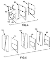
- Figure 2 shows a front view of half of a lattice 34 within which is positioned a coil assembly 36 comprising a field-producing coil 37.
- the coil 37 includes two substantially similarly-shaped trapezoidal coil Segments 38 and 40.
- the Segments are juxtaposed in substantially a coplanar orientation, one of the coils being positioned as a mirror image of the other.
- the segment 40 is also constructed to be shorter than is the segment 38, both segments then being positioned so that the opposite longer legs 42 and 44 of each segment are equidistant from the bottom 46 of the lattice, the top horizontal sections 48 and 50 thereby being at different, predetermined heights.
- each segment 38 and 40 respectively, includes two turns, with the second turn of one segment being connected to the first turn of the other segment so that the two segments 38 and 40 are connected in series.
- the arrows adjacent the respective legs and sections of each segment thus show that current flows in the same direction in both top sections 48 and 50.
- the resultant magnetic fields reinforce each other and intensify the fields in the upper regions of the zone, enhancing the detectability of markers there positioned.
- the field coil used in this invention was configured using two trapezoidal coils with the horizontal top elements spaced 356 mm apart, with the overlapped portions of the vertical arms being 356 mm high, and vertical height of the diagonal section being 356 mm.
- the width of the coil was 712 mm, and was configured using six turns of six gauge litz wire.
- Figure 3 further shows a front view of a lattice 54 within which is positioned a coil assembly 56 comprising a detector coil 58. While separately shown in Figure 3 for purposes of clarity, it will be understood, as shown in Figure 1, that a preferred coil assembly will include a detector coil positioned adjacent to and substantially coplanar with the field-producing coil.
- the detector coil 58 has two sections 60 and 62, which are connected in a lazy Figure-8 configuration.
- the coil thus, comprises spaced-apart vertical arms 64 and 66 terminating at respective upper and lower ends at substantially the same respective levels, two center vertical arms 68 and 70 that cross over each other, and top and bottom sections 72 and 74, respectively, connecting each of the spaced-apart arms 64 and 66 to one of the center arms 68 and 70 so that the left half of the top section 72 is connected to the right half of the bottom section 74 and vice versa.
- Each half of the bottom section of the detector coil thus extends diagonally so as to be adjacent a respective diagonally- configured bottom section of the field-producing coil.
- the top section 72 of the detector coil extends appreciably above the topmost horizontal section of the field-producing coil so as to readily detect markers positioned in that region and which are now accessed as a result of the increased intensity field resulting from the reinforced currents flowing in both the top sections of the field-producing coil.
- the detector coil was configured as described above using one turn of 18-gauge, six-conductor instrumentation wire, in which the respective conductors were connected in series so as to create six turns.
- the chosen dimensions was such that the width of the coil was 715 mm, with the bottom section shaped to mirror the diagonal bottom section of the field-producing coil and the top sections extending 381 mm above the top of the topmost horizontal section of the field coil, while conforming to the top section of the lattice.
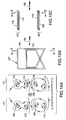
- each of the coils comprises two Segments 84 and 86.
- Each segment has a trapezoidal shape and is positioned in a mirror image to the opposite segment.
- each segment 84 and 86 includes a top section 88 and 90 which are parallel to each other and are positioned at different heights so as to extend the field in an upper part of the resultant interrogation zone.
- Each coil further includes opposing vertical arms 92 and 94, and 96 and 98, and oppositely diagonally directed bottom legs 100 and 102.
- the two segments in each of the coils are preferably connected in series, and further connected so that current in the respective coils is oppositely directed in the center coil.
- the field-producing coils 78, 80 and 82 are further shown in Figure 5, with detector coils 104, 106, and 108 respectively positioned adjacent one of the field-producing coils.
- the detector coils, each having the "lazy-8" configuration set forth in Figure 3, are, in turn, connected to maximize detection in an interrogation zone having an extended width and height.
- Figures 6 through 12 set forth various alternative configurations of the field-producing coils of the present invention.
- the coil 110 may include two segments of substantially the same size, juxtaposed and positioned in a mirror image so that the diagonal legs are oppositely directed.
- the respective top sections 112 and 114 will also be juxtaposed, rather than spaced apart as in the coils previously described.
- the field-producing coil 112 may be constructed so that the respective bottom sections 118 and 120 rather than being straight, diagonally-positioned sections, are each angled so that a portion is downwardly directed, while another portion is upwardly directed.
- the segments further have the respective downward and upward directed portions of both sections extending along a common line.
- the coil may have other than straight top sections.
- Figures 8 and 9 show embodiments in which the coils 122 ( Figure 8) and 124 ( Figure 9) have one or both of the top sections 126, 128 and 130 curved, as might be desired to correspond with the overall shape of a detection coil included in the assembly.
- Figures 10 and 11 represent embodiments in which the coils 132 and 134 have segments in which one or more of the respective top sections 136, 138, 140 and 142 are straight, with oppositely angled portions.
- the coil 144 may have segments in which the juxtaposed arms 146 and 148, and 150 and 152, while being substantially vertical, diverge or converge. Other variants are likewise within the scope of the invention.
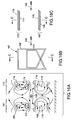
- Figure 13 represents a pair of spaced-apart, field-producing coil assemblies of the prior art, with Figure 13A showing a cross section of an interrogation zone, 13B showing a side view, and 13C showing a top view.
- Figure 13B thus shows but one of the coil assemblies 154, the other being positioned directly behind it.
- the assembly 156 includes two substantially square sections 156 and 158 positioned so that the respective vertical arms are aligned, and with the horizontal sections offset so that the bottom horizontal section of the top section 156 intersects the mid-point of the lower section 158. (Such a configuration is set forth in U.S. Patent No.
- FIG. 13A A plane proximate to the entrance, represented in those views as E-E, is shown in Figure 13A together with representative field distribution lines.
- E-E A plane proximate to the entrance, represented in those views as E-E, is shown in Figure 13A together with representative field distribution lines.
- the field patterns generated by such a coil and current configuration is such that the vertical field component is symmetric with respect to the top and bottom horizontal coil elements, with that in the bottom elements being in opposing direction.
- the cancellation of the bottom vertical field with the top vertical field occurs at the geometric center of the combined assembly.
- the bottom vertical field below the coil is the same as that extending above the top pair of coils.
- the field density occurring at the plane E-E, and likewise at a similarly positioned plane at the exit from the zone is essentially the minimum vertical pattern existing anywhere in the zone.
- Figures 14A-C represent substantially the same coil and current configuration as that discussed in conjunction with Figures 13A-C, but differ in that the view shown in Figure 14A is taken along a plane C-C, proximate a distance halfway along the corridor.
- the vertical field component is still symmetric with respect to the top and bottom horizontal coil sections.
- the cancellation of the bottom vertical field with the top vertical field again occurs at the geometric center horizontal plane of the assembly.
- interference from electromagnetically active objects, such as reinforcing rods below the floor, etc. may occur.
- the vertical field density occurring at the plane C-C in the corridor is the maximum occurring anywhere along the corridor.
- Figures 15 and 16 represent front, top and side views of coil assemblies according to the present invention, and, in particular, correspond to the single corridor, trapezoidal assemblies shown in Figure 1.
- one assembly 167 includes Segments 168 and 170
- the other assembly 172 includes segments 174 and 176.
- the field patterns are such that the cancellation of the vertical field components in the lower portion of the zone are minimized due to the smaller vertical field resulting from the opposing diagonal elements.
- the vertical field adjacent to the upper horizontal elements is slightly increased over that shown in Figure 13A.
- marker detection is still further enhanced thereover by the use of extended height detector coils, as shown in Figure 3 in both the left and right coil assemblies.
- the lower vertical area is also smaller and thereby creates a smaller external field, thus lessening adverse effects from external sources such as those as may be located below the floor.
- the vertical field density occurring at the plane C-C is the maximum occurring anywhere along the corridor. Overall, coverage in the upper vertical field is maximized, and the external field in the lower half is minimized, thus lessening external interference.
Landscapes
- Engineering & Computer Science (AREA)
- Physics & Mathematics (AREA)
- Signal Processing (AREA)
- Automation & Control Theory (AREA)
- Computer Security & Cryptography (AREA)
- Electromagnetism (AREA)
- General Physics & Mathematics (AREA)
- Burglar Alarm Systems (AREA)
- Geophysics And Detection Of Objects (AREA)
- Support Of Aerials (AREA)
Applications Claiming Priority (2)
| Application Number | Priority Date | Filing Date | Title |
|---|---|---|---|
| US08/055,689 US5440296A (en) | 1993-04-29 | 1993-04-29 | Coil assembly for electronic article surveillance system |
| US55689 | 1993-04-29 |
Publications (2)
| Publication Number | Publication Date |
|---|---|
| EP0622766A1 true EP0622766A1 (de) | 1994-11-02 |
| EP0622766B1 EP0622766B1 (de) | 1998-11-25 |
Family
ID=21999538
Family Applications (1)
| Application Number | Title | Priority Date | Filing Date |
|---|---|---|---|
| EP94106468A Expired - Lifetime EP0622766B1 (de) | 1993-04-29 | 1994-04-26 | Gitterantenne für elektronisches Gegenstand-Überwachungssystem |
Country Status (5)
| Country | Link |
|---|---|
| US (1) | US5440296A (de) |
| EP (1) | EP0622766B1 (de) |
| JP (1) | JP3565897B2 (de) |
| CA (1) | CA2120183C (de) |
| DE (1) | DE69414751T2 (de) |
Cited By (4)
| Publication number | Priority date | Publication date | Assignee | Title |
|---|---|---|---|---|
| WO1995028748A1 (en) * | 1994-04-18 | 1995-10-26 | Finlayson, Dorothy, Elizabeth | Antenna arrangement |
| AU672556B2 (en) * | 1994-04-18 | 1996-10-03 | Delaval Holding Ab | Antenna arrangement |
| FR2806213A1 (fr) * | 2000-03-07 | 2001-09-14 | Valeo Electronique | Antenne, systeme de communication de vehicule et vehicule equipes d'une telle antenne |
| EP1328912A4 (de) * | 2000-10-10 | 2005-05-11 | Escort Memory Systems | Modulares rfid-antennensystem |
Families Citing this family (23)
| Publication number | Priority date | Publication date | Assignee | Title |
|---|---|---|---|---|
| EP0829108B1 (de) * | 1995-05-30 | 2007-03-28 | Sensormatic Electronics Corporation | Antennenanordnung für warenüberwachungssystem mit verbesserter abfragefeldverteilung |
| USD421402S (en) * | 1997-09-05 | 2000-03-07 | Checkpoint Systems, Inc. | Antenna for an alarm system |
| US6094137A (en) * | 1998-04-22 | 2000-07-25 | Rasch; Arnan R. | Book binding, machine, and method for incorporating electronic article surveillance marker into a book |
| US6061552A (en) * | 1998-04-28 | 2000-05-09 | Sensormatic Electronics Corporation | EAS pedestal and method for making the same |
| JP3996293B2 (ja) * | 1999-03-01 | 2007-10-24 | 高千穂交易株式会社 | 物品監視装置及び物品監視システム |
| ITAR20000040A1 (it) * | 2000-09-08 | 2002-03-08 | Alessandro Manneschi | Trasduttore lettore di transponder per il controllo dei passaggi |
| JP3498716B2 (ja) * | 2001-02-09 | 2004-02-16 | オムロン株式会社 | アンテナ装置 |
| WO2002091615A1 (en) * | 2001-05-04 | 2002-11-14 | Koninklijke Philips Electronics N.V. | Communication device with a coil configuration for the communication with stationary data carriers |
| US6836216B2 (en) * | 2002-05-09 | 2004-12-28 | Electronic Article Surveillance Technologies, Ltd. | Electronic article surveillance system |
| JP3964782B2 (ja) * | 2002-12-26 | 2007-08-22 | 株式会社日立国際電気 | タグ情報管理装置、タグ情報管理用アンテナ |
| US8072330B1 (en) | 2004-04-14 | 2011-12-06 | Smartguard, Llc | Hard cover product with concealed printed security device |
| US7233246B2 (en) * | 2004-04-14 | 2007-06-19 | Smartguard, Llc | Hard cover product with spine-disposed concealed security device |
| US7411499B2 (en) * | 2004-04-14 | 2008-08-12 | Smartguard, Llc | Hard cover product with concealed security device |
| US7557717B2 (en) * | 2004-04-14 | 2009-07-07 | Smartguard, Llc | Hard cover product with concealed security device |
| US7183918B1 (en) * | 2004-04-14 | 2007-02-27 | Smartguard, Llc | Intermediate cover board with concealed security device for hard cover product |
| JP2009094865A (ja) * | 2007-10-10 | 2009-04-30 | Univ Of Electro-Communications | テレビジョンおよび液晶テレビジョン |
| EP2232636B1 (de) * | 2007-11-28 | 2018-08-22 | Qualcomm Incorporated | Erhöhung der drahtlosreichweite anhand der verwendung parasitärer antennen |
| US20110148636A1 (en) * | 2009-12-17 | 2011-06-23 | 3M Innovative Properties Company | Detection system |
| US9424724B2 (en) | 2013-08-02 | 2016-08-23 | Bibliotheca Rfid Library Systems Ag | Single turn magnetic drive loop for electronic article surveillance |
| WO2015028343A1 (en) * | 2013-08-30 | 2015-03-05 | Koninklijke Philips N.V. | Coil arrangement of a mpi system or apparatus |
| GB2617357B (en) * | 2022-04-05 | 2024-09-11 | Endomagnetics Ltd | Improvements in or relating to susceptibility probes for detecting surgical markers |
| CN119001870A (zh) * | 2023-12-15 | 2024-11-22 | 深圳市安卫普科技有限公司 | 通过式探测设备及其线圈装置和线圈调零方法 |
| CN222734287U (zh) * | 2023-12-15 | 2025-04-08 | 深圳市安卫普科技有限公司 | 一种线圈结构及通过式探测器 |
Citations (5)
| Publication number | Priority date | Publication date | Assignee | Title |
|---|---|---|---|---|
| US4135183A (en) * | 1977-05-24 | 1979-01-16 | Minnesota Mining And Manufacturing Company | Antipilferage system utilizing "figure-8" shaped field producing and detector coils |
| US4309697A (en) * | 1980-10-02 | 1982-01-05 | Sensormatic Electronics Corporation | Magnetic surveillance system with odd-even harmonic and phase discrimination |
| GB2133660A (en) * | 1982-11-09 | 1984-07-25 | Tag Radionics Ltd | Transponder detection systems |
| EP0130286A2 (de) * | 1983-06-30 | 1985-01-09 | Knogo Corporation | Verfahren und Einrichtung zum Erkennen von Markierungselementen in einer Überwachungszone |
| US4994939A (en) * | 1989-11-15 | 1991-02-19 | Minnesota Mining And Manufacturing Company | Universal lattice for magnetic-electronic article surveillance system |
Family Cites Families (5)
| Publication number | Priority date | Publication date | Assignee | Title |
|---|---|---|---|---|
| US3665449A (en) * | 1969-07-11 | 1972-05-23 | Minnesota Mining & Mfg | Method and apparatus for detecting at a distance the status and identity of objects |
| US3697996A (en) * | 1969-07-11 | 1972-10-10 | Minnesota Mining & Mfg | Electromagnetic field producing apparatus and method for sequentially producing a plurality of fields |
| US4326198A (en) * | 1976-08-18 | 1982-04-20 | Knogo Corporation | Method and apparatus for the promotion of selected harmonic response signals in an article detection system |
| US4135184A (en) * | 1977-08-31 | 1979-01-16 | Knogo Corporation | Electronic theft detection system for monitoring wide passageways |
| US4274090A (en) * | 1980-02-19 | 1981-06-16 | Knogo Corporation | Detection of articles in adjacent passageways |
-
1993
- 1993-04-29 US US08/055,689 patent/US5440296A/en not_active Expired - Lifetime
-
1994
- 1994-03-29 CA CA002120183A patent/CA2120183C/en not_active Expired - Fee Related
- 1994-04-22 JP JP8442094A patent/JP3565897B2/ja not_active Expired - Fee Related
- 1994-04-26 DE DE69414751T patent/DE69414751T2/de not_active Expired - Lifetime
- 1994-04-26 EP EP94106468A patent/EP0622766B1/de not_active Expired - Lifetime
Patent Citations (5)
| Publication number | Priority date | Publication date | Assignee | Title |
|---|---|---|---|---|
| US4135183A (en) * | 1977-05-24 | 1979-01-16 | Minnesota Mining And Manufacturing Company | Antipilferage system utilizing "figure-8" shaped field producing and detector coils |
| US4309697A (en) * | 1980-10-02 | 1982-01-05 | Sensormatic Electronics Corporation | Magnetic surveillance system with odd-even harmonic and phase discrimination |
| GB2133660A (en) * | 1982-11-09 | 1984-07-25 | Tag Radionics Ltd | Transponder detection systems |
| EP0130286A2 (de) * | 1983-06-30 | 1985-01-09 | Knogo Corporation | Verfahren und Einrichtung zum Erkennen von Markierungselementen in einer Überwachungszone |
| US4994939A (en) * | 1989-11-15 | 1991-02-19 | Minnesota Mining And Manufacturing Company | Universal lattice for magnetic-electronic article surveillance system |
Cited By (5)
| Publication number | Priority date | Publication date | Assignee | Title |
|---|---|---|---|---|
| WO1995028748A1 (en) * | 1994-04-18 | 1995-10-26 | Finlayson, Dorothy, Elizabeth | Antenna arrangement |
| AU672556B2 (en) * | 1994-04-18 | 1996-10-03 | Delaval Holding Ab | Antenna arrangement |
| US6043792A (en) * | 1994-04-18 | 2000-03-28 | Alfa Laval Agri Ab | Single antenna arrangement providing interrogation field |
| FR2806213A1 (fr) * | 2000-03-07 | 2001-09-14 | Valeo Electronique | Antenne, systeme de communication de vehicule et vehicule equipes d'une telle antenne |
| EP1328912A4 (de) * | 2000-10-10 | 2005-05-11 | Escort Memory Systems | Modulares rfid-antennensystem |
Also Published As
| Publication number | Publication date |
|---|---|
| CA2120183C (en) | 2002-02-26 |
| DE69414751D1 (de) | 1999-01-07 |
| DE69414751T2 (de) | 1999-07-29 |
| JPH06334418A (ja) | 1994-12-02 |
| JP3565897B2 (ja) | 2004-09-15 |
| US5440296A (en) | 1995-08-08 |
| CA2120183A1 (en) | 1994-10-30 |
| EP0622766B1 (de) | 1998-11-25 |
Similar Documents
| Publication | Publication Date | Title |
|---|---|---|
| US5440296A (en) | Coil assembly for electronic article surveillance system | |
| US4135183A (en) | Antipilferage system utilizing "figure-8" shaped field producing and detector coils | |
| EP0829108B1 (de) | Antennenanordnung für warenüberwachungssystem mit verbesserter abfragefeldverteilung | |
| JPH06342065A (ja) | 電子式物品監視システム及び方法 | |
| US4751516A (en) | Antenna system for magnetic and resonant circuit detection | |
| CA2251326C (en) | Electronic article surveillance system | |
| JPS5922997B2 (ja) | 電子窃盗検出システム | |
| US6362739B1 (en) | Passive security device for detecting ferromagnetic objects | |
| EP0440370B1 (de) | Verbundantenne für ein elektronisches Ueberwachungssystem zur Verhinderung von Warendiebstahl | |
| US5406262A (en) | Adjusting magnetic bias field intensity in EAS presence detection system to enhance detection | |
| EP0472013B1 (de) | Elektronische Warenüberwachungsanlage und Antennenstruktur dafür | |
| US4866455A (en) | Antenna system for magnetic and resonant circuit detection | |
| CA2258772A1 (en) | Magnetic reading devices | |
| CA1295030C (en) | Antipilferage systems | |
| US20030001739A1 (en) | Electronic article surveillance antenna for attachment to a vertical structure | |
| EP0428384A2 (de) | Universales Gitter für eine magnetisch elektronische Warenüberwachungsanlage | |
| EP0238458B1 (de) | Anwesenheitsdetektionsempfangsvorrichtung | |
| AU695927B2 (en) | Device for detecting an article provided with an electronic security tag | |
| KR820000703B1 (ko) | 8자형 자장 형성 코일 및 검파 코일을 이용한 도난방지 시스템 | |
| EP0130973A1 (de) | Anti-ladendiebstahlsystem | |
| JPS60168294A (ja) | 防犯装置 |
Legal Events
| Date | Code | Title | Description |
|---|---|---|---|
| PUAI | Public reference made under article 153(3) epc to a published international application that has entered the european phase |
Free format text: ORIGINAL CODE: 0009012 |
|
| AK | Designated contracting states |
Kind code of ref document: A1 Designated state(s): DE FR GB IT NL SE |
|
| 17P | Request for examination filed |
Effective date: 19950425 |
|
| 17Q | First examination report despatched |
Effective date: 19970822 |
|
| GRAG | Despatch of communication of intention to grant |
Free format text: ORIGINAL CODE: EPIDOS AGRA |
|
| GRAG | Despatch of communication of intention to grant |
Free format text: ORIGINAL CODE: EPIDOS AGRA |
|
| GRAH | Despatch of communication of intention to grant a patent |
Free format text: ORIGINAL CODE: EPIDOS IGRA |
|
| GRAH | Despatch of communication of intention to grant a patent |
Free format text: ORIGINAL CODE: EPIDOS IGRA |
|
| GRAA | (expected) grant |
Free format text: ORIGINAL CODE: 0009210 |
|
| AK | Designated contracting states |
Kind code of ref document: B1 Designated state(s): DE FR GB IT NL SE |
|
| PG25 | Lapsed in a contracting state [announced via postgrant information from national office to epo] |
Ref country code: IT Free format text: LAPSE BECAUSE OF FAILURE TO SUBMIT A TRANSLATION OF THE DESCRIPTION OR TO PAY THE FEE WITHIN THE PRE;WARNING: LAPSES OF ITALIAN PATENTS WITH EFFECTIVE DATE BEFORE 2007 MAY HAVE OCCURRED AT ANY TIME BEFORE 2007. THE CORRECT EFFECTIVE DATE MAY BE DIFFERENT FROM THE ONE RECORDED.SCRIBED TIME-LIMIT Effective date: 19981125 |
|
| REF | Corresponds to: |
Ref document number: 69414751 Country of ref document: DE Date of ref document: 19990107 |
|
| ET | Fr: translation filed | ||
| PLBE | No opposition filed within time limit |
Free format text: ORIGINAL CODE: 0009261 |
|
| STAA | Information on the status of an ep patent application or granted ep patent |
Free format text: STATUS: NO OPPOSITION FILED WITHIN TIME LIMIT |
|
| 26N | No opposition filed | ||
| REG | Reference to a national code |
Ref country code: GB Ref legal event code: IF02 |
|
| PGFP | Annual fee paid to national office [announced via postgrant information from national office to epo] |
Ref country code: NL Payment date: 20020329 Year of fee payment: 9 |
|
| PG25 | Lapsed in a contracting state [announced via postgrant information from national office to epo] |
Ref country code: NL Free format text: LAPSE BECAUSE OF NON-PAYMENT OF DUE FEES Effective date: 20031101 |
|
| NLV4 | Nl: lapsed or anulled due to non-payment of the annual fee |
Effective date: 20031101 |
|
| PGFP | Annual fee paid to national office [announced via postgrant information from national office to epo] |
Ref country code: SE Payment date: 20100428 Year of fee payment: 17 |
|
| PGFP | Annual fee paid to national office [announced via postgrant information from national office to epo] |
Ref country code: DE Payment date: 20110420 Year of fee payment: 18 Ref country code: FR Payment date: 20110426 Year of fee payment: 18 |
|
| PGFP | Annual fee paid to national office [announced via postgrant information from national office to epo] |
Ref country code: GB Payment date: 20110420 Year of fee payment: 18 |
|
| REG | Reference to a national code |
Ref country code: SE Ref legal event code: EUG |
|
| GBPC | Gb: european patent ceased through non-payment of renewal fee |
Effective date: 20120426 |
|
| REG | Reference to a national code |
Ref country code: FR Ref legal event code: ST Effective date: 20121228 |
|
| PG25 | Lapsed in a contracting state [announced via postgrant information from national office to epo] |
Ref country code: GB Free format text: LAPSE BECAUSE OF NON-PAYMENT OF DUE FEES Effective date: 20120426 |
|
| REG | Reference to a national code |
Ref country code: DE Ref legal event code: R119 Ref document number: 69414751 Country of ref document: DE Effective date: 20121101 |
|
| PG25 | Lapsed in a contracting state [announced via postgrant information from national office to epo] |
Ref country code: FR Free format text: LAPSE BECAUSE OF NON-PAYMENT OF DUE FEES Effective date: 20120430 |
|
| PG25 | Lapsed in a contracting state [announced via postgrant information from national office to epo] |
Ref country code: SE Free format text: LAPSE BECAUSE OF NON-PAYMENT OF DUE FEES Effective date: 20110427 |
|
| PG25 | Lapsed in a contracting state [announced via postgrant information from national office to epo] |
Ref country code: DE Free format text: LAPSE BECAUSE OF NON-PAYMENT OF DUE FEES Effective date: 20121101 |