EP0622768B1 - Elektrische Schweissmaschine mit einer Fernsteuerung - Google Patents
Elektrische Schweissmaschine mit einer Fernsteuerung Download PDFInfo
- Publication number
- EP0622768B1 EP0622768B1 EP94105826A EP94105826A EP0622768B1 EP 0622768 B1 EP0622768 B1 EP 0622768B1 EP 94105826 A EP94105826 A EP 94105826A EP 94105826 A EP94105826 A EP 94105826A EP 0622768 B1 EP0622768 B1 EP 0622768B1
- Authority
- EP
- European Patent Office
- Prior art keywords
- switching
- current
- implement
- unit
- assigned
- Prior art date
- Legal status (The legal status is an assumption and is not a legal conclusion. Google has not performed a legal analysis and makes no representation as to the accuracy of the status listed.)
- Expired - Lifetime
Links
Images

Classifications
-
- B—PERFORMING OPERATIONS; TRANSPORTING
- B23—MACHINE TOOLS; METAL-WORKING NOT OTHERWISE PROVIDED FOR
- B23K—SOLDERING OR UNSOLDERING; WELDING; CLADDING OR PLATING BY SOLDERING OR WELDING; CUTTING BY APPLYING HEAT LOCALLY, e.g. FLAME CUTTING; WORKING BY LASER BEAM
- B23K9/00—Arc welding or cutting
- B23K9/09—Arrangements or circuits for arc welding with pulsed current or voltage
- B23K9/091—Arrangements or circuits for arc welding with pulsed current or voltage characterised by the circuits
- B23K9/092—Arrangements or circuits for arc welding with pulsed current or voltage characterised by the circuits characterised by the shape of the pulses produced
-
- B—PERFORMING OPERATIONS; TRANSPORTING
- B23—MACHINE TOOLS; METAL-WORKING NOT OTHERWISE PROVIDED FOR
- B23K—SOLDERING OR UNSOLDERING; WELDING; CLADDING OR PLATING BY SOLDERING OR WELDING; CUTTING BY APPLYING HEAT LOCALLY, e.g. FLAME CUTTING; WORKING BY LASER BEAM
- B23K9/00—Arc welding or cutting
- B23K9/32—Accessories
- B23K9/323—Combined coupling means, e.g. gas, electricity, water or the like
Definitions
- the invention relates to a electric welding machine with a remote control.
- a scale of one Knob is assigned by which one in one Control circuit arranged potentiometer for adjustment the welding energy can be influenced.
- the switch to turn on and off the welding energy and the potentiometer for adjustment separate circuits can be assigned to the welding energy have to.
- this requires additional sockets in the area the connection of the hose package to the basic assembly, since the plug-in coupling usually provided there only the switch for switching on and off the bushing associated with welding energy.
- the additional Sockets require in addition to the one connected to them Provision effort also an increased operating effort, because in addition to that assigned to the hose package Plug-in coupling also the same Control circuit for adjusting the welding energy assigned Bushings can be brought in and out of engagement.
- the knob of the known arrangement is not easy to use. In this context assume that the burner handling Welder usually wears gloves. Besides, that is provided in the known arrangement means a scale very difficult for the welder to see which is also detrimental to reliability and ease of use. Come in addition, that the potentiometer is extremely susceptible to shock and Is dirt. The known arrangement proves accordingly as not easy, reliable and easy to use enough.
- DE-U 92 17 846 contains a remote control for electric welding machines, parallel to the above a welding circuit connected to the implement Welding current source provided an auxiliary voltage source which is preceded by a current limiting resistor to which in parallel the signals of the implement assigned switching device receiving the Control device for changing the welding current assigned receiver is switched.
- the Switching device is between the welding current lines switched. The signal flow from the switching device to The receiver therefore runs over the welding current lines.
- the welding current must be adjusted Welding process are interrupted.
- that is Switching device not on the welding torch here arranged, but separate from it. On top of that in the known arrangement, signal transmission only from the switching device to the receiver.
- EP-A 0 244 807 contains a device for Signal transmission in a measuring arrangement, the one Transmitter and a remote one Contains evaluation device, the transmitter with the Evaluation device is connected by a two-wire line, on the one hand the measured value signals from Transmitter to the evaluation device and on the other hand the necessary for the operation of the transmitter Supply current from the evaluation device to the transmitter be transmitted.
- another Communication unit provided in parallel to Transmitter can be connected to the two-wire line can.
- the data transfer takes place here however via the two-wire line, via which the Supply current is transmitted, which at a Welding machine corresponds to the welding current.
- a remote control for one electric welding machine with at least one manually operable, designed as a burner and one removed from it the one Supply and control devices assigned to the implement in the form of at least one power section upstream, central control unit containing and over in a hose package that on the base assembly facing end is provided with a plug which in an assigned socket of the basic assembly can be inserted, arranged supply lines with the implement connected basic assembly, being in the area of Implement a switching and display device is provided, by means of which the output variables of the supply facilities in and out in the base unit can be switched off and adjustable and can be displayed, whereby the switching and display device a control circuit is assigned, being that of the central control unit the basic assembly for the switching and display device leading control line of the control circuit with a current can be applied, in which a parameter in Dependence on the position of the Switching elements of the switching device in the implement set power is modulated, the Display elements of the display device depending can be activated by this modulation, whereby the by the Switching and display device to the central Control device returning
- the control circuit enables one Adjustment of the welding current also during the Welding process, which makes trial processes unnecessary and a high level of working comfort and a high level Quality of work guaranteed.
- the control circuit enables both the power supply of the switching and display device, as well as a signal transmission between a central control device of the Basic assembly and the switching and display device of the Welding torch in both directions. You come therefore advantageous for the buttons and Display elements of the switching and display device with a control circuit within the Hose package can be arranged so that additional Connection sockets in the area of the basic assembly are not required are. Let the measures of the invention accordingly, also easily in an advantageous manner and simply retrofit.
- Another advantage of the measures according to the invention is to see that within the scope of the invention Combination to form the switching elements simple Slide switch and simple to form the display elements Allow LEDs to be used, which is a reasonable one Allow color display.
- the invention Measures integrated in an electronic circuit can be made by advantageously well-known pouring dustproof and shockproof can be made.
- overarching measures can be used to transfer information between the central control device and the electronics of the implement modulates the pulse width of a pulsating voltage be, whose low level is sufficient to the operating voltage the switching and display device.
- For information transfer in the opposite direction i.e. from the electronics of the implement to the central control device can simply change the amperage of one of the pulse width modulation decoupled direct current use Find.
- These measures result in a special simple and inexpensive construction. At the same time results are particularly insensitive to thermal Influences and thus a high accuracy and Trouble-free. Even under extreme conditions, such as Welding or cutting or the like is done by the measures mentioned ensures secure data transmission.
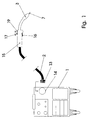
- the welding machine on which FIG. 1 is based exists from a basic assembly with a mobile frame 1 and one with a hose package 2 connected burner 3. This is here as electrical Shielding gas welding torch trained.
- the basic assembly 1, which the burner 3 assigned supply and Contains control devices is accordingly how is best seen in Figure 2, with an electrical Power section 4 for providing the welding energy, a protective gas source 5 for providing the Shielding gas and a wire feeder 6 for provision of the welding wire 7 and a central one Control unit 8 for controlling the aforementioned Supply organs equipped.
- the hose package 2 contains as further indicated in Figure 2, all of the Basic assembly 1 to supply lines leading to burner 3, here in the form of the forward and reverse branches 9a, 9b a control circuit, the welding current line 10, the Shielding gas line 11 and the welding wire line 12.
- a quick coupling is provided.
- the Plug 13 and the associated socket 14 are with the above Supply lines assigned to each other attachable coupling elements.
- the aforementioned switching and display device contains a button 16 for on and Switching off the power section 4 and a button 17 to increase or decrease the performance of the power section 4, i.e. the effective welding energy.
- the above Push buttons 16, 17 can be designed as slide switches be, which each have two switching positions, which the switch 16 on and off and assigned to the up or down control process at button 17 are. With the help of the buttons 16, 17 are assigned Switch operated. As indicated in FIG. 2, these are is arranged in a handle 15, integrated electronic circuit 18.
- the button 16 is a switch 16a assigned with the help of which Switching on and off is accomplished.
- the button 17 two switches 17a, 17b are assigned, of which the Switch 17a for increasing the welding energy and Switch 17b serve to lower the welding energy should.
- a display device is also on the handle 15 19 to display the current setting of the welding energy intended.
- the display device 19 contains a two-color lighting device by two in one common housing and arranged on a common chip, each have a different color LEDs 19a, 19b can be formed, the circuitry are integrated in the electronic circuit 18, as in FIG Figure 2 is indicated.
- One of the LEDs For example, the light emitting diode 19a can have a red color own and the highest setting of welding energy be assigned.
- the other light emitting diode 19b can, for example have green color and the lowest setting be assigned to the welding energy.
- In between the top and bottom setting is the Luminous intensity of the two LEDs similar to current setting can be changed, i.e. at one at the lowest level closer setting, the green one lights up LED 19b more and vice versa. In these intermediate positions Accordingly, one of the settings results corresponding mixed color of the entire two-color lighting device.
- the switches 16a, 17a, 17b and the light emitting diodes 19a, 19b are, as already mentioned above, by the in FIG schematically indicated electronic circuit 18 with each other linked within the control circuit 9a, 9b is arranged. This is used for provision the operating voltage and for signal transmission from the Central control unit 8 of the base module 1 for in the area of the burner provided electronic circuit 18 and vice versa. Accordingly, there is only one control circuit required of the inside of the plug coupling 13, 14 arranged contacts can run.
- control circuit 9a, 9b simultaneously as a signal flow line from the central control unit 8 of the basic assembly 1 for electronic switching on the burner side 18 and vice versa, the via the branch leading to the electronic circuit 18 9a and that to the central control unit 8 returning branch 9b of the control circuit each current modulated differently, i.e. it will different parameters of the respective current depending on the signal modulated.
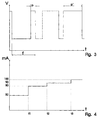
- the about the Branch 9a current pulsates, as indicated in Figure 3 with a constant frequency f between two Thresholds. The lower threshold is sufficient to to maintain the operating voltage.
- modulation the pulse width of the pulsating voltage is changed, as from a comparison of the pulse widths p and p ' can be seen.
- the burner electronics 18 the incoming pulse widths are used in control commands for the LEDs 19a, 19b converted as by the Converter 21 is indicated.
- the narrow pulse width p the lower extreme value and the wide pulse width p 'the upper extreme value of the welding energy.
- the narrow pulses When the narrow pulses are generated, they become Signals processed so that the green light emitting diode 19b shines.
- the wide pulses When the wide pulses are generated these processed so that the red LED 19a shines. In between, both shine with the respective one Adjusted intensity of welding energy so that a corresponding mixed color results.
- the signals returned by the electronics 18a to the central control unit 8 for controlling the power section 4 up or down are generated by changing the current strength.
- the switches 16a, 17a, 17b and the light-emitting diodes 19a, 19b are arranged in parallel current paths 22, each of which contains an associated current generator 23 which generates a fluctuation-free direct current and decouples the current from the Performs pulse width modulation.
- Current always flows through the light emitting diodes 19a, 19b. Via the switches 16a, 17a, 17b only when these switches are closed.
- the total strength of the current flowing through the return branch 9b of the control circuit accordingly depends, as indicated in FIG. 4, on the position of the individual switches 16a, 17a, 17b.
- the diode current is 50 milliamper, for example.
- the current assigned to switch 16a for switching the power section on and off should be 30 milliamper in the example shown, the current assigned to switch 17a for starting up the power section should be 20 milliamper and the current assigned to switch 17b for shutting down the power section should be 10 milliamper. Accordingly, when the switch 16a is closed and the switches 17a, 17b, 80 milliamper are open, when the switch 17b is additionally closed, 90 milliamper flow and when the switch 17b, as an alternative to the switch 17b, is closed, 100 milliamper flow. 4, the switch 16a is closed at the time t 1 . The two 17a, 17b are still open. At time t 2 , switch 17b is closed in order to control the welding energy again. Then, at time t 3, the switch 17b is opened and, at the same time, the switch 17a is closed in order to increase the welding energy.
- the total strength of each incoming stream is by a signal from the central control unit 8 upstream converter 24 recognized and in signals for the central control unit 8 which converts these signals converted into suitable commands for the power section 4. Since the current strength is the same in the entire circuit, the converter 24 somewhere in the forward or return load 9a, 9b of the control circuit. In the illustrated Example is the converter 24 with the PWM generator 20 the central control unit 8 combined into one unit. In parallel with the performance, the wire feed regulated and the shielding gas switched on and off.
Landscapes
- Engineering & Computer Science (AREA)
- Physics & Mathematics (AREA)
- Plasma & Fusion (AREA)
- Mechanical Engineering (AREA)
- Arc Welding Control (AREA)
- Electrical Discharge Machining, Electrochemical Machining, And Combined Machining (AREA)
- Lining Or Joining Of Plastics Or The Like (AREA)
- Lighting Device Outwards From Vehicle And Optical Signal (AREA)
- Threshing Machine Elements (AREA)
- Selective Calling Equipment (AREA)
Applications Claiming Priority (2)
| Application Number | Priority Date | Filing Date | Title |
|---|---|---|---|
| DE4313508A DE4313508A1 (de) | 1993-04-24 | 1993-04-24 | Arbeitsmaschine |
| DE4313508 | 1993-04-24 |
Publications (3)
| Publication Number | Publication Date |
|---|---|
| EP0622768A2 EP0622768A2 (de) | 1994-11-02 |
| EP0622768A3 EP0622768A3 (de) | 1995-01-11 |
| EP0622768B1 true EP0622768B1 (de) | 1999-06-30 |
Family
ID=6486313
Family Applications (1)
| Application Number | Title | Priority Date | Filing Date |
|---|---|---|---|
| EP94105826A Expired - Lifetime EP0622768B1 (de) | 1993-04-24 | 1994-04-15 | Elektrische Schweissmaschine mit einer Fernsteuerung |
Country Status (7)
| Country | Link |
|---|---|
| EP (1) | EP0622768B1 (da) |
| AT (1) | ATE181780T1 (da) |
| CZ (1) | CZ290260B6 (da) |
| DE (3) | DE9321354U1 (da) |
| DK (1) | DK0622768T3 (da) |
| ES (1) | ES2135502T3 (da) |
| GR (1) | GR3031403T3 (da) |
Families Citing this family (14)
| Publication number | Priority date | Publication date | Assignee | Title |
|---|---|---|---|---|
| AT406942B (de) * | 1999-01-15 | 2000-10-25 | Fronius Schweissmasch | Fernreglereinheit für ein schweissgerät oder eine stromquelle |
| DE102005033744A1 (de) * | 2005-07-15 | 2007-02-01 | Felix Politt | Handstück sowie Schweißdrahtzuführeinrichtung |
| EP2589454B1 (de) | 2011-11-04 | 2016-03-30 | Ewm Ag | Steuereinheit für ein Schweißgerät, Schweißbrenner mit einer Datenschnittstelle, und Schweißgerät mit solchen Einrichtungen |
| US10448692B2 (en) | 2015-03-06 | 2019-10-22 | Illinois Tool Works Inc. | Sensor assisted head mounted displays for welding |
| US10380911B2 (en) | 2015-03-09 | 2019-08-13 | Illinois Tool Works Inc. | Methods and apparatus to provide visual information associated with welding operations |
| US9977242B2 (en) | 2015-03-26 | 2018-05-22 | Illinois Tool Works Inc. | Control of mediated reality welding system based on lighting conditions |
| US10363632B2 (en) | 2015-06-24 | 2019-07-30 | Illinois Tool Works Inc. | Time of flight camera for welding machine vision |
| US10987749B2 (en) * | 2017-01-04 | 2021-04-27 | Illinois Tool Works Inc. | Methods and systems for indicating a schedule in a welding-type torch |
| US11213907B2 (en) | 2017-01-04 | 2022-01-04 | Illinois Tool Works Inc. | Methods and systems for selecting welding schedules in a welding-type torch |
| US11450233B2 (en) | 2019-02-19 | 2022-09-20 | Illinois Tool Works Inc. | Systems for simulating joining operations using mobile devices |
| US11521512B2 (en) | 2019-02-19 | 2022-12-06 | Illinois Tool Works Inc. | Systems for simulating joining operations using mobile devices |
| US11721231B2 (en) | 2019-11-25 | 2023-08-08 | Illinois Tool Works Inc. | Weld training simulations using mobile devices, modular workpieces, and simulated welding equipment |
| US12198568B2 (en) | 2019-11-25 | 2025-01-14 | Illinois Tool Works Inc. | Weld training simulations using mobile devices, modular workpieces, and simulated welding equipment |
| US11322037B2 (en) | 2019-11-25 | 2022-05-03 | Illinois Tool Works Inc. | Weld training simulations using mobile devices, modular workpieces, and simulated welding equipment |
Family Cites Families (7)
| Publication number | Priority date | Publication date | Assignee | Title |
|---|---|---|---|---|
| US4216368A (en) * | 1978-11-27 | 1980-08-05 | Delay Calvin J | Remote control device for arc welding |
| AT381663B (de) * | 1982-08-19 | 1986-11-10 | Elin Union Ag | Fernsteuereinrichtung fuer den lichtbogenschweissstrom einer gleichstromschweissquelle |
| CA1185329A (en) * | 1983-09-23 | 1985-04-09 | Ron Cox | Plural function control for hand-held arc welding torch |
| DE3615452A1 (de) * | 1986-05-07 | 1987-11-26 | Endress Hauser Gmbh Co | Anordnung zur signaluebertragung in einer messanordnung |
| DE8626928U1 (de) * | 1986-10-10 | 1986-12-11 | Wilhelm Merkle Schweißmaschinenbau GmbH, 8871 Kötz | Schneidmaschine |
| DE4121740A1 (de) * | 1990-07-06 | 1992-01-09 | Fronius Schweissmasch | Lichtbogenschweissmaschine mit ferneinsteller |
| FI920003A0 (fi) * | 1992-01-02 | 1992-01-02 | Kirsi Viitamaeki | Element i en brygga eller liknande. |
-
1993
- 1993-04-24 DE DE9321354U patent/DE9321354U1/de not_active Expired - Lifetime
- 1993-04-24 DE DE4313508A patent/DE4313508A1/de not_active Withdrawn
-
1994
- 1994-04-15 ES ES94105826T patent/ES2135502T3/es not_active Expired - Lifetime
- 1994-04-15 DE DE59408440T patent/DE59408440D1/de not_active Expired - Lifetime
- 1994-04-15 EP EP94105826A patent/EP0622768B1/de not_active Expired - Lifetime
- 1994-04-15 DK DK94105826T patent/DK0622768T3/da active
- 1994-04-15 AT AT94105826T patent/ATE181780T1/de active
- 1994-04-20 CZ CZ1994945A patent/CZ290260B6/cs not_active IP Right Cessation
-
1999
- 1999-09-30 GR GR990402494T patent/GR3031403T3/el unknown
Also Published As
| Publication number | Publication date |
|---|---|
| CZ290260B6 (cs) | 2002-06-12 |
| DE59408440D1 (de) | 1999-08-05 |
| CZ94594A3 (en) | 1994-12-15 |
| GR3031403T3 (en) | 2000-01-31 |
| DE9321354U1 (de) | 1997-10-16 |
| DE4313508A1 (de) | 1994-10-27 |
| ATE181780T1 (de) | 1999-07-15 |
| EP0622768A3 (de) | 1995-01-11 |
| EP0622768A2 (de) | 1994-11-02 |
| DK0622768T3 (da) | 2000-01-31 |
| ES2135502T3 (es) | 1999-11-01 |
Similar Documents
| Publication | Publication Date | Title |
|---|---|---|
| DE3743180C2 (da) | ||
| DE4121977C2 (de) | Medizinisches Instrument mit einem kontaktlosen Schalter zum Steuern externer Geräte | |
| DE9321354U1 (de) | Arbeitsmaschine | |
| EP2024125B1 (de) | Scheckkarten-fernregler mit elektrodenkontakten zur erhöhung und zur verringerung eines schweissparameters und mit einer anzeige | |
| DE3213313A1 (de) | Stellungsmesstastkopf | |
| EP1115498B1 (de) | Manuelle sprühbeschichtungspistole | |
| EP0313738A2 (de) | Verfahren zur bidirektionalen Uebertragung optischer Signale ueber Lichtwellenleiter | |
| DE10040713B4 (de) | Elektrischer Schalter | |
| EP0172454A1 (de) | Überwachungseinrichtung für Verkehrssignalanlagen | |
| EP1445987A1 (de) | Vorrichtung zur Ansteuerung einer Leuchte mit Licht in mindestens zwei unterschiedlichen Farben aussendenden LED | |
| DE4309527C2 (de) | Fernsteuer-Sendevorrichtung | |
| WO2018046342A1 (de) | Gurtschloss mit beleuchtung | |
| DE3307002C2 (de) | Vorrichtung zur manuellen Saugleistungssteuerung eines Staubsaugers | |
| DE10303450B4 (de) | Infrarot-LED-Treiberschaltung für Geräte mit Infrarot-Kommunikation | |
| DE4435353C2 (de) | Anordnung zur Fernsteuerung von Schweißgeräten | |
| EP0134425A2 (de) | Lichtwellenleitersteckvorrichtung | |
| DE2431119B2 (de) | Anordnung zur Anzeige der Stellung eines Stellgliedes | |
| DE3130383A1 (de) | Steuereinrichtung fuer eine elektronenstrahlquelle | |
| DE2850044C2 (de) | Schaltungsanordnung mit zumindest einer lichtemittierenden Diode | |
| DE3014214A1 (de) | Anordnung zur uebertragung digitaler signale auf einer uebertragungsstrecke | |
| DE3607670A1 (de) | Drehzahlsteller fuer elektromotorische antriebe von werkzeugen | |
| DD251288A1 (de) | Einrichtung zur drehzahleinstellung fuer ein zahnaerztliches behandlungsgeraet | |
| DE3825126A1 (de) | Verfahren zur bidirektionalen uebertragung optischer signale ueber einen lichtwellenleiter | |
| DE2905129A1 (de) | Schaltungsanordnung zum ein- und ausschalten von verbrauchern mittels eines tastschalters | |
| DE905399C (de) | Elektrische Fuehlersteuerung fuer Bearbeitungsmaschinen |
Legal Events
| Date | Code | Title | Description |
|---|---|---|---|
| PUAI | Public reference made under article 153(3) epc to a published international application that has entered the european phase |
Free format text: ORIGINAL CODE: 0009012 |
|
| AK | Designated contracting states |
Kind code of ref document: A2 Designated state(s): AT BE CH DE DK ES FR GB GR IE IT LI LU NL PT SE |
|
| PUAL | Search report despatched |
Free format text: ORIGINAL CODE: 0009013 |
|
| AK | Designated contracting states |
Kind code of ref document: A3 Designated state(s): AT BE CH DE DK ES FR GB GR IE IT LI LU NL PT SE |
|
| 17P | Request for examination filed |
Effective date: 19950310 |
|
| RAP1 | Party data changed (applicant data changed or rights of an application transferred) |
Owner name: MERKLE, WILHELM |
|
| 17Q | First examination report despatched |
Effective date: 19971022 |
|
| GRAG | Despatch of communication of intention to grant |
Free format text: ORIGINAL CODE: EPIDOS AGRA |
|
| GRAG | Despatch of communication of intention to grant |
Free format text: ORIGINAL CODE: EPIDOS AGRA |
|
| GRAH | Despatch of communication of intention to grant a patent |
Free format text: ORIGINAL CODE: EPIDOS IGRA |
|
| GRAH | Despatch of communication of intention to grant a patent |
Free format text: ORIGINAL CODE: EPIDOS IGRA |
|
| GRAA | (expected) grant |
Free format text: ORIGINAL CODE: 0009210 |
|
| AK | Designated contracting states |
Kind code of ref document: B1 Designated state(s): AT BE CH DE DK ES FR GB GR IE IT LI LU NL PT SE |
|
| REF | Corresponds to: |
Ref document number: 181780 Country of ref document: AT Date of ref document: 19990715 Kind code of ref document: T |
|
| REG | Reference to a national code |
Ref country code: CH Ref legal event code: EP |
|
| REF | Corresponds to: |
Ref document number: 59408440 Country of ref document: DE Date of ref document: 19990805 |
|
| REG | Reference to a national code |
Ref country code: IE Ref legal event code: FG4D Free format text: GERMAN |
|
| ET | Fr: translation filed | ||
| GBT | Gb: translation of ep patent filed (gb section 77(6)(a)/1977) |
Effective date: 19990922 |
|
| REG | Reference to a national code |
Ref country code: ES Ref legal event code: FG2A Ref document number: 2135502 Country of ref document: ES Kind code of ref document: T3 |
|
| REG | Reference to a national code |
Ref country code: PT Ref legal event code: SC4A Free format text: AVAILABILITY OF NATIONAL TRANSLATION Effective date: 19990831 |
|
| REG | Reference to a national code |
Ref country code: DK Ref legal event code: T3 |
|
| PLBE | No opposition filed within time limit |
Free format text: ORIGINAL CODE: 0009261 |
|
| STAA | Information on the status of an ep patent application or granted ep patent |
Free format text: STATUS: NO OPPOSITION FILED WITHIN TIME LIMIT |
|
| 26N | No opposition filed | ||
| REG | Reference to a national code |
Ref country code: IE Ref legal event code: FD4D |
|
| REG | Reference to a national code |
Ref country code: IE Ref legal event code: FD4D Ref document number: ERRATA: Incorrectly Country of ref document: IE |
|
| REG | Reference to a national code |
Ref country code: GB Ref legal event code: IF02 |
|
| PGFP | Annual fee paid to national office [announced via postgrant information from national office to epo] |
Ref country code: IE Payment date: 20050316 Year of fee payment: 12 |
|
| PGFP | Annual fee paid to national office [announced via postgrant information from national office to epo] |
Ref country code: BE Payment date: 20050321 Year of fee payment: 12 |
|
| PGFP | Annual fee paid to national office [announced via postgrant information from national office to epo] |
Ref country code: PT Payment date: 20050322 Year of fee payment: 12 |
|
| PGFP | Annual fee paid to national office [announced via postgrant information from national office to epo] |
Ref country code: LU Payment date: 20050401 Year of fee payment: 12 |
|
| PGFP | Annual fee paid to national office [announced via postgrant information from national office to epo] |
Ref country code: GR Payment date: 20050503 Year of fee payment: 12 |
|
| PGFP | Annual fee paid to national office [announced via postgrant information from national office to epo] |
Ref country code: CH Payment date: 20060227 Year of fee payment: 13 |
|
| PG25 | Lapsed in a contracting state [announced via postgrant information from national office to epo] |
Ref country code: IE Free format text: LAPSE BECAUSE OF NON-PAYMENT OF DUE FEES Effective date: 20060417 |
|
| PG25 | Lapsed in a contracting state [announced via postgrant information from national office to epo] |
Ref country code: LU Free format text: LAPSE BECAUSE OF NON-PAYMENT OF DUE FEES Effective date: 20060430 Ref country code: BE Free format text: LAPSE BECAUSE OF NON-PAYMENT OF DUE FEES Effective date: 20060430 |
|
| PG25 | Lapsed in a contracting state [announced via postgrant information from national office to epo] |
Ref country code: PT Free format text: LAPSE BECAUSE OF NON-PAYMENT OF DUE FEES Effective date: 20061016 |
|
| REG | Reference to a national code |
Ref country code: PT Ref legal event code: MM4A Free format text: LAPSE DUE TO NON-PAYMENT OF FEES Effective date: 20061016 |
|
| REG | Reference to a national code |
Ref country code: IE Ref legal event code: MM4A |
|
| REG | Reference to a national code |
Ref country code: CH Ref legal event code: PL |
|
| BERE | Be: lapsed |
Owner name: *MERKLE WILHELM Effective date: 20060430 |
|
| PG25 | Lapsed in a contracting state [announced via postgrant information from national office to epo] |
Ref country code: LI Free format text: LAPSE BECAUSE OF NON-PAYMENT OF DUE FEES Effective date: 20070430 Ref country code: CH Free format text: LAPSE BECAUSE OF NON-PAYMENT OF DUE FEES Effective date: 20070430 |
|
| PGFP | Annual fee paid to national office [announced via postgrant information from national office to epo] |
Ref country code: FR Payment date: 20080305 Year of fee payment: 15 |
|
| PG25 | Lapsed in a contracting state [announced via postgrant information from national office to epo] |
Ref country code: GR Free format text: LAPSE BECAUSE OF NON-PAYMENT OF DUE FEES Effective date: 20061102 |
|
| PGFP | Annual fee paid to national office [announced via postgrant information from national office to epo] |
Ref country code: ES Payment date: 20090407 Year of fee payment: 16 Ref country code: DK Payment date: 20090330 Year of fee payment: 16 |
|
| PGFP | Annual fee paid to national office [announced via postgrant information from national office to epo] |
Ref country code: SE Payment date: 20090402 Year of fee payment: 16 |
|
| REG | Reference to a national code |
Ref country code: FR Ref legal event code: ST Effective date: 20091231 |
|
| PG25 | Lapsed in a contracting state [announced via postgrant information from national office to epo] |
Ref country code: FR Free format text: LAPSE BECAUSE OF NON-PAYMENT OF DUE FEES Effective date: 20091222 |
|
| EUG | Se: european patent has lapsed | ||
| REG | Reference to a national code |
Ref country code: DK Ref legal event code: EBP |
|
| PG25 | Lapsed in a contracting state [announced via postgrant information from national office to epo] |
Ref country code: DK Free format text: LAPSE BECAUSE OF NON-PAYMENT OF DUE FEES Effective date: 20100503 |
|
| REG | Reference to a national code |
Ref country code: ES Ref legal event code: FD2A Effective date: 20110715 |
|
| PG25 | Lapsed in a contracting state [announced via postgrant information from national office to epo] |
Ref country code: ES Free format text: LAPSE BECAUSE OF NON-PAYMENT OF DUE FEES Effective date: 20110705 |
|
| PG25 | Lapsed in a contracting state [announced via postgrant information from national office to epo] |
Ref country code: ES Free format text: LAPSE BECAUSE OF NON-PAYMENT OF DUE FEES Effective date: 20100416 |
|
| PGFP | Annual fee paid to national office [announced via postgrant information from national office to epo] |
Ref country code: NL Payment date: 20120425 Year of fee payment: 19 |
|
| PGFP | Annual fee paid to national office [announced via postgrant information from national office to epo] |
Ref country code: GB Payment date: 20120423 Year of fee payment: 19 |
|
| PG25 | Lapsed in a contracting state [announced via postgrant information from national office to epo] |
Ref country code: SE Free format text: LAPSE BECAUSE OF NON-PAYMENT OF DUE FEES Effective date: 20100416 |
|
| PGFP | Annual fee paid to national office [announced via postgrant information from national office to epo] |
Ref country code: IT Payment date: 20120428 Year of fee payment: 19 |
|
| PGFP | Annual fee paid to national office [announced via postgrant information from national office to epo] |
Ref country code: AT Payment date: 20120420 Year of fee payment: 19 |
|
| REG | Reference to a national code |
Ref country code: DE Ref legal event code: R084 Ref document number: 59408440 Country of ref document: DE Effective date: 20130205 |
|
| PGFP | Annual fee paid to national office [announced via postgrant information from national office to epo] |
Ref country code: DE Payment date: 20130430 Year of fee payment: 20 |
|
| REG | Reference to a national code |
Ref country code: NL Ref legal event code: V1 Effective date: 20131101 |
|
| REG | Reference to a national code |
Ref country code: AT Ref legal event code: MM01 Ref document number: 181780 Country of ref document: AT Kind code of ref document: T Effective date: 20130430 |
|
| GBPC | Gb: european patent ceased through non-payment of renewal fee |
Effective date: 20130415 |
|
| PG25 | Lapsed in a contracting state [announced via postgrant information from national office to epo] |
Ref country code: GB Free format text: LAPSE BECAUSE OF NON-PAYMENT OF DUE FEES Effective date: 20130415 Ref country code: AT Free format text: LAPSE BECAUSE OF NON-PAYMENT OF DUE FEES Effective date: 20130430 |
|
| PG25 | Lapsed in a contracting state [announced via postgrant information from national office to epo] |
Ref country code: IT Free format text: LAPSE BECAUSE OF NON-PAYMENT OF DUE FEES Effective date: 20130415 Ref country code: NL Free format text: LAPSE BECAUSE OF NON-PAYMENT OF DUE FEES Effective date: 20131101 |
|
| REG | Reference to a national code |
Ref country code: DE Ref legal event code: R071 Ref document number: 59408440 Country of ref document: DE |
|
| REG | Reference to a national code |
Ref country code: DE Ref legal event code: R071 Ref document number: 59408440 Country of ref document: DE |
|
| PG25 | Lapsed in a contracting state [announced via postgrant information from national office to epo] |
Ref country code: DE Free format text: LAPSE BECAUSE OF EXPIRATION OF PROTECTION Effective date: 20140416 |