EP0622812B1 - Leistungswiderstand mit natürlicher Konvektion - Google Patents
Leistungswiderstand mit natürlicher Konvektion Download PDFInfo
- Publication number
- EP0622812B1 EP0622812B1 EP94400909A EP94400909A EP0622812B1 EP 0622812 B1 EP0622812 B1 EP 0622812B1 EP 94400909 A EP94400909 A EP 94400909A EP 94400909 A EP94400909 A EP 94400909A EP 0622812 B1 EP0622812 B1 EP 0622812B1
- Authority
- EP
- European Patent Office
- Prior art keywords
- flanges
- resistor according
- strip
- comb
- resistive
- Prior art date
- Legal status (The legal status is an assumption and is not a legal conclusion. Google has not performed a legal analysis and makes no representation as to the accuracy of the status listed.)
- Expired - Lifetime
Links
- 239000012212 insulator Substances 0.000 claims description 8
- 238000009423 ventilation Methods 0.000 claims description 6
- 229910052751 metal Inorganic materials 0.000 claims description 5
- 230000000712 assembly Effects 0.000 claims 7
- 238000000429 assembly Methods 0.000 claims 7
- 210000001520 comb Anatomy 0.000 abstract description 24
- 239000000919 ceramic Substances 0.000 description 4
- 230000000694 effects Effects 0.000 description 3
- 238000012423 maintenance Methods 0.000 description 3
- 239000002184 metal Substances 0.000 description 3
- 238000001816 cooling Methods 0.000 description 2
- 125000006850 spacer group Chemical group 0.000 description 2
- 239000010935 stainless steel Substances 0.000 description 2
- 229910001220 stainless steel Inorganic materials 0.000 description 2
- VYZAMTAEIAYCRO-UHFFFAOYSA-N Chromium Chemical compound [Cr] VYZAMTAEIAYCRO-UHFFFAOYSA-N 0.000 description 1
- 229910000599 Cr alloy Inorganic materials 0.000 description 1
- 229910000990 Ni alloy Inorganic materials 0.000 description 1
- 238000005273 aeration Methods 0.000 description 1
- 239000011651 chromium Substances 0.000 description 1
- 229910052878 cordierite Inorganic materials 0.000 description 1
- JSKIRARMQDRGJZ-UHFFFAOYSA-N dimagnesium dioxido-bis[(1-oxido-3-oxo-2,4,6,8,9-pentaoxa-1,3-disila-5,7-dialuminabicyclo[3.3.1]nonan-7-yl)oxy]silane Chemical compound [Mg++].[Mg++].[O-][Si]([O-])(O[Al]1O[Al]2O[Si](=O)O[Si]([O-])(O1)O2)O[Al]1O[Al]2O[Si](=O)O[Si]([O-])(O1)O2 JSKIRARMQDRGJZ-UHFFFAOYSA-N 0.000 description 1
- 238000010438 heat treatment Methods 0.000 description 1
- 238000009434 installation Methods 0.000 description 1
- 230000014759 maintenance of location Effects 0.000 description 1
- 229910000623 nickel–chromium alloy Inorganic materials 0.000 description 1
- 238000013021 overheating Methods 0.000 description 1
- 230000000149 penetrating effect Effects 0.000 description 1
- 230000008646 thermal stress Effects 0.000 description 1
- 238000003466 welding Methods 0.000 description 1
Images


Classifications
-
- H—ELECTRICITY
- H01—ELECTRIC ELEMENTS
- H01C—RESISTORS
- H01C1/00—Details
- H01C1/01—Mounting; Supporting
- H01C1/014—Mounting; Supporting the resistor being suspended between and being supported by two supporting sections
-
- H—ELECTRICITY
- H01—ELECTRIC ELEMENTS
- H01C—RESISTORS
- H01C3/00—Non-adjustable metal resistors made of wire or ribbon, e.g. coiled, woven or formed as grids
- H01C3/10—Non-adjustable metal resistors made of wire or ribbon, e.g. coiled, woven or formed as grids the resistive element having zig-zag or sinusoidal configuration
Definitions
- the present invention relates to a power resistor with natural convection.
- rheostats are in the form of boxes which are combined to obtain the desired total resistance.
- Each box has a resistive tape generally made from an alloy of nickel and chromium.
- the rheostat is sized to optimize the following two main characteristics: the ohmic value and the thermal power to be dissipated.
- the air heats up on contact with the rheostat and is discharged to the outside.
- the resistance elements consist of a calibrated ribbon, rolled on edge and supported by guides, ceramic insulators.
- the helical shape given to the ribbon is intended to provide good cooling to the rheostat.
- the assembly is designed to allow free expansion of the heating elements.
- these resistors are mounted in the open air, either under the body or on the roof.
- the drawback of this type of resistance is that the propeller has a high self-value: a propeller can have an inductance of 100 ⁇ H and a complete rheostat can have ten propellers. These resistors cannot therefore function in association with modern power electronics circuits. It should indeed the complete rheostat has an inductance not exceeding 20 ⁇ H.
- the resistive tape consists of strips folded in a zigzag and welded end to end.
- the mounting of the ribbon in its box must allow maximum heat exchange between the ribbon and the cooling air flow, ensure the mechanical retention of the ribbon subjected to the effects of thermal expansion and prevent short-circuits between parts of the ribbon in screw opposite.
- the box is in the form of a flat parallelepiped closed on its four vertical faces by plates intended to support the mechanical holding elements of the tape, the insulating elements and the electrical connection terminals. Ventilation is carried out by forced passage of air between the open upper and lower faces.
- the present invention proposes a power resistor whose resistive strip is of the type used for rheostats cooled by forced ventilation, but whose structure is such that it allows excellent natural ventilation of the resistance. It is then possible, for the same volume, to replace the helical rheostats with rheostats according to the invention and to dissipate the same power.
- the power resistor according to the invention must also be of low cost, of easy assembly, not requiring in particular manual intervention between the folds of the resistive strip.
- the invention therefore relates to a power resistor cooled by natural convection comprising at least at least one resistive tape placed in a box ensuring its maintenance and supporting the electrical connections to the tape, the resistive tape being maintained by means of comb supports retaining the resistive tape by its longitudinal edges, disposed between the teeth of insulating combs mounted on said comb supports, the box being made up of only two flanges braced by some of the comb supports, the other comb supports being mounted floating between the flanges in order to avoid deforming the flanges under the effect of thermal expansion transmitted by the comb holders.
- the resistance may include two resistive tapes superimposed separated by common comb supports.
- a common comb support may have a cylindrical insulating comb pierced with an axial hole in which engages a rod supported at its two ends by the flanges of the box.
- Each resistive tape can advantageously be a strip folded in a zigzag.
- the strip can be formed by metallic elements forming one or more folds, these elements being welded end to end to constitute the strip.
- Each resistive tape can advantageously be a thick tape. This gives the tape good rigidity and thus avoids having to emboss it and it is not useful to equip it with insulating pins to prevent short-circuits between opposite parts.
- the flanges can be fitted with insulating sleeves located on the inner side of the box. This avoids a possible short circuit between the flanges and the resistive tape.
- the flanges are advantageously provided with lugs intended for fixing the box.
- the electrical connections can be fixed to the flanges by means of insulators.
- the flanges are preferably pierced with ventilation holes. These holes also make it possible to lighten them.
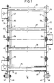
- Figures 1 to 3 illustrate a power resistor usable as a power rheostat in rail traction.
- the resistance comprises two parallel flanges 31 and 32 of rectangular shape.
- the flanges are braced by four comb supports each connecting a corner of a flange to the corner opposite the other flange.
- Figure 1 shows two upper comb supports 33 and 34 screwed onto the flanges 31 and 32.
- Figure 2 shows one of the two lower comb supports 35 serving as a spacer.
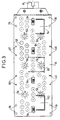
- Figure 3 shows on the flange 31 the location of the holes 36 used for fixing the comb supports playing the role of spacer.
- the box has two other intermediate comb supports 37 and 38 on its upper face and between the comb supports 33 and 34.
- Two other non-visible intermediate comb supports correspond to the comb supports 37 and 38 but on the underside of the box.
- These intermediate comb supports of the upper and lower faces are screwed onto the flange 32.
- the references 39 show the location of the holes used for screwing the comb supports 37 and 38.
- These comb supports are not fixed to the flange 31 but are simply connected to this flange by pinned pins passing through holes in locations referenced 40 of the flange 31.
- At ambient temperature there is a clearance between the flange 31 and the end plates 41 and 42 of the intermediate comb supports 37 and 38. This clearance prevents the flanges 31 and 32 from being deformed when the comb supports 37 and 38 expand.
- the resistor illustrated in FIGS. 1 to 3 comprises two resistive tapes 43 and 44 superimposed.
- Each resistive tape is formed by a band folded in a zigzag and extending from one flange to another, the folds being parallel to the flanges.
- the comb supports 33, 34, 35, 37 and 38 are therefore arranged transversely with respect to the folds of the resistive tapes.
- the box also includes comb supports located in the median plane between the upper and lower faces of the box to maintain the resistive tapes 43 and 44 at this level.
- FIGS. 1 and 2 show one of these median comb supports referenced 45. These median comb supports are mounted floating relative to the flanges 31 and 32.
- connection 46 has two electrical connections intended to insert it into an electrical circuit.
- Figure 1 shows these connections 46 and 47 fixed via insulators to the flanges 31 and 32.
- Each connection 46 or 47 is fixed to the corresponding flange by two insulators. They allow the resistive tapes to be connected in parallel.
- the connection 46 has a branch 50 welded on the one hand to one end of the upper resistive strip 43 and fixed on the other hand to the flange 31 by an insulator 48.
- the connection 46 has another branch 51 welded to on the one hand on one end of the lower resistive strip 44 and fixed on the other hand on the flange 31 by an insulator 52.
- the same goes for the connection 47 whose FIG. 1 shows only the insulator 49 fixing its upper branch to the flange 32.
- the box has three fixing lugs allowing the installation of the resistance in an equipment.
- Two tabs 53 and 54 are welded to the flange 31 and a tab 55 is welded to the flange 32.
- the assembly of these fixing lugs delimits a support triangle for the box.
- the flanges 31 and 32 are pierced with holes allowing the housing of insulating sleeves 56 preventing any untimely short-circuit between the flanges and the resistive tapes.
- the resistive tapes are for example made of a nickel-chromium alloy. By choosing them sufficiently thick (for example 1.2mm thick), they are provided with good rigidity which avoids excessive deformation during thermal expansion.
- Each strip can be formed by butt welding of resistive strip elements, each element having a W shape, that is to say comprising two plies.
- Figure 1 shows under reference 57 a weld zone between two end to end elements.
- the flanges are pierced with holes 58 (see FIG. 3) allowing better aeration of the resistance and also a reduction in the weight of the box.
- the upper and lower comb supports can be of the type illustrated in FIGS. 4 to 6.
- FIG. 4 shows an elementary comb 1 made of insulating ceramic, for example soapstone or cordierite. It is provided in the lower part with two lateral grooves 2 and 3 made over its entire length. Its upper part is provided with teeth 4 between which the resistive tape will be placed. Note that one end of the comb, the end 5, has only its lower part while the other end, the end 6, has only its upper part.
- Figure 5 shows a full comb holder. It comprises a metal support 10 which is a U-shaped section stainless steel profile having edges 11, 12 folded inwards.
- the metal support 10 is provided with end plates 13, 14 arranged transversely. These plates, also made of stainless steel, are welded to the support 10.
- the plate 13 closes the opening that the support has at this end.
- the plate 14 on the other hand has a cutout 15 making it possible to leave free the opening which the support has at this end (see FIG. 6).
- the plates 13 and 14 allow the fixing of the support 10 on the flanges.
- the plate 13 has two tapped holes 16 allowing its fixing by screwing on the flange 32.
- the plate 14 also includes tapped holes for fixing on the flange 31 when the comb supports are those placed in the corners of the flanges.
- the plate 14 has two holes 17 allowing a connection with a certain clearance with respect to the flange 31 by means of a pinned pin. This clearance allows the support 10 to expand under the effect of thermal stresses without deforming the structure of the rheostat and without deforming itself.
- the assembly of the elementary combs on the support is done quickly and easily by sliding the elementary combs in the support from its open end, the folded edges 11, 12 of the support penetrating into the grooves 2 and 3 of the combs.
- the end plate 13 serves as a stop for the elementary combs.
- the comb support comprises combs 1 identical to each other and end combs 21 and 22.
- the combs 1 are placed end to end so that the end 6 of a comb overlaps the end 5 of the adjacent comb.
- the end combs of the support 21 and 22 are different from the combs 1.
- the end of the comb 22 adjacent to the plate 13 and the end of the comb 21 adjacent to the plate 14 do not have to be conjugated with ends of adjacent combs. However, their other ends have shapes allowing an overlap with the adjacent combs 1.
- the lengths of the elementary combs are provided so that, whatever the operating temperature of the rheostat, there is always an overlap of two adjacent combs. Dielectric protection against electrical leakage lines between resistive tape and comb support is therefore always ensured.
- the elementary combs including the support end combs, can be of different lengths so as to make all the possible combinations.
- the median comb supports are mounted floating relative to the flanges 31 and 32.
- FIG. 2 details the constitution of a median comb support 45.
- This comprises a succession of elementary insulating ceramic combs such as the combs 61 and 62 of tubular shape. They are pierced with an axial hole allowing the passage of a metal rod 63 long enough to pass through the two flanges.
- Omega-shaped parts 64 each have their central part housed in a rectangular opening made in the flanges 31 and 32 and are therefore locked in rotation. The rods 63 open into holes provided in the central parts of the parts 64 and are blocked in translation by sets of washers and keys.
- Combs such as those referenced 61 and 62, are provided with an internal flat at each opening of their axial hole. Side flange 32, the piece 64 partially penetrates the axial hole of the comb and is housed in a flat of conjugate shape. Between two successive combs, such as the combs 61 and 62, an insulating ceramic intermediate piece is housed in the cavity formed by the flats facing the combs 61 and 62 and blocks any possibility of rotation around the rod 63 d 'one comb in relation to the other. The entire median comb support cannot therefore rotate on itself.
Landscapes
- Engineering & Computer Science (AREA)
- Microelectronics & Electronic Packaging (AREA)
- Details Of Resistors (AREA)
- Diaphragms For Electromechanical Transducers (AREA)
- Thermotherapy And Cooling Therapy Devices (AREA)
- Battery Mounting, Suspending (AREA)
- Professional, Industrial, Or Sporting Protective Garments (AREA)
- Surface Heating Bodies (AREA)
Claims (10)
- Durch natürliche Konvektion gekühlter Leistungswiderstand, mit mindestens einem Widerstandsband (43, 44), das in einem aus zwei Flanschen (31, 32) bestehenden Kasten angeordnet ist, der den Halt des Widerstandsbands mittels Kammträgern gewährleistet und elektrische Anschlüsse für das Widerstandsband trägt, dadurch gekennzeichnet, daß der Kasten nur über bestimmte der Kammträger (33, 34, 35) zusammengehalten wird, während die anderen Kammträger (37, 38, 45) flottierend zwischen den Flanschen abgeordnet sind, so daß die Flansche nicht unter der Wirkung von durch die Kammträger übertragenen Wärmeausdehnungen verformt werden, wobei die alle Kammträger (33, 34, 35, 37, 38, 45) das Widerstandsband an dessen Längsrändern halten, die zwischen den Zinken (4) der auf den Kammträgern montierten isolierenden Kämme (1) liegen.
- Widerstand nach Anspruch 1, dadurch gekennzeichnet, daß er zwei übereinanderliegende Widerstandsbänder (43, 44) aufweist, die durch gemeinsame Kammträger (45) getrennt gehalten werden.
- Widerstand nach Anspruch 2, dadurch gekennzeichnet, daß ein gemeinsamer Kammträger (45) einen isolierenden zylindrischen Kamm (61, 62) aufweist, der ein axiales Loch besitzt, in das ein Stab (63) eingefügt ist, der an seinen beiden Enden von den Flanschen (31, 32) des Kastens getragen wird.
- Widerstand nach einem beliebigen der Ansprüche 1 bis 3, dadurch gekennzeichnet, daß jedes Widerstandsband ein zickzackförmig gefaltetes Band ist.
- Widerstand nach Anspruch 4, dadurch gekennzeichnet, daß das Band aus Metallelementen bestehen, die eine oder mehrere Falten bilden, und daß diese Elemente endseitig aneinandergeschweißt sind, um das Band zu bilden.
- Widerstand nach einem beliebigen der Ansprüche 1 bis 5, dadurch gekennzeichnet, daß jedes Widerstandsband ein dickes Band ist.
- Widerstand nach einem beliebigen der Ansprüche 1 bis 6, dadurch gekennzeichnet, daß die Flansche isolierende Hülsen (56) aufweisen, die auf der Innenseite des Kastens angeordnet sind.
- Widerstand nach einem beliebigen der Ansprüche 1 bis 7, dadurch gekennzeichnet, daß die Flansche Laschen (53, 54, 55) besitzen, die zur Befestigung des Kastens dienen.
- Widerstand nach einem beliebigen der Ansprüche 1 bis 8, dadurch gekennzeichnet, daß die elektrischen verbindungen (46, 47) an den Flanschen über Isolatoren (48, 49, 52) befestigt sind.
- Widerstand nach einem beliebigen der vorhergehenden Ansprüche, dadurch gekennzeichnet, daß die Flansche (31, 32) Luftlöcher (58) besitzen.
Applications Claiming Priority (2)
| Application Number | Priority Date | Filing Date | Title |
|---|---|---|---|
| FR9305088 | 1993-04-29 | ||
| FR9305088A FR2704682B1 (fr) | 1993-04-29 | 1993-04-29 | Résistance de puissance à convection naturelle. |
Publications (2)
| Publication Number | Publication Date |
|---|---|
| EP0622812A1 EP0622812A1 (de) | 1994-11-02 |
| EP0622812B1 true EP0622812B1 (de) | 1996-05-15 |
Family
ID=9446581
Family Applications (1)
| Application Number | Title | Priority Date | Filing Date |
|---|---|---|---|
| EP94400909A Expired - Lifetime EP0622812B1 (de) | 1993-04-29 | 1994-04-27 | Leistungswiderstand mit natürlicher Konvektion |
Country Status (6)
| Country | Link |
|---|---|
| EP (1) | EP0622812B1 (de) |
| KR (1) | KR100297479B1 (de) |
| AT (1) | ATE138221T1 (de) |
| DE (1) | DE69400184T2 (de) |
| ES (1) | ES2086988T3 (de) |
| FR (1) | FR2704682B1 (de) |
Families Citing this family (6)
| Publication number | Priority date | Publication date | Assignee | Title |
|---|---|---|---|---|
| FR2740923B1 (fr) * | 1995-11-08 | 1997-12-19 | Alsthom Cge Alcatel | Rheostat de demarrage et/ou de freinage permettant la dissipation thermique de la puissance electrique le parcourant |
| GB9924903D0 (en) * | 1999-10-22 | 1999-12-22 | Eaton Ltd | Cooling resistor banks |
| KR100977184B1 (ko) * | 2010-04-30 | 2010-08-20 | 백용호 | 철도 차량용 코일저항기 |
| CN103280282B (zh) * | 2013-04-24 | 2016-04-13 | 北京天诚同创电气有限公司 | 用于风力发电机变流器的制动电阻 |
| DE102020202249A1 (de) * | 2020-02-21 | 2021-08-26 | Siemens Mobility GmbH | Bremswiderstand für ein Fahrzeug |
| CN113704971B (zh) * | 2021-07-30 | 2022-11-18 | 西安铁路信号有限责任公司 | 一种多层电阻带等温升计算方法 |
Family Cites Families (5)
| Publication number | Priority date | Publication date | Assignee | Title |
|---|---|---|---|---|
| DE967834C (de) * | 1940-08-24 | 1957-12-19 | Siemens Ag | Widerstandsanordnung, insbesondere fuer Anlasser |
| US3697923A (en) * | 1971-09-13 | 1972-10-10 | Hubbell Inc Harvey | Ribbon resistor with supporting means |
| US4100526A (en) * | 1977-02-24 | 1978-07-11 | Mosebach Manufacturing Company | Grid resistor |
| DE4008422A1 (de) * | 1990-03-16 | 1991-09-19 | Asea Brown Boveri | Leistungswiderstand |
| US5165052A (en) * | 1991-04-25 | 1992-11-17 | Mosebach Manufacturing Company | Slide-in resistor grid |
-
1993
- 1993-04-29 FR FR9305088A patent/FR2704682B1/fr not_active Expired - Fee Related
-
1994
- 1994-04-27 ES ES94400909T patent/ES2086988T3/es not_active Expired - Lifetime
- 1994-04-27 DE DE69400184T patent/DE69400184T2/de not_active Expired - Fee Related
- 1994-04-27 AT AT94400909T patent/ATE138221T1/de not_active IP Right Cessation
- 1994-04-27 EP EP94400909A patent/EP0622812B1/de not_active Expired - Lifetime
- 1994-04-28 KR KR1019940009079A patent/KR100297479B1/ko not_active Expired - Fee Related
Also Published As
| Publication number | Publication date |
|---|---|
| ATE138221T1 (de) | 1996-06-15 |
| DE69400184D1 (de) | 1996-06-20 |
| KR100297479B1 (ko) | 2001-10-24 |
| DE69400184T2 (de) | 1996-10-02 |
| FR2704682A1 (fr) | 1994-11-04 |
| FR2704682B1 (fr) | 1995-06-02 |
| EP0622812A1 (de) | 1994-11-02 |
| ES2086988T3 (es) | 1996-07-01 |
Similar Documents
| Publication | Publication Date | Title |
|---|---|---|
| EP1561075B1 (de) | Kondensationswärmetauscher mit kunststoffmantel | |
| EP0119502A1 (de) | Thermoelektrische Anlage | |
| EP3647188B1 (de) | Hitzeschild für gebremstes rad eines luftfahrzeugs | |
| FR2654978A1 (fr) | Piece de raccordement du type a resistance electrique perfectionnee pour la reunion par thermosoudage d'elements en matiere plastique. | |
| EP0373052A1 (de) | Trägerelement für eine Übertragungsleitung, insbesondere vom Streifenleitungstyp | |
| FR2995127A1 (fr) | Noyau magnetique pour un composant magnetique a bobinage, comportant des moyens de refroidissement perfectionnes | |
| EP0039049B1 (de) | Abstandsstück für statorische Kühlkanäle einer dynamoelektrischen Kraftmaschine | |
| FR2714203A1 (fr) | Ligne à haute tension à isolation gazeuse pour longue distance. | |
| EP0625284A1 (de) | Flachsicherung für hohe nennströme | |
| EP0622812A1 (de) | Leistungswiderstand mit natürlicher Konvektion | |
| EP0017082A1 (de) | Thermoelektrische Vorrichtung zum Wärmeaustausch zwischen einem ersten Gasfluidum und einem zweiten Fluidum | |
| EP4111822A1 (de) | Vorrichtung zum erwärmen eines produkts durch querstrominduktion | |
| FR2526535A1 (fr) | Plaque de blindage, notamment pour blindage allege | |
| WO2021116580A1 (fr) | Dispositif chauffant électrique pour véhicule automobile | |
| EP0622813B1 (de) | Widerstandselement für Leistungswiderstand | |
| FR2958790A1 (fr) | Organe intercalaire pour une bobine de transformateur, bobine comportant un tel organe, partie active et transformateur comprenant une telle partie active. | |
| FR2630612A1 (fr) | Dispositif de protection des poles d'inducteurs et inducteur pourvu de ce dispositif | |
| FR3089067A1 (fr) | Coffre de batterie et systeme de batterie modulaire | |
| EP0618593B1 (de) | Halterungsanordnung für Widerstandsbänder für Leistungswiderstände | |
| FR3104687A1 (fr) | Dispositif thermique pour véhicule automobile | |
| FR2462712A1 (fr) | Dispositif de mesure de tensions alternatives elevees dans des installations de distribution haute tension | |
| FR3075333A1 (fr) | Echangeur de chaleur pour vehicule | |
| EP0232661B1 (de) | Elektromagnetische Pumpe für leitende Flüssigkeit mit Zurückdrängung durch magnetische Abstossung | |
| EP2068106A1 (de) | Wellrippen mit Kiemen für einen Wärmetauscher | |
| FR2631427A1 (fr) | Element chauffant pour un radiateur electrique utilise pour le chauffage de locaux, notamment de type continu |
Legal Events
| Date | Code | Title | Description |
|---|---|---|---|
| PUAI | Public reference made under article 153(3) epc to a published international application that has entered the european phase |
Free format text: ORIGINAL CODE: 0009012 |
|
| AK | Designated contracting states |
Kind code of ref document: A1 Designated state(s): AT BE CH DE ES FR GB IT LI SE |
|
| 17P | Request for examination filed |
Effective date: 19950303 |
|
| 17Q | First examination report despatched |
Effective date: 19950921 |
|
| GRAH | Despatch of communication of intention to grant a patent |
Free format text: ORIGINAL CODE: EPIDOS IGRA |
|
| GRAA | (expected) grant |
Free format text: ORIGINAL CODE: 0009210 |
|
| AK | Designated contracting states |
Kind code of ref document: B1 Designated state(s): AT BE CH DE ES FR GB IT LI SE |
|
| REF | Corresponds to: |
Ref document number: 138221 Country of ref document: AT Date of ref document: 19960615 Kind code of ref document: T |
|
| ITF | It: translation for a ep patent filed | ||
| REG | Reference to a national code |
Ref country code: CH Ref legal event code: NV Representative=s name: GEC ALSTHOM (SUISSE) S.A. DEPARTEMENT DES BREVETS |
|
| REF | Corresponds to: |
Ref document number: 69400184 Country of ref document: DE Date of ref document: 19960620 |
|
| REG | Reference to a national code |
Ref country code: ES Ref legal event code: FG2A Ref document number: 2086988 Country of ref document: ES Kind code of ref document: T3 |
|
| GBT | Gb: translation of ep patent filed (gb section 77(6)(a)/1977) |
Effective date: 19960711 |
|
| PLBE | No opposition filed within time limit |
Free format text: ORIGINAL CODE: 0009261 |
|
| STAA | Information on the status of an ep patent application or granted ep patent |
Free format text: STATUS: NO OPPOSITION FILED WITHIN TIME LIMIT |
|
| 26N | No opposition filed | ||
| REG | Reference to a national code |
Ref country code: GB Ref legal event code: IF02 |
|
| PGFP | Annual fee paid to national office [announced via postgrant information from national office to epo] |
Ref country code: ES Payment date: 20090422 Year of fee payment: 16 |
|
| PGFP | Annual fee paid to national office [announced via postgrant information from national office to epo] |
Ref country code: SE Payment date: 20090416 Year of fee payment: 16 Ref country code: IT Payment date: 20090428 Year of fee payment: 16 Ref country code: FR Payment date: 20090414 Year of fee payment: 16 Ref country code: DE Payment date: 20090422 Year of fee payment: 16 Ref country code: AT Payment date: 20090416 Year of fee payment: 16 |
|
| PGFP | Annual fee paid to national office [announced via postgrant information from national office to epo] |
Ref country code: BE Payment date: 20090528 Year of fee payment: 16 |
|
| PGFP | Annual fee paid to national office [announced via postgrant information from national office to epo] |
Ref country code: CH Payment date: 20090417 Year of fee payment: 16 |
|
| PGFP | Annual fee paid to national office [announced via postgrant information from national office to epo] |
Ref country code: GB Payment date: 20090421 Year of fee payment: 16 |
|
| BERE | Be: lapsed |
Owner name: GEC ALSTHOM TRANSPORT SA Effective date: 20100430 |
|
| EUG | Se: european patent has lapsed | ||
| REG | Reference to a national code |
Ref country code: CH Ref legal event code: PL |
|
| GBPC | Gb: european patent ceased through non-payment of renewal fee |
Effective date: 20100427 |
|
| REG | Reference to a national code |
Ref country code: FR Ref legal event code: ST Effective date: 20101230 |
|
| PG25 | Lapsed in a contracting state [announced via postgrant information from national office to epo] |
Ref country code: AT Free format text: LAPSE BECAUSE OF NON-PAYMENT OF DUE FEES Effective date: 20100427 |
|
| PG25 | Lapsed in a contracting state [announced via postgrant information from national office to epo] |
Ref country code: LI Free format text: LAPSE BECAUSE OF NON-PAYMENT OF DUE FEES Effective date: 20100430 Ref country code: DE Free format text: LAPSE BECAUSE OF NON-PAYMENT OF DUE FEES Effective date: 20101103 Ref country code: CH Free format text: LAPSE BECAUSE OF NON-PAYMENT OF DUE FEES Effective date: 20100430 |
|
| PG25 | Lapsed in a contracting state [announced via postgrant information from national office to epo] |
Ref country code: IT Free format text: LAPSE BECAUSE OF NON-PAYMENT OF DUE FEES Effective date: 20100427 Ref country code: GB Free format text: LAPSE BECAUSE OF NON-PAYMENT OF DUE FEES Effective date: 20100427 Ref country code: BE Free format text: LAPSE BECAUSE OF NON-PAYMENT OF DUE FEES Effective date: 20100430 |
|
| REG | Reference to a national code |
Ref country code: ES Ref legal event code: FD2A Effective date: 20110715 |
|
| PG25 | Lapsed in a contracting state [announced via postgrant information from national office to epo] |
Ref country code: ES Free format text: LAPSE BECAUSE OF NON-PAYMENT OF DUE FEES Effective date: 20110705 |
|
| PG25 | Lapsed in a contracting state [announced via postgrant information from national office to epo] |
Ref country code: ES Free format text: LAPSE BECAUSE OF NON-PAYMENT OF DUE FEES Effective date: 20100428 |
|
| PG25 | Lapsed in a contracting state [announced via postgrant information from national office to epo] |
Ref country code: FR Free format text: LAPSE BECAUSE OF NON-PAYMENT OF DUE FEES Effective date: 20100430 |
|
| PG25 | Lapsed in a contracting state [announced via postgrant information from national office to epo] |
Ref country code: SE Free format text: LAPSE BECAUSE OF NON-PAYMENT OF DUE FEES Effective date: 20100428 |