EP0622937A2 - Procédé d'évaluation rapide du dommage à une bande extérieur - Google Patents
Procédé d'évaluation rapide du dommage à une bande extérieur Download PDFInfo
- Publication number
- EP0622937A2 EP0622937A2 EP94302582A EP94302582A EP0622937A2 EP 0622937 A2 EP0622937 A2 EP 0622937A2 EP 94302582 A EP94302582 A EP 94302582A EP 94302582 A EP94302582 A EP 94302582A EP 0622937 A2 EP0622937 A2 EP 0622937A2
- Authority
- EP
- European Patent Office
- Prior art keywords
- pairs
- status
- cable
- telephone
- damage
- Prior art date
- Legal status (The legal status is an assumption and is not a legal conclusion. Google has not performed a legal analysis and makes no representation as to the accuracy of the status listed.)
- Withdrawn
Links
- 238000000034 method Methods 0.000 title claims description 12
- 238000012360 testing method Methods 0.000 claims description 16
- 230000005540 biological transmission Effects 0.000 claims description 5
- 238000000638 solvent extraction Methods 0.000 claims description 3
- 230000008439 repair process Effects 0.000 abstract description 6
- 238000012545 processing Methods 0.000 description 4
- 230000000875 corresponding effect Effects 0.000 description 2
- 238000012544 monitoring process Methods 0.000 description 2
- 238000005192 partition Methods 0.000 description 2
- 230000011664 signaling Effects 0.000 description 2
- 230000003213 activating effect Effects 0.000 description 1
- 239000000470 constituent Substances 0.000 description 1
- 230000002596 correlated effect Effects 0.000 description 1
- 230000000694 effects Effects 0.000 description 1
- 238000009413 insulation Methods 0.000 description 1
- NJPPVKZQTLUDBO-UHFFFAOYSA-N novaluron Chemical compound C1=C(Cl)C(OC(F)(F)C(OC(F)(F)F)F)=CC=C1NC(=O)NC(=O)C1=C(F)C=CC=C1F NJPPVKZQTLUDBO-UHFFFAOYSA-N 0.000 description 1
- 230000008654 plant damage Effects 0.000 description 1
- 238000013519 translation Methods 0.000 description 1
Images


Classifications
-
- H—ELECTRICITY
- H04—ELECTRIC COMMUNICATION TECHNIQUE
- H04M—TELEPHONIC COMMUNICATION
- H04M3/00—Automatic or semi-automatic exchanges
- H04M3/22—Arrangements for supervision, monitoring or testing
- H04M3/26—Arrangements for supervision, monitoring or testing with means for applying test signals or for measuring
- H04M3/28—Automatic routine testing ; Fault testing; Installation testing; Test methods, test equipment or test arrangements therefor
- H04M3/30—Automatic routine testing ; Fault testing; Installation testing; Test methods, test equipment or test arrangements therefor for subscriber's lines, for the local loop
-
- H—ELECTRICITY
- H04—ELECTRIC COMMUNICATION TECHNIQUE
- H04M—TELEPHONIC COMMUNICATION
- H04M3/00—Automatic or semi-automatic exchanges
- H04M3/22—Arrangements for supervision, monitoring or testing
-
- H—ELECTRICITY
- H04—ELECTRIC COMMUNICATION TECHNIQUE
- H04M—TELEPHONIC COMMUNICATION
- H04M3/00—Automatic or semi-automatic exchanges
- H04M3/22—Arrangements for supervision, monitoring or testing
- H04M3/2272—Subscriber line supervision circuits, e.g. call detection circuits
-
- H—ELECTRICITY
- H04—ELECTRIC COMMUNICATION TECHNIQUE
- H04M—TELEPHONIC COMMUNICATION
- H04M3/00—Automatic or semi-automatic exchanges
- H04M3/22—Arrangements for supervision, monitoring or testing
- H04M3/36—Statistical metering, e.g. recording occasions when traffic exceeds capacity of trunks
Definitions
- the invention relates to monitoring and quickly assessing damage to the telephone outside loop plant.
- the transmission equipment includes outside plant facilities comprising various cables of telephone lines (outside loop plant) which, for the most part, connect the central office to the premises of telephone subscribers.
- the outside loop plant is tested periodically typically using a so-called Automatic Line Insulation Test (ALIT). Since such tests are intrusive (service affecting), they are performed on idle telephone lines only, and at a time when most telephone lines are idle, i.e., during the middle of the night.
- AIT Automatic Line Insulation Test
- One aspect of such testing is that a considerable amount of time is used to attach the test equipment to a loop. As such, only a few thousand idle telephone lines (loops) can be tested per hour. In a large central office switch, it may take several nights to test all of the loops originating from that switch.
- a catastrophe such as a hurricane, tornado, earthquake, flood, etc
- the telephone company may use particular test equipment to assess the status of central office equipment and interoffice transmission facilities. However, if the catastrophe also causes extensive damage to the outside loop plant, then the telephone company has no way to rapidly assess and report the extent of that damage. In such an instance, the telephone company may either wait for the results of the nightly ALIT tests or wait for subscribers to call the telephone company and report problems.
- an electric utility company monitors its facilities to quickly identify damaged equipment and/or power lines. If the damage is extensive, then the utility company publicly announces the extent of the damage to assure the public that the utility is aware of the damage and is making repairs.
- a telephone access network interconnecting, for example, a telephone central office and terminal equipment serving respective customer premises locations is conventionally referred to as the "local loop plant", as shown in FIG. 1.
- the local loop plant more particularly, includes multiconductor cables, each of which includes a large number of pairs of wires with each pair of wires twisted together. Such cables are typically identified by their proximity to Central Office (CO) 100.
- CO Central Office
- F1 cables 21 and 22 are often called “feeder” cables, since they connect to terminals located at one side of a Main Distributing Frame (MDF) 15 located in the CO. Terminals located at the opposite side of MDF 15 connect to respective Originating Equipment (OE), OE1 through OEN, associated with telephone switching equipment 10.
- MDF Main Distributing Frame
- a line circuit is the means by which dial tone is presented to a telephone station set which has been placed in an off-hook state and which is connected to a so-called line circuit via the outside loop plant.
- the local loop plant also includes cross-connection facilities comprising feeder/distribution interfaces (FDIs) and Serving Pedestal (SPs).
- FDI feeder/distribution interfaces
- SPs Serving Pedestal
- An FDI e.g., FDI 20
- FDI 20 is a device that is used to cross-connect a pair of wires associated with one cable, e.g., cable 21, with a pair of wires associated with another cable, e.g., cable 31.
- a SP e.g., SP 40, is a device that is used to cross-connect a pair of wires of a cable, e.g., cable 31, to drop wires, e.g., drop wires 91-1 connected to a customer premises 90-1.
- a pair of wires interconnect a customer's premises and a particular OEi associated with a central office switch, e.g., switch 10, via one or more FDIs and a SP, in which OEi is associated with a particular telephone number i (TNi).
- switch 10 receives a call and associated called telephone number via communications path 11, switch 10 interrogates a translation table to translate the called telephone number into the associated OE.
- Switch 10 then establishes a connection between path 11 and the OE and then causes the line circuit associated with that OE to transmit ringing voltage over the associated pair of wires to the called customer premises.
- LFACS 50 Loop Facility Assignment and Control System
- MDF Main Distributing Frame
- LFACS 50 is a database system which maintains a record for the local loop comprising the wire pairs in the feeder and distribution cables, and thus identifies the F1 pair, F2 pair, etc., serving a respective customer premises.
- LFACS records are also used to identify available pairs that may be used to provide telephone service to the premises of a new telephone customer.
- damage to a feeder or distribution cable might affect most of the pairs of wires forming the cable. Such damage may either sever or crush the pairs of wires in a cable. In either case, it is likely that the damage may affect (interrupt) the telephone service provided to those customers whose "telephone lines" are formed in part by the damaged cable. It can also be appreciated that a catastrophe, such as a severe hurricane, may damage a large number of feeder and/or distribution telephone cables. Disadvantageously, a local exchange carrier does not have presently the capability to rapidly assess and identify the extent of such damage.
- a catastrophe diisaster
- switch 10 serving all or a part of an area affected by the catastrophe
- switch 10 will most likely receive and complete successfully a portion of the calls originating from and terminating via the outside loop plant, thereby providing a way of identifying the outside loop plant that is capable of transporting telephone calls and, therefore, not damaged.
- switch 10 may receive "false" off-hook signals from a number of outside loop pairs and in response thereto return dial tone via the associated OEs. If switch 10 does not thereafter receive a dialed digit from one or more of those pairs, then switch 10 may store the identity of the OE(s) associated with such pair(s) as well as the assigned telephone number(s) in a so-called Receiver Off-Hook (ROH) table as an indication that the associated lines might be damaged.
- ROH Receiver Off-Hook
- a possible indication of damage to the outside loop plant may also be obtained from a table (list) of telephone lines that have been identified as being out of service.
- a list is typically created as a result of a telephone customer having a problem with his/her telephone line and calling, via a working telephone line, a so-called repair bureau service associated with switch 10 and reporting the problem.
- a repair bureau craftsperson may then request an ALIT for that telephone line. If the test fails, the craftsperson then directs switch 10 to store the identity of the failed telephone line in an Out-Of-Service (OOS) table.
- OOS Out-Of-Service
- a forecaster may report the impendency of a catastrophe before it actually strikes a region, as is done with hurricanes. In such a situation, it is usually the case that a portion of the general population may be evacuated before the catastrophe strikes. If that is the case, then the telephone call traffic originating from the outside plant may not increase appreciably and, therefore, may not be an accurate indication of the condition of the outside plant. Thus, if the call traffic load on switch 10 is not appreciable, then directed ALIT tests may be performed with respect to particular outside plant pairs. That is, such tests must be selected in a predetermined manner so that the assessment of the damage to the outside plant may be completed in a timely manner, as discussed below.
- DAS 25 Damage Assessment System 25 to rapidly assess such damage
- DAS 50 may be, for example, the model 3450 computer available from the NCR Corporation.
- DAS 25 may be activated by a craftsperson in a conventional manner via terminal 30 when a catastrophe has struck or is about to strike the region served by the associated outside loop plane.
- DAS first divides the outside loop plant into a number of logical subplants. In an illustrative embodiment of the invention, such a division may be based on, for example, the number of telephone switches serving the outside plant.
- DAS 25 partitions each such subplant into its constituent feeder and distribution cables. DAS 25 then communicates with LFACS 50 to obtain from the latter the telephone number assigned to each loop pair contained in each distribution cable forming the associated subplant.
- FIG. 2 An example of such partitioning for a particular central office switch, e.g., switch 10 (FIG. 1), is shown in FIG. 2, which assumes that switch 10 is associated with N distribution cables.
- DAS 25 performs the partitioning by first listing each cable forming the subplant and then listing the working loop pairs that are in the cable, i.e., loops pairs that are assigned to telephone numbers (where xxx-xxxx, nnn-nnnn, zzz-zzzz, etc., represent respective telephone numbers in the FIG.). DAS 25 then totals the number of assigned loop pairs contained each cable, in which such totals are represented in the FIG. by X, Y, Z, etc.
- DAS 25 begins generating a telephone line status table, which is used to identify the status of each telephone line served by switch 10, as shown in FIG. 3.
- DAS 25 generates a line status table by listing sequentially the telephone numbers assigned to respective loop pairs (telephone lines) served by switch 10, in which such numbers are taken from FIG. 2.
- DAS 25 then initializes the status table by associating each telephone number listed therein with an unknown status.
- DAS 25 then instructs switch 10 via path 26 (FIG. 1) to notify DAS 25 each time a call is originated from (calling telephone number) or terminated at (called telephone number) the subplant and the call is successfully completed.
- switch 10 FIG. 1
- DAS 25 next sends to switch 10 via path 26 a request for the Receiver-Off-hook (ROH) and Out-Of-Service (OOS) tables (lists) that are maintained by switch 10.
- DAS 25 then changes the status of those telephone numbers listed in table 125 and also listed in either the ROH or OOS lists from "unknown" to "trouble", as shown for the telephone number of NXX-0002 (where NXX represents the exchange code).
- DAS 25 periodically sends a request to switch 10 for updated ROH and OOS lists as a way of updating the status of the telephone numbers listed in table 125. In this way, DAS 25 may determine the status of the outside loop pairs assigned to those numbers.
- DAS 25 When the number of updates in the ROH and OOS lists reaches a minimum, e.g. one or two, and DAS 25 finds that table 125 shows that the status of a majority of all of the assigned loop pairs forming one or more outside plant cables is still unknown, then DAS 25 instructs switch 10 to perform directed ALIT tests on particular cables. To identify such cables, DAS 25 summarizes the per line status data stored in table 125 for each outside cable, as shown in FIG. 4.
- DAS 25 summarizes the data stored in table 125 for each cable forming the logical subplant identified in FIG. 2.
- the summary includes the (a) number of working (operating) lines (loop pairs), (b) number of nonworking (nonoperating) lines, (c) number of lines whose status is other than unknown and (d) number of assigned lines, as shown in FIG. 4.
- the first and second numbers shown in columns 151 and 152 of table 150 are derived from the data stored in table 125.
- the third number in column 153 is actually the sum of the numbers listed in column 151 and 152.
- the number listed (stored) in column 154 is derived from the data listed in FIG. 2 for a cable.
- DAS 25 When DAS 25 completes the building of table 150, it then determines from the data stored therein whether the status of all of the lines (loop pairs) forming anyone of the cables listed in table 150 is still unknown. If DAS 25 finds that one or more such cables are listed in table 150 then DAS 25 directs switch 10 to perform an ALIT (i.e., directed ALIT) on one line of unknown status in each of those cables. If a line passes the ALIT then the status of the line is marked “working” in table 125. Otherwise, the line is placed out of service and its status is marked as being in "trouble”. DAS 25 also updates the corresponding data listed in table 150.
- ALIT i.e., directed ALIT
- DAS 25 checks table 150 to see if one or more cables listed therein has only one line whose status is known. If DAS 25 finds that to be the case, then it instructs switch 10 to perform an ALIT on one line of unknown status in each such cable. Similarly, DAS 25 updates tables 125 and 150 to include the data derived from the latter test(s). DAS 25 continues in this manner calling for ALIT tests until it knows the status of a majority of the wire pairs forming a cable.
- table 125 is still being updated using the data that is contained in the ROH and OOS tables maintained by switch 10. and results obtained from other sources.
- the estimated total damage is then determined by summing the values of each ENDLCi, as shown by the following relationship: where ENDLOP is the estimated number of damaged lines in the outside plant and is, in accord with an aspect of the invention, an assessment of the damage to the outside plant.
- DAS 25 in accord with an aspect of the invention, may be arranged to employ statistical techniques to assess such accuracy.
- DAS 25 may be arranged so that it determines the sample "size" on which an estimate should be based. That is, DAS 25 determines the statistical variations or confidence intervals for the estimate.
- DAS 25 may be further arranged so it outputs the estimate to terminal 30 only when the level of damage to a cable may be estimated within a certain degree of accuracy.
- DAS 25 may be arranged so that it generates a level of confidence in the value that it generates for a given ENDLCi. If the generated level of confidence is below a predetermined threshold, e.g., 90%, then DAS 25 may continue to accumulate status data for that cable to increase the level of confidence in a subsequently generated ENDLCi value to the point where it meets or exceeds a predetermined threshold. At that point, DAS 25 may then output the identity of the cable and associated ENDLCi value to terminal 30. Finally, when the confidence level in the ENDLC value generated for each such cable meets the threshold, then DAS 25 may generate and output to terminal 30 the corresponding ENDLOP value. In addition, a craftsperson associated with switch CO 100 may then direct DAS 25 via terminal 30 to output the contents of tables 125 and 150, as a way of identifying individual lines that may have been possibly damaged by the catastrophe.
- a predetermined threshold e.g. 90%
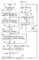
- FIGs. 6 and 7, the program which drives DAS 25 is entered at entry block 500 responsive to a craftsperson activating DAS 25 via terminal 30.
- the program proceeds to block 501 where it obtains the identities of the switches contained in the associated Central Office (CO) from LFACS 50.
- the program then proceeds to block 502 where it instructs each of those switches to begin maintaining a list of call processing activities involving their respective outside plant facilities. That is, a list of the telephone numbers associated with calls that are successfully forwarded to or originated from its outside plant.
- the program then proceeds to block 503 where it obtains from LFACS 50 the identity of each cable contained in the outside plant associated with each identified switch.
- the program proceeds to block 505 if it has obtained all such cable identities.
- the program creates a logical subplant for each identified switch in the manner described above and then proceeds to block 506, where it obtains from LFACS 50 the assignments for each loop pair of each cable forming a logical subplant.
- the program then proceeds to block 507 where it checks to see if it has completed the foregoing task for cable i and proceeds to block 508 if has done so. Otherwise, it returns to block 506.
- the program creates a status list for each identified cable and marks each assigned loop pair in the list as having a status of unknown.
- the program then obtains the OOS and ROH lists from each identified switch and then, at block 509, updates the status list for the associated cable using the OOS and ROH lists in the manner described above.
- the program requests the aforementioned call processing list from each switch n and then, at block 511, updates the status lists as was similarly done at block 509.
- the program proceeds to block 513 if it finds that it has completed such updating (for the present entry). Otherwise, it returns to block 508 to update the status of the loop pairs in the cables associated with next switch i.
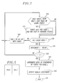
- the program exits via block 514 if it had been entered via block 600 as a subroutine call. Otherwise, it proceeds to block 515, where it respectively sets two variables i and j to a value of zero and identity of the first cable in the first logical subplant. It also sets a variable k to a particular value, e.g., a value derived from the average number of loop pairs in a cable.
- the program then proceeds to block 516 where it determines if cable j has only i loop pairs of known status (i.e., working or trouble) and proceeds to block 517 if it finds that to be the case. Otherwise, it proceeds to block 518.
- the program directs the ALIT facility to perform a test on one of the loop pairs having a status of unknown in cable j.
- the program then checks to see if it has completed processing all cables for the current value of i and proceeds to block 519 if that is the case. Otherwise, it proceeds to block 524.
- the program increments i and proceeds to block 520 where it checks to to see if the value of i exceeds the value of k.
- the program proceeds to block 521 where it calculates the level of confidence it has in the current status of the loop pairs that it has determined for cable j and then proceeds to block 522 to output the damage assessment to terminal 30.
- the program then exits via block 523.
- the program sets j to equal the identity of the next cable that needs to be processed.
- block 521 could be arranged so that if the confidence level for the damage assessment does not meet a predetermined value, then directed ALITs may be continued for that cable until the level of confidence in the damage assessment for that cable reaches a predetermined threshold. For example, the value of k may be increased so that additional ALITS may be performed on that cable by retuning to block 516.
- DAS 25 may be arranged so that it monitors the Common Channel Signaling (CCS) network (not shown) that is used by the switches in a network to transmit and receive messages relating to the processing of calls. These messages contain the telephone number of the originating and/or terminating line. That is, DAS 25 may be arranged so that it receives notification of successful originating or terminating interoffice calls by monitoring the CCS trunk signaling messages that switch 10 sends and receives over the CCS network.
- CCS Common Channel Signaling
- the number of per call messages that switch 10 sends to DAS 25 may be reduced if switch 10 is also arranged to generate a copy of line status table 125. As such, switch 10 need only notify DAS 25 of changes in the status of various telephone lines. As such, switch 10 may limit the number of times it notifies DAS 25 of a successful call completion over a particular telephone line to one. As a further example, once the inventive damage assessment arrangement has accumulated a sufficient number of samples of traffic status and ALITs to formulate a cable damage assessment within certain levels of confidence, then DAS 25 may suspend additional ALITs on that cable. This feature would allow DAS 25 to direct switch 10 to focus ALITs on other distribution cables.
Landscapes
- Engineering & Computer Science (AREA)
- Signal Processing (AREA)
- Monitoring And Testing Of Exchanges (AREA)
- Testing Resistance To Weather, Investigating Materials By Mechanical Methods (AREA)
Applications Claiming Priority (2)
| Application Number | Priority Date | Filing Date | Title |
|---|---|---|---|
| US55425 | 1993-04-29 | ||
| US08/055,425 US5450468A (en) | 1993-04-29 | 1993-04-29 | Method of rapidly assessing damage to outside loop plant |
Publications (2)
| Publication Number | Publication Date |
|---|---|
| EP0622937A2 true EP0622937A2 (fr) | 1994-11-02 |
| EP0622937A3 EP0622937A3 (fr) | 1995-06-14 |
Family
ID=21997709
Family Applications (1)
| Application Number | Title | Priority Date | Filing Date |
|---|---|---|---|
| EP94302582A Withdrawn EP0622937A3 (fr) | 1993-04-29 | 1994-04-13 | Procédé d'évaluation rapide du dommage à une bande extérieur. |
Country Status (4)
| Country | Link |
|---|---|
| US (1) | US5450468A (fr) |
| EP (1) | EP0622937A3 (fr) |
| JP (1) | JPH06334737A (fr) |
| CA (1) | CA2114154C (fr) |
Cited By (1)
| Publication number | Priority date | Publication date | Assignee | Title |
|---|---|---|---|---|
| WO1999007129A1 (fr) * | 1997-07-31 | 1999-02-11 | British Telecommunications Public Limited Company | Localisation d'une defaillance dans un reseau d'acces |
Families Citing this family (7)
| Publication number | Priority date | Publication date | Assignee | Title |
|---|---|---|---|---|
| US5799016A (en) * | 1996-01-11 | 1998-08-25 | U S West, Inc. | Network addressing scheme encoding communication channel information |
| US5764756A (en) * | 1996-01-11 | 1998-06-09 | U S West, Inc. | Networked telephony central offices |
| US5835566A (en) * | 1996-03-29 | 1998-11-10 | Telecom Technologies, Inc. | System and method for providing in-band and out-of-band testing of telecommunications network components |
| IL121501A (en) * | 1997-08-08 | 2003-04-10 | Icq Inc | Telephone-status notification system |
| US6101216A (en) | 1997-10-03 | 2000-08-08 | Rockwell International Corporation | Splitterless digital subscriber line communication system |
| US6445733B1 (en) | 1997-10-03 | 2002-09-03 | Conexant Systems, Inc. | Method of and apparatus for performing line characterization in a non-idle mode in a subscriber line communication system |
| US7065181B2 (en) * | 2002-12-03 | 2006-06-20 | Bellsouth Intellectual Property Corp. | System and method for improving the automated loop makeup process |
Family Cites Families (7)
| Publication number | Priority date | Publication date | Assignee | Title |
|---|---|---|---|---|
| US4479196A (en) * | 1982-11-15 | 1984-10-23 | At&T Bell Laboratories | Hyperedge entity-relationship data base systems |
| HU187198B (en) * | 1982-12-14 | 1985-11-28 | Bhg Hiradastech Vallalat | Circuit arrangemenet for the supervison of the telephon circuits |
| US4839917A (en) * | 1987-10-29 | 1989-06-13 | Oliver Stewart W | Universal line status monitoring and response system |
| US4864597A (en) * | 1988-02-17 | 1989-09-05 | Fore Don C | Cable pair tester |
| US5018189A (en) * | 1988-06-23 | 1991-05-21 | Canon Kabushiki Kaisha | Communication apparatus with telephone and data communication capability |
| US4937851A (en) * | 1988-07-20 | 1990-06-26 | Keptel, Inc. | Loop status verification system |
| FR2664153B1 (fr) * | 1990-07-06 | 1992-09-11 | Gen Electric Cgr | Systeme de radiodiagnostic pour examen angiographique avec dispositif automatique de suivi d'embole. |
-
1993
- 1993-04-29 US US08/055,425 patent/US5450468A/en not_active Expired - Fee Related
-
1994
- 1994-01-25 CA CA002114154A patent/CA2114154C/fr not_active Expired - Fee Related
- 1994-04-13 EP EP94302582A patent/EP0622937A3/fr not_active Withdrawn
- 1994-04-26 JP JP6109185A patent/JPH06334737A/ja active Pending
Cited By (2)
| Publication number | Priority date | Publication date | Assignee | Title |
|---|---|---|---|---|
| WO1999007129A1 (fr) * | 1997-07-31 | 1999-02-11 | British Telecommunications Public Limited Company | Localisation d'une defaillance dans un reseau d'acces |
| US6233312B1 (en) | 1997-07-31 | 2001-05-15 | British Telecommunications Public Limited Company | Inter-circuit line fault location in telecommunication networks |
Also Published As
| Publication number | Publication date |
|---|---|
| US5450468A (en) | 1995-09-12 |
| EP0622937A3 (fr) | 1995-06-14 |
| CA2114154A1 (fr) | 1994-10-21 |
| CA2114154C (fr) | 1997-12-02 |
| JPH06334737A (ja) | 1994-12-02 |
Similar Documents
| Publication | Publication Date | Title |
|---|---|---|
| CA1253241A (fr) | Service telephonique pour distributeurs d'appels automatiques | |
| EP0606353B1 (fr) | Gestion des encombrements dans des reseaux de telecommunication | |
| US5687212A (en) | System for reactively maintaining telephone network facilities in a public switched telephone network | |
| US5790634A (en) | Combination system for proactively and reactively maintaining telephone network facilities in a public switched telephone system | |
| US5953389A (en) | Combination system for provisioning and maintaining telephone network facilities in a public switched telephone network | |
| US4456788A (en) | Telecommunication trunk circuit reporter and advisor | |
| US5835572A (en) | Customized, billing controlled call bridging system | |
| US5715306A (en) | Automatic call distribution system with user definable logging and method therefor | |
| US5790633A (en) | System for proactively maintaining telephone network facilities in a public switched telephone network | |
| US5696809A (en) | Advanced intelligent network based computer architecture for concurrent delivery of voice and text data using failure management system | |
| US5488715A (en) | Process for integrated traffic data management and network surveillance in communications networks | |
| US5633922A (en) | Process and apparatus for restarting call routing in a telephone network | |
| US6208721B1 (en) | Method and apparatus for identifying telephone callers who have been unsuccessful in reaching a called destination | |
| US6636486B1 (en) | System, method and apparatus for monitoring and analyzing traffic data from manual reporting switches | |
| US7324634B2 (en) | Telecommunications systems | |
| US5450468A (en) | Method of rapidly assessing damage to outside loop plant | |
| US5923742A (en) | System and method for detecting mass addressing events | |
| CA1204488A (fr) | Methode et appareil de detection de defaillances dans les circuits de communication | |
| KR19980048788A (ko) | 통신망데이타를 이용한 접속실패율 및 가상호해제율 추출방법 | |
| US5815565A (en) | Service evaluation system and method for a telephonic switch | |
| US4260859A (en) | Method and apparatus for detecting transmission system failures in a communications network | |
| US7209553B2 (en) | Cutover method and device for telephone lines | |
| US4224477A (en) | Arrangement for translating telephone station equipment numbers into directory numbers | |
| KR0123254B1 (ko) | 서비스 교환기(ssp)에서 지능망 서비스 호를 시험하기 위한 응용 프로세스 시뮬레이션 방법 | |
| JP3291709B2 (ja) | インテリジェントネットワーク系サービスの加入者線及び局間共通線の信号モニタ方法 |
Legal Events
| Date | Code | Title | Description |
|---|---|---|---|
| PUAI | Public reference made under article 153(3) epc to a published international application that has entered the european phase |
Free format text: ORIGINAL CODE: 0009012 |
|
| AK | Designated contracting states |
Kind code of ref document: A2 Designated state(s): DE GB |
|
| PUAL | Search report despatched |
Free format text: ORIGINAL CODE: 0009013 |
|
| AK | Designated contracting states |
Kind code of ref document: A3 Designated state(s): DE GB |
|
| 17P | Request for examination filed |
Effective date: 19951129 |
|
| STAA | Information on the status of an ep patent application or granted ep patent |
Free format text: STATUS: THE APPLICATION HAS BEEN WITHDRAWN |
|
| 18W | Application withdrawn |
Withdrawal date: 19981030 |