EP0622977B1 - Dimmer für eine Entladungslampe - Google Patents
Dimmer für eine Entladungslampe Download PDFInfo
- Publication number
- EP0622977B1 EP0622977B1 EP93403034A EP93403034A EP0622977B1 EP 0622977 B1 EP0622977 B1 EP 0622977B1 EP 93403034 A EP93403034 A EP 93403034A EP 93403034 A EP93403034 A EP 93403034A EP 0622977 B1 EP0622977 B1 EP 0622977B1
- Authority
- EP
- European Patent Office
- Prior art keywords
- dimming
- lamp
- mode
- power
- terminals
- Prior art date
- Legal status (The legal status is an assumption and is not a legal conclusion. Google has not performed a legal analysis and makes no representation as to the accuracy of the status listed.)
- Expired - Lifetime
Links
- 230000002238 attenuated effect Effects 0.000 claims abstract 7
- 230000001143 conditioned effect Effects 0.000 claims abstract 2
- 239000007858 starting material Substances 0.000 claims description 32
- 230000007704 transition Effects 0.000 claims description 6
- 239000003990 capacitor Substances 0.000 description 13
- DGAQECJNVWCQMB-PUAWFVPOSA-M Ilexoside XXIX Chemical compound C[C@@H]1CC[C@@]2(CC[C@@]3(C(=CC[C@H]4[C@]3(CC[C@@H]5[C@@]4(CC[C@@H](C5(C)C)OS(=O)(=O)[O-])C)C)[C@@H]2[C@]1(C)O)C)C(=O)O[C@H]6[C@@H]([C@H]([C@@H]([C@H](O6)CO)O)O)O.[Na+] DGAQECJNVWCQMB-PUAWFVPOSA-M 0.000 description 3
- 230000000694 effects Effects 0.000 description 3
- QSHDDOUJBYECFT-UHFFFAOYSA-N mercury Chemical compound [Hg] QSHDDOUJBYECFT-UHFFFAOYSA-N 0.000 description 3
- 229910052753 mercury Inorganic materials 0.000 description 3
- 238000009420 retrofitting Methods 0.000 description 3
- 229910052708 sodium Inorganic materials 0.000 description 3
- 239000011734 sodium Substances 0.000 description 3
- 230000005540 biological transmission Effects 0.000 description 2
- 230000001934 delay Effects 0.000 description 2
- 229910052736 halogen Inorganic materials 0.000 description 2
- 150000002367 halogens Chemical class 0.000 description 2
- 238000005286 illumination Methods 0.000 description 2
- 238000000034 method Methods 0.000 description 2
- 230000000903 blocking effect Effects 0.000 description 1
- 230000008878 coupling Effects 0.000 description 1
- 238000010168 coupling process Methods 0.000 description 1
- 238000005859 coupling reaction Methods 0.000 description 1
- 230000007423 decrease Effects 0.000 description 1
- 230000003247 decreasing effect Effects 0.000 description 1
- 230000008021 deposition Effects 0.000 description 1
- 238000010586 diagram Methods 0.000 description 1
- 238000010438 heat treatment Methods 0.000 description 1
- 238000010348 incorporation Methods 0.000 description 1
- 230000006698 induction Effects 0.000 description 1
- 238000009434 installation Methods 0.000 description 1
- 229910052751 metal Inorganic materials 0.000 description 1
- 239000002184 metal Substances 0.000 description 1
- 230000002035 prolonged effect Effects 0.000 description 1
Images



Classifications
-
- H—ELECTRICITY
- H05—ELECTRIC TECHNIQUES NOT OTHERWISE PROVIDED FOR
- H05B—ELECTRIC HEATING; ELECTRIC LIGHT SOURCES NOT OTHERWISE PROVIDED FOR; CIRCUIT ARRANGEMENTS FOR ELECTRIC LIGHT SOURCES, IN GENERAL
- H05B41/00—Circuit arrangements or apparatus for igniting or operating discharge lamps
- H05B41/14—Circuit arrangements
- H05B41/36—Controlling
- H05B41/38—Controlling the intensity of light
- H05B41/39—Controlling the intensity of light continuously
- H05B41/392—Controlling the intensity of light continuously using semiconductor devices, e.g. thyristor
- H05B41/3921—Controlling the intensity of light continuously using semiconductor devices, e.g. thyristor with possibility of light intensity variations
- H05B41/3924—Controlling the intensity of light continuously using semiconductor devices, e.g. thyristor with possibility of light intensity variations by phase control, e.g. using a triac
-
- H—ELECTRICITY
- H05—ELECTRIC TECHNIQUES NOT OTHERWISE PROVIDED FOR
- H05B—ELECTRIC HEATING; ELECTRIC LIGHT SOURCES NOT OTHERWISE PROVIDED FOR; CIRCUIT ARRANGEMENTS FOR ELECTRIC LIGHT SOURCES, IN GENERAL
- H05B41/00—Circuit arrangements or apparatus for igniting or operating discharge lamps
- H05B41/14—Circuit arrangements
- H05B41/16—Circuit arrangements in which the lamp is fed by DC or by low-frequency AC, e.g. by 50 cycles/sec AC, or with network frequencies
- H05B41/18—Circuit arrangements in which the lamp is fed by DC or by low-frequency AC, e.g. by 50 cycles/sec AC, or with network frequencies having a starting switch
-
- Y—GENERAL TAGGING OF NEW TECHNOLOGICAL DEVELOPMENTS; GENERAL TAGGING OF CROSS-SECTIONAL TECHNOLOGIES SPANNING OVER SEVERAL SECTIONS OF THE IPC; TECHNICAL SUBJECTS COVERED BY FORMER USPC CROSS-REFERENCE ART COLLECTIONS [XRACs] AND DIGESTS
- Y10—TECHNICAL SUBJECTS COVERED BY FORMER USPC
- Y10S—TECHNICAL SUBJECTS COVERED BY FORMER USPC CROSS-REFERENCE ART COLLECTIONS [XRACs] AND DIGESTS
- Y10S315/00—Electric lamp and discharge devices: systems
- Y10S315/04—Dimming circuit for fluorescent lamps
Definitions
- the present invention concerns an apparatus for dimming light of gas discharge lamps such as fluorescent lamps.
- dimmers operate on a basis of chopping the power, meaning, transmitting only through part of the time of the alternating current cycle, shutting it off during the rest. The extent of the transmission time in each cycle determines the amount of dimming.
- Dimmers typically consist of a user-controlled potentiometer operating in conjunction with a triac or an SCR.
- dimmers particularly such as available in domestic use, are capable of dimming a light of lamps such as incandescent type lamps or halogen lamps.
- standard dimmers are unsuitable for dimming light of gas discharge lamps such as fluorescent lamps, high or low pressure mercury or sodium lamps, etc.
- the light of a gas discharge lamp either flickers or extinguishes altogether.
- Gas discharge lamps have a gas filled space or tube with two spaced electrodes (heated or not). When heated, an electrode is a two terminal filament. One terminal of each of the two electrode is connected to a pole of the AC power source and the other terminals of the two electrodes are typically linked together by the intermediary of a so-called "starter".
- a choke/ballast is installed between one of the electrodes and the respective pole of the power source and sometimes a capacitor is installed in series or parallel to the lamp to correct the power factor (cos-fi) and/or limit the current.
- an initial high voltage that can supply enough electric charge is required.
- an appropriate voltage is to be generated to cause such a discharge.
- the electric current flows at first, through the choke, one filament electrode of the starter and the second filament electrode of the lamp. After an initial short period of time, the filaments are hot and the starter disconnects, with the result of abrupt current change through the choke which, in turn, causes a very high voltage across the fluorescent lamp, above the threshold required for ignition of the discharge. Following initial ignition, the gas discharge lamp continues to emit light while the choke limits the currents, as long as it is supplied with electric power a minimal value.
- dimmers for gas discharge lamps such as fluorescent lamps.
- the standard choke is replaced by an electronic choke which is an oscillator that generates an alternating electric power at high frequency, of the order of 25-100 KHz.
- dimming is achieved by modulating the oscillator and whilst effective dimming is achieved, such dimmer entail significant drawbacks in that they are somewhat inefficient and expensive and that retrofitting a light circuit to operate them requires relatively expensive hardware.
- dimmers involve the use of a heating transformer intended to preheat the filaments in order to reduce the threshold voltage required to initiate the gas discharge.
- the drawback here is similar to that of the Hi-Fi dimmers in that it requires a very expensive hardware. Furthermore, such dimmers are inappropriate for various kinds of gas discharge lamps that do not depend on preheating of their electrodes such as various types of high pressure gas discharge lamps and high or low pressure mercury or sodium lamps and others.
- GB-2 136 226 discloses a load switching arrangement for gas discharge lamp circuit.
- WO 90/02475 discloses a time delay initialization circuit.
- the present invention is based on the surprising finding that unlike prior belief in this field, effective dimming of a gas discharge lamp may be achieved by the use of circuitry, which can be installed into a standard circuitry without a need for cumbersome and expensive retrofitting of the circuitry.
- full power mode is to be interpreted in the context of the description and the appended claims as essentially “full power mode”. Thus, for example, 90% of the maximal power is considered in some cases as full power mode.
- the dimming means controls light in a plurality of lamps
- the transition from a non-dimmed, i.e. maximal power state, into a state in which the light has been dimmed should be gradual.
- the duration of the transition period between maximal power state and a dimmed state depends on various factors including the number of lamps, the type of lamps used and other factors. The correlation between these factors and the aforesaid time duration has to be determined in each particular case.
- disconnecting means that the current flow through the starter drops to essentially zero.
- the standard bimetal starters can resume contact if the voltage decreases beyond a certain value and thus by the use of such starters, in a dimming mode of operation, there is risk of light flickering or a total distinguishing thereof;
- a dimming assembly may incorporate characterizing features of both of the above embodiments.
- a full power and a gradual transition to dimming mode may be implemented in said program.
- time delays t 1 and t 2 should be adjusted in accordance with the particular application. Typically, the extent of the desired dimming, the number and type of lamps used and various other factors affect the values of t 1 and t 2 . By way of example, in case of a single lamp and a desired dimming extent of 50%, t 1 may be selected to be 50 secs. and t 2 to be 200 secs. It should be noted that for a given lighting system t 1 and t 2 may be automatically adjusted for a given desired dimming extent.
- the dimming controller in the dimmer assembly of the invention may be any suitable means such as those operated on the basis of signal chopping, e.g., using triacs or SCRs, using an impedance control system, etc.
- the dimming is achieved by blocking the electric current from going through the lamps during part of each half of the Ac cycle, following the "zero crossing", and letting it flow during the rest of the half cycle. This chopping repeats itself each half cycle.
- a triac or twin SCR's together with a programmable controller and timer, form collectively the dimming controller of the invention.
- the triac if needed, is protected by a passive "body guard".
- the Triac body guard is typically a saturable inductor or a collapsible resistor that restricts the current during switching of the signal chopping means but has essentially no impedance once the current exceeds some critical value. By so doing, the body guard greatly diminishes the energy deposition in the signal chopping means during the switching time, thereby protecting it from being damaged.
- the controller repeats the foregoing sequence of operations whereby the lamps are automatically restarted and brought into the desired dimmed condition.
- the present invention further provides a lighting system comprising :
- Retrofitting existing lighting systems to a system in accordance with the invention is a very simple and rapid procedure and involves only changing of the standard light switch to a dimmer assembly of the invention and setting the potentiometers and possibly, for fluorescent lamps that have filament-electrodes and use a bimetallic starter, also replacing the starter of each lamp with an electronic starter; There is no need for any additional change in the circuitry, unlike most other dimming systems available to date.
- dimming in accordance with the invention is characterized by an increase in the efficiency, that is the "light to power" ratio. It has been found that dimming in accordance with the invention is efficient in terms of consumption of energy.
- the controller of the present invention can be realized by utilizing digital components, analog components or a combination thereof.
- the controller consists exclusively of hardware components.
- the time delay t 1 of the full power is determined by an RC circuit and its setting is made with a potentiometer.
- the gradual period t 2 is controlled by another RC circuit and is set by a second potentiometer.
- the level of dimming is set by a third potentiometer.
- the operation of the dimming controller may be realized by a suitably programmed controller.
- Fig. 1 showing a light system of the invention.
- the system of this embodiment includes a plurality (n) identical fluorescent tubes of which only two are shown, those designated F1 and Fn. These fluorescent tubes may for example be standard, 40 W " day light " type of the kind manufactured by OSRAMTM.
- Each of the tubes includes two spaced electrode filaments 5 and 6.
- One terminal 7 of filament 5 is electrically coupled to a proximal terminal of choke ballast 8 , being for example of the kind manufactured by SHWABBE.
- Terminal 9 of electrode filament 6 is connected to one terminal of an AC (alternating current) power source, e.g. 220 volts, 50 Hz.
- the other terminals 11 and 12 of electrode filaments 5 and 6 are electrically coupled to respective terminals 13 and 14 of starter 15.
- Dimmer assembly 17 comprises an on/off switch 18 (which may be coupled to a potentiometer 25 but which is shown herein for the sake of clarity as a separate component), dimming controller 19 and a bypass means 20.
- Dimming controller 19 has an input terminal 21 and an output terminal 22. Linking the two terminals 21 and 22 is a triac component 23 which should be selected so that its maximal power output is compatible with the power requirements of the plurality of fluorescent tubes F1 to Fn.
- the power transmission through triac 23 is controlled by gate 24.
- Potentiometer 25 (which as pointed out above is coupled to switch 18 ) is linked to a user controlled dial whereby the user selects the required dimming degree. Potentiometer 25 operates in a combination with capacitor 26, resistor 27 and diac 28, in a manner which is no doubt clear to the artisan to modulate the voltage at gate 24 whereby the electric power through triac 23 is chopped depending on the selected position of potentiometer 25.
- bypass means 20 may be implemented by triac 23 which when set to full conductance, by suitable modulation of gate 24, facilitates the bypass mode and alternatively when set to partial conductance facilitates the dimmed mode.
- the dimming means also comprises an optional histeresis compensating circuitry generally indicated 30 which comprises four diodes 31-34 and resistors 35 and 36.
- the function of the histeresis compensation unit is to render the dimmer operation symmetrical in the sense that the current attenuation upon increase in the degree of attenuation will be the same at each point as where the dimming degree is decreased.
- the histeresis compensating means essentially confers increased users' convenience in that it neutralizes the known histeresis effect which is a common drawback shared by many dimming units.
- the dimmer assembly 17 comprises also a gradual dimming means 40, adapted to provide for a gradual entry into a dimmed mode, and compensator resistor means 50 the function of which will be elaborated further below.
- bypass means 20 short circuits terminals 21 and 22 and consequently the entire electric power flows directly at full intensity to the plurality of fluorescent light bulbs F1 to Fn through their associated chokes 8 .
- the bypass means switches from the full power mode, to the dimming mode in which the direct connection between terminals 21 and 22 is disconnected and consequently the power between these two terminals is now routed entirely through dimming controller 19.
- the extent of power output at terminal 22 is determined by means of potentiometer 25 as explained above.
- the system can operate with a plurality of fluorescent lamps, unlike many dimmers that are available today. However, when plurality of fluorescent lamps are utilized the gradual dimming means 40 should be activated.
- Starter 15 consists of an SCR 60 linked to terminal 11 through the intermediary of diode 61 and to terminal 12 through the intermediary of diodes 62-65.
- the circuitry further comprises an SCR 67, additional diodes 71-73, zener diode 74, a plurality of resistors 77-82 and three capacitors 83, 84 and 85.
- the sub-circuit consisting of resistors 77, 78, capacitors 83 and 84, diode 71, and zener diode 74 which is linked to gate 90 SCR 60, brings SCR 60 into a conduction mode in which current flows between terminals 11 and 12.
- SCR 67 enters into conduction mode whereby SCR 60 is disconnected and consequently the electrical contact between terminals 11 and 12 is disconnected. This disconnection then facilitates the ignition of the gas discharge effect as already discussed above.
- SCR 67 As long as potential is applied to terminal 11, conductive conditions are maintained in SCR 67 and consequently SCR 60 is constantly disconnected essentially independent of the voltage at terminal 11.
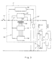
- Fig. 3 showing a system in accordance with another embodiment of the invention.
- the operation of dimming assembly 101 in accordance with this embodiment is essentially similar to that in the embodiment of Fig. 1, the two differing from one another by the dimmer controller, generally designated 102, which in the embodiment of Fig. 4 operates on the basis of impedance control. All other features of the system are essentially identical to those of Fig. 1 and were given the same reference numerals with prime indications.
- Dimmer means 102 comprise a primary coil 105 and a secondary coil 106.
- the dimming effect is achieved by changing the induction ratio between the primary and secondary coils 105, 106, respectively, which, in practice is obtained by selecting the active taps of coil 106.
- the taps are associated to user controllable dimming control means 107, whereby the user is capable of selecting the desired dimming extent.
- the number of taps determines the number of dimming levels. In Fig. 3, three taps are shown although it will be appreciated by the artisan that this is only an example and the secondary coil may have any other number of taps.
- Auxiliary unit 108 has the same function as auxiliary unit 40 in Fig. 1.
- FIG. 4 showing the circuitry of the bypass and the gradual dimming means (components 20 and 40 ). It should be noted, however, that in Fig. 4 both bypass means 20 and gradual dimming means 40 are incorporated together into one circuitry.
- Potentiometer 200, 201, amplifiers 202, 203, diodes 207, 220, resistors 210, 213 and capacitor 215 constitute collectively the bypass means.
- the incorporation of the circuitry shown in Fig. 4 within the dimmer controller, such as that shown in Fig. 1, is not shown in the drawings as being straightforward to those versed in the art.
- potentiometer 200 (which is similar in its function to potentiometer 25 of Fig. 1) is set to the desired dimming extent which should exceed a minimal threshold defined by reference voltage fed to the negative input of amplifier 202.
- the setting of potentiometer 200 results in generation of saturation voltage at the output of amplifier 202.
- the latter imposes a reference voltage, e.g. about 7.5V, at the positive input of amplifier 203 which in turn forces positive saturation at the output of amplifier 203 thereby facilitating the so-called full power mode.
- the negative input of amplifier 203 will exceed the 7.5V reference voltage after the capacitor 215 is charged to the suitable threshold so as to force an equivalent voltage (e.g. about 7.5V) at the negative input of amplifier 203 .
- the charging rate of the capacitor 215 is contingent on the time delay defined by the potentiometer 201 and capacitor 215, and may, for example, be about 3 minutes. Once the negative input voltage of amplifier 203 exceeds the reference voltage, the output of latter drops to 0 due to diode 207.
- the input power is routed via triac 23 (refer to Fig. 1) thus facilitating the so-called dimmed mode.
- the control signal to the gate of the triac 23 is fed via the potentiometer 200 and diode 220.
- the circuit may be easily modified, as is well known to the artisan, so that the position selected by the user in potentiometer 200 controls the time delay which in Fig. 4 is determined merely by the combination of potentiometer 201 and capacitor 215.
- the gradual dimming is achieved by potentiometers 200, 222, diodes 207, 220, amplifier 203 and capacitor 221.
- the voltage potential of junction 223 remains in positive saturation due to capacitor 221 which was changed during the full power mode period thus maintaining initial full power in spite of the power drop at the output of amplifier 203.
- the gradual attenuation terminates as the voltage potential at junction 223 drops to the level determined by the potentiometer 200 (via diode 220 ) entering full dimmed mode.
- an impedance control dimmer assembly similar as in the embodiment in Fig. 3 was found to be advantageous over use of the wave-chopping based system as in the embodiment of Fig. 1.
- the system of the invention is applicable for a large number of gas discharge lamps. Hitherto available dimmer systems have failed to work with various types of fluorescent lamps which are effectively dimmed by the use of the dimmer assembly of the invention.
- the assembly of the present invention works very effectively for dimming light of a fluorescent lamp of the kind having a 26 mm diameter, 36 W power employing a so-called rapid start starter.
- the assembly is also applicable for various other lamp types such as, for example, 18 W or 58 W lamps of the same diameter.
- Compensating resistors 50 in Fig. 1 and 50' in Fig. 3 are connected in parallel to bypass means 20 and 20', respectively and a compensating resistor 51 is connected between the output terminal 22 line 52.
- a compensating resistor 51 is connected between the output terminal 22 line 52.
- a 5 W, 1 k ⁇ or 2.5 k ⁇ compensating resistor is applicable in the case of the abovementioned fluorescent lamp.
- the determination whether to employ single or both of the compensating resistors and their values is made empirically in each case. It should be noted that the use of such compensating resistor may be utilized also in systems in which gradual dimming controller or bypass means are not required.
- the system of the invention is also applicable for dimming light of various compact fluorescent lamps, having integral built-in starters such as those manufactured by OSRAMTM or PHILLIPSTM.
- integral built-in starters such as those manufactured by OSRAMTM or PHILLIPSTM.
- a bi-metal starter may be utilized, but this has to be replaced with an electronic starter similar to that shown in Fig. 3, where the fluorescent lamps are of a higher power type.
- an additional circuitry may be incorporated to the assembly of the invention, which, in case of an instantaneous power loss delays the resumption of power to the system for a certain time interval, e.g. for 30 secs.
- the dimmer assembly of the invention may be used in light system employing sodium or mercury lamps.
Landscapes
- Engineering & Computer Science (AREA)
- Power Engineering (AREA)
- Discharge-Lamp Control Circuits And Pulse- Feed Circuits (AREA)
- Circuit Arrangements For Discharge Lamps (AREA)
- Circuit Arrangement For Electric Light Sources In General (AREA)
- Arrangement Of Elements, Cooling, Sealing, Or The Like Of Lighting Devices (AREA)
Claims (11)
- Dimmer- bzw. Helligkeitsregleraufbau zum Steuern der Lichtintensität einer Gasentladungslampe (1, 2) mit:einem dimmenden bzw. helligkeitsregelnden Steuergerät (17, 17') mit einem Eingangsanschluß (21, 21'), der mit einem Pol einer Wechselstromquelle verbunden werden kann, und mit einem Ausgangsanschluß (22, 22'), der mit der Leitung verbunden werden kann, die zu einer der beiden Fadenelektroden (5, 5') der Lampe führt, wobei das helligkeitsregelnde Steuergerät (17, 17') dafür ausgelegt ist, an seinem Ausgangsanschluß eine gedämpfte und festgesetzte Leistung zu liefern;wobei das helligkeitsregelnde Steuergerät (17, 17') bei Versorgen des Eingangsanschlusses (21, 21') mit dem Strom dafür ausgelegt ist, in einem ersten Modus, der einen Modus mit voller Leistung bildet, für eine Zeitperiode t1 zu arbeiten, während der die Verbindung zwischen seinen beiden Anschlüssen (21, 21'; 22, 22') den vollen Wirkleitwert aufweist, der eine volle Lichtintensität der Entladungslampe bewirkt, und ferner dafür ausgelegt ist, nach t1 in einen zweiten Modus einzutreten, der einen Dimm- bzw. Helligkeitsregelmodus bildet, während dem die Verbindung zwischen seinen beiden Anschlüssen einen partiellen Wirkleitwert aufweist, der eine gedämpfte Intensität der Entladungslampe bewirkt;
wobei die Zeit t1 ausreicht, ein wirksames Dimmen bzw. Helligkeitsregeln in dem Helligkeitsregelmodus zu erleichtern;
gekennzeichnet durch:einen elektronischen Starter (15, 15') mit zwei Starteranschlüssen (13, 13', 14, 14'), die jeweils mit je einer der Fadenelektroden (5, 5', 6, 6') der Lampe verbunden werden können, der, wenn er zu Anfang erregt wird, eine elektrische Verbindungsfähigkeit zwischen den Elektroden ermöglicht und nach einer vorbestimmten Zeitverzögerung die elektrische Verbindungsfähigkeit sperrt, wodurch die alleinige Verbindung zwischen den beiden Starteranschlüssen (13, 13', 14, 14') dann durch das Entladungsgas im Innern der Lampe besteht und wodurch eine Trennfähigkeit im wesentlichen unabhängig von der an die Lampe angelegten Spannung aufrechterhalten wird. - Helligkeitsregleraufbau nach Anspruch 1, in dem das helligkeitsregelnde Steuergerät (17, 17') ferner imstande ist, für eine Übergangsperiode t2 zwischen dem ersten Modus mit voller Leistung und dem zweiten Helligkeitsregelmodus nach und nach umzuschalten.
- Helligkeitsregleraufbau zum Steuern einer Lichtintensität einer Gasentladungslampe mit:gekennzeichnet durch:einem helligkeitsregelnden Steuergerät (17, 17') mit einem Eingangsanschluß (21, 21'), der mit einem Pol einer Wechselstromquelle verbunden werden kann, und mit einem Ausgangsanschluß (22, 22'), der mit der Leitung verbunden werden kann, die zu einer der beiden Fadenelektroden (5, 5') der Lampe führt, wobei das helligkeitsregelnde Steuergerät (17, 17') dafür ausgelegt ist, an seinem Ausgangsanschluß eine gedämpfte Leistung bereitzustellen;das helligkeitsregelnde Steuergerät (17, 17') bei Versorgen des Eingangsanschlusses mit dem Strom dafür ausgelegt ist, für eine Übergangszeitperiode t2 von einem ersten Modus, der einen Modus mit voller Leistung bildet, nach und nach in einen zweiten Modus zu schalten, der einen Helligkeitsregelmodus bildet, in dem die Verbindung zwischen seinen beiden Anschlüssen (21, 21'; 22, 22') einen partiellen Wirkleitwert aufweist, der eine gedämpfte Intensität der Entladungslampe bewirkt;wobei die Übergangszeit t2 ausreicht, um ein wirksames Dimmen bzw. Helligkeitsregeln zu erleichtern;einen elektronischen Starter (15, 15') mit zwei Starteranschlüssen (13, 13', 14, 14'), die jeweils mit je einer der Fadenelektroden (5, 5', 6, 6') der Lampe verbunden werden können, der, wenn er zu Anfang erregt wird, eine elektrische Verbindungsfähigkeit zwischen den Elektroden ermöglicht und nach einer vorbestimmten Zeitverzögerung die elektrische Verbindungsfähigkeit sperrt, wodurch die alleinige Verbindung zwischen den beiden Starteranschlüssen (13, 13', 14, 14') dann durch das Entladungsgas im Innern der Lampe besteht und wodurch die Trennfähigkeit im wesentlichen unabhängig von der an die Lampe angelegten Spannung aufrechterhalten wird.
- Helligkeitsregleraufbau nach einem der Ansprüche 1 bis 3 ferner mit einer Kompensator-Widerstandseinrichtung (50, 50').
- Helligkeitsregleraufbau nach einem der Ansprüche 1 bis 4, mit einer Signal zerhackenden Einrichtung (23, 105).
- Helligkeitsregleraufbau nach Anspruch 5, in dem die ein Signal zerhackende Einrichtung eine Zweirichtungsthyristortriode bzw. ein Triac (23) ist.
- Helligkeitsregleraufbau nach einem der Ansprüche 1 bis 6, mit einem Impedanzsteuersystem (105).
- Helligkeitsregleraufbau nach einem der Ansprüche 1 bis 7, ferner mit einem Körperschutz (55, 56).
- Helligkeitsregleraufbau nach einem der Ansprüche 1 bis 8, ferner mit einer Leistungssteuereinheit.
- Beleuchtungssystem mit:einer oder mehr Gasentladungslampen (1, 2), die jeweils zwei beabstandete Fadenelektroden (5, 5', 6, 6') aufweisen, wobei jede Elektrode mit einem jeweiligen Pol einer elektrischen Energiequelle verbunden ist;jeder Lampe zugeordneten Drosseleinrichtungen und Startereinrichtungen (8, 8', 15, 15'); undeinem Dimmer- bzw. Helligkeitsregler-Steuergerät (17, 17') auf einer elektrischen Leitung, die eine der Fadenelektroden (5, 5') jeder Lampe mit dem einen Pol der Energiequelle verbindet;wobei das Helligkeitsregler-Steuergerät und die Startereinrichtung wie in einem der Ansprüche 1 bis 9 definiert vorliegen.
- Helligkeitsregleraufbau nach einem der Ansprüche 1 bis 9, ferner mit einer Leistungssteuereinheit, um die Schaltungsanordnung des Aufbaus ungeachtet einer etwaigen Störung in der tatsächlichen Energieversorgung mit einer stabilisierten Eingangsleistung zu versorgen.
Applications Claiming Priority (2)
| Application Number | Priority Date | Filing Date | Title |
|---|---|---|---|
| IL10556493A IL105564A (en) | 1993-04-30 | 1993-04-30 | Dimmer for discharge bulb |
| IL10556493 | 1993-04-30 |
Publications (3)
| Publication Number | Publication Date |
|---|---|
| EP0622977A2 EP0622977A2 (de) | 1994-11-02 |
| EP0622977A3 EP0622977A3 (de) | 1994-11-17 |
| EP0622977B1 true EP0622977B1 (de) | 1999-03-24 |
Family
ID=11064794
Family Applications (1)
| Application Number | Title | Priority Date | Filing Date |
|---|---|---|---|
| EP93403034A Expired - Lifetime EP0622977B1 (de) | 1993-04-30 | 1993-12-15 | Dimmer für eine Entladungslampe |
Country Status (10)
| Country | Link |
|---|---|
| US (1) | US5471116A (de) |
| EP (1) | EP0622977B1 (de) |
| JP (1) | JPH076621A (de) |
| CN (1) | CN1122098A (de) |
| AT (1) | ATE178183T1 (de) |
| AU (1) | AU677039B2 (de) |
| BR (1) | BR9401633A (de) |
| CA (1) | CA2121652A1 (de) |
| DE (1) | DE69324131T2 (de) |
| IL (1) | IL105564A (de) |
Families Citing this family (10)
| Publication number | Priority date | Publication date | Assignee | Title |
|---|---|---|---|---|
| US6034488A (en) * | 1996-06-04 | 2000-03-07 | Lighting Control, Inc. | Electronic ballast for fluorescent lighting system including a voltage monitoring circuit |
| CN1192689C (zh) * | 1998-10-01 | 2005-03-09 | 未来新发展有限公司 | 用于荧光管灯节能工作的电路配置 |
| US6316923B1 (en) * | 1999-01-14 | 2001-11-13 | Franco Poletti | Power control circuits for luminaires |
| EP1449410A1 (de) * | 2001-11-12 | 2004-08-25 | Koninklijke Philips Electronics N.V. | Schaltungsanordnung |
| DE10205552B4 (de) * | 2002-02-11 | 2017-02-09 | Ralf Kleinodt | Schaltungsanordnung und Ansteuerverfahren zur energieoptimalen Helligkeitssteuerung von Gasentladungslampen |
| DE102004025774A1 (de) * | 2004-05-26 | 2005-12-22 | Patent-Treuhand-Gesellschaft für elektrische Glühlampen mbH | Vorschaltgerät für Entladungslampe mit Dauerbetriebs-Regelschaltung |
| CN1719963A (zh) * | 2004-07-08 | 2006-01-11 | 皇家飞利浦电子股份有限公司 | 一种调光装置 |
| US7928663B1 (en) * | 2008-02-26 | 2011-04-19 | Crestron Electronics Inc. | Lighting dimmer adaptable to four wiring configurations |
| FR2934455B1 (fr) * | 2008-07-25 | 2010-08-27 | Citylone | Dispositif de modulation de l'alimentation d'une ampoule a decharge |
| DE102011100002B4 (de) * | 2011-04-29 | 2023-01-05 | Tridonic Gmbh & Co Kg | Vorrichtung zur Steuerung eines Beleuchtungsgeräts |
Citations (1)
| Publication number | Priority date | Publication date | Assignee | Title |
|---|---|---|---|---|
| EP0261389A1 (de) * | 1986-08-21 | 1988-03-30 | Honeywell Inc. | Wechselstromversorgungssteuerung, insbesondere für die Regulierung von Leuchtstofflampenlicht |
Family Cites Families (7)
| Publication number | Priority date | Publication date | Assignee | Title |
|---|---|---|---|---|
| DE3232592C1 (de) * | 1982-09-02 | 1984-03-22 | Harald 6000 Frankfurt Lück | Schaltungsanordnung zur Verminderung der Leistungsaufnahme einer Leuchtstofflampe |
| US4558262A (en) * | 1983-03-09 | 1985-12-10 | Lutron Electronics Co., Inc. | Load switching arrangement for gas discharge lamp circuit |
| US4876498A (en) * | 1986-03-13 | 1989-10-24 | Lutron Electronics Co. Inc. | Two wire low voltage dimmer |
| US4950963A (en) * | 1988-05-05 | 1990-08-21 | Sievers Richard L | Automatic light dimmer for gas discharge lamps |
| US4937504A (en) * | 1988-08-31 | 1990-06-26 | Honeywell Inc. | Time delay initialization circuit |
| KR910700598A (ko) * | 1989-02-10 | 1991-03-15 | 에타 인더스트리스, 인코포레이티드 | 가스방전램프를 구동 및 제어하기 위한 회로와 그 방법 |
| DE69029301T2 (de) * | 1989-03-27 | 1997-04-10 | Toshiba Lighting & Technology | Anzündanordnung für eine entladungslampe |
-
1993
- 1993-04-30 IL IL10556493A patent/IL105564A/en not_active IP Right Cessation
- 1993-12-13 US US08/166,501 patent/US5471116A/en not_active Expired - Fee Related
- 1993-12-15 EP EP93403034A patent/EP0622977B1/de not_active Expired - Lifetime
- 1993-12-15 DE DE69324131T patent/DE69324131T2/de not_active Expired - Fee Related
- 1993-12-15 AT AT93403034T patent/ATE178183T1/de active
-
1994
- 1994-04-19 CA CA002121652A patent/CA2121652A1/en not_active Abandoned
- 1994-04-21 AU AU60607/94A patent/AU677039B2/en not_active Withdrawn - After Issue
- 1994-04-27 JP JP6110157A patent/JPH076621A/ja active Pending
- 1994-04-28 BR BR9401633A patent/BR9401633A/pt not_active Application Discontinuation
- 1994-04-29 CN CN94104999A patent/CN1122098A/zh active Pending
Patent Citations (1)
| Publication number | Priority date | Publication date | Assignee | Title |
|---|---|---|---|---|
| EP0261389A1 (de) * | 1986-08-21 | 1988-03-30 | Honeywell Inc. | Wechselstromversorgungssteuerung, insbesondere für die Regulierung von Leuchtstofflampenlicht |
Also Published As
| Publication number | Publication date |
|---|---|
| IL105564A0 (en) | 1993-08-18 |
| US5471116A (en) | 1995-11-28 |
| EP0622977A3 (de) | 1994-11-17 |
| EP0622977A2 (de) | 1994-11-02 |
| DE69324131D1 (de) | 1999-04-29 |
| CA2121652A1 (en) | 1994-10-31 |
| ATE178183T1 (de) | 1999-04-15 |
| AU677039B2 (en) | 1997-04-10 |
| IL105564A (en) | 1996-06-18 |
| AU6060794A (en) | 1994-11-03 |
| JPH076621A (ja) | 1995-01-10 |
| CN1122098A (zh) | 1996-05-08 |
| BR9401633A (pt) | 1994-11-01 |
| DE69324131T2 (de) | 1999-10-28 |
Similar Documents
| Publication | Publication Date | Title |
|---|---|---|
| US7868561B2 (en) | Two-wire dimmer circuit for a screw-in compact fluorescent lamp | |
| US5504398A (en) | Dimming controller for a fluorescent lamp | |
| EP1013153B1 (de) | Verfahren zum vermeiden des irrtümlichen betriebs eines leuchtstofflampenvorschaltgerätes | |
| US6452343B2 (en) | Ballast circuit | |
| US4016451A (en) | High pressure discharge lamp dimming circuit utilizing variable duty-cycle photocoupler | |
| US5471116A (en) | General assembly for controlling light intensity of a gas discharge lamp | |
| US6707263B1 (en) | High-intensity discharge lamp ballast with live relamping feature | |
| US5955847A (en) | Method for dimming a fluorescent lamp | |
| US5422547A (en) | Fluorescent lamp control circuit with dimmer | |
| US5729097A (en) | Method and device for controlling electric discharge lamps with electronic fluorescent lamp ballasts | |
| EP0053896A1 (de) | Helligkeitsregeleinrichtung | |
| US5289084A (en) | Lamp arrangement employing a resonant circuit formed from an autotransformer and a capacitor where the capacitor is switched out of the resonant circuit and into a power factor correcting circuit when the ignition of the lamp is sensed | |
| US7397194B2 (en) | Auxiliary quartz lamp lighting system for high intensity discharge lamp ballasts | |
| US5165053A (en) | Electronic lamp ballast dimming control means | |
| JPH03285289A (ja) | 調光点灯装置 | |
| JPH01134899A (ja) | ガス放電灯点孤及び給電用dc/acコンバータ | |
| EP0748147A2 (de) | Elektronisches Vorschaltgerät für Leuchtstofflampen | |
| GB2154342A (en) | Discharge lamp control circuit | |
| US5363017A (en) | Starting capacitor disconnect scheme for a fluorescent lamp | |
| US4792729A (en) | Fluorescent lamp brightness control | |
| EP0824850B1 (de) | Dimmerschaltung und vefahren für leuchtstofflampen | |
| KR980013541A (ko) | 조광기 | |
| WO1998024277A1 (en) | Method and starter circuits for igniting and operating discharge lamps | |
| GB2205206A (en) | Filament driver for dimmable fluorescent lamp | |
| JPS5921159B2 (ja) | 放電灯調光装置 |
Legal Events
| Date | Code | Title | Description |
|---|---|---|---|
| PUAI | Public reference made under article 153(3) epc to a published international application that has entered the european phase |
Free format text: ORIGINAL CODE: 0009012 |
|
| PUAL | Search report despatched |
Free format text: ORIGINAL CODE: 0009013 |
|
| AK | Designated contracting states |
Kind code of ref document: A2 Designated state(s): AT BE CH DE DK ES FR GB GR IE IT LI LU MC NL PT SE |
|
| AK | Designated contracting states |
Kind code of ref document: A3 Designated state(s): AT BE CH DE DK ES FR GB GR IE IT LI LU MC NL PT SE |
|
| 17P | Request for examination filed |
Effective date: 19950505 |
|
| 17Q | First examination report despatched |
Effective date: 19960820 |
|
| GRAG | Despatch of communication of intention to grant |
Free format text: ORIGINAL CODE: EPIDOS AGRA |
|
| GRAG | Despatch of communication of intention to grant |
Free format text: ORIGINAL CODE: EPIDOS AGRA |
|
| GRAH | Despatch of communication of intention to grant a patent |
Free format text: ORIGINAL CODE: EPIDOS IGRA |
|
| GRAH | Despatch of communication of intention to grant a patent |
Free format text: ORIGINAL CODE: EPIDOS IGRA |
|
| GRAA | (expected) grant |
Free format text: ORIGINAL CODE: 0009210 |
|
| AK | Designated contracting states |
Kind code of ref document: B1 Designated state(s): AT BE CH DE DK ES FR GB GR IE IT LI LU MC NL PT SE |
|
| PG25 | Lapsed in a contracting state [announced via postgrant information from national office to epo] |
Ref country code: SE Free format text: THE PATENT HAS BEEN ANNULLED BY A DECISION OF A NATIONAL AUTHORITY Effective date: 19990324 Ref country code: NL Free format text: LAPSE BECAUSE OF FAILURE TO SUBMIT A TRANSLATION OF THE DESCRIPTION OR TO PAY THE FEE WITHIN THE PRESCRIBED TIME-LIMIT Effective date: 19990324 Ref country code: LI Free format text: LAPSE BECAUSE OF FAILURE TO SUBMIT A TRANSLATION OF THE DESCRIPTION OR TO PAY THE FEE WITHIN THE PRESCRIBED TIME-LIMIT Effective date: 19990324 Ref country code: IT Free format text: LAPSE BECAUSE OF FAILURE TO SUBMIT A TRANSLATION OF THE DESCRIPTION OR TO PAY THE FEE WITHIN THE PRE;WARNING: LAPSES OF ITALIAN PATENTS WITH EFFECTIVE DATE BEFORE 2007 MAY HAVE OCCURRED AT ANY TIME BEFORE 2007. THE CORRECT EFFECTIVE DATE MAY BE DIFFERENT FROM THE ONE RECORDED.SCRIBED TIME-LIMIT Effective date: 19990324 Ref country code: GR Free format text: LAPSE BECAUSE OF NON-PAYMENT OF DUE FEES Effective date: 19990324 Ref country code: ES Free format text: THE PATENT HAS BEEN ANNULLED BY A DECISION OF A NATIONAL AUTHORITY Effective date: 19990324 Ref country code: CH Free format text: LAPSE BECAUSE OF FAILURE TO SUBMIT A TRANSLATION OF THE DESCRIPTION OR TO PAY THE FEE WITHIN THE PRESCRIBED TIME-LIMIT Effective date: 19990324 Ref country code: BE Free format text: LAPSE BECAUSE OF FAILURE TO SUBMIT A TRANSLATION OF THE DESCRIPTION OR TO PAY THE FEE WITHIN THE PRESCRIBED TIME-LIMIT Effective date: 19990324 Ref country code: AT Free format text: LAPSE BECAUSE OF FAILURE TO SUBMIT A TRANSLATION OF THE DESCRIPTION OR TO PAY THE FEE WITHIN THE PRESCRIBED TIME-LIMIT Effective date: 19990324 |
|
| REF | Corresponds to: |
Ref document number: 178183 Country of ref document: AT Date of ref document: 19990415 Kind code of ref document: T |
|
| REG | Reference to a national code |
Ref country code: CH Ref legal event code: EP |
|
| REG | Reference to a national code |
Ref country code: IE Ref legal event code: FG4D |
|
| REF | Corresponds to: |
Ref document number: 69324131 Country of ref document: DE Date of ref document: 19990429 |
|
| PG25 | Lapsed in a contracting state [announced via postgrant information from national office to epo] |
Ref country code: PT Free format text: LAPSE BECAUSE OF FAILURE TO SUBMIT A TRANSLATION OF THE DESCRIPTION OR TO PAY THE FEE WITHIN THE PRESCRIBED TIME-LIMIT Effective date: 19990624 Ref country code: DK Free format text: LAPSE BECAUSE OF FAILURE TO SUBMIT A TRANSLATION OF THE DESCRIPTION OR TO PAY THE FEE WITHIN THE PRESCRIBED TIME-LIMIT Effective date: 19990624 |
|
| ET | Fr: translation filed | ||
| NLV1 | Nl: lapsed or annulled due to failure to fulfill the requirements of art. 29p and 29m of the patents act | ||
| REG | Reference to a national code |
Ref country code: CH Ref legal event code: PL |
|
| PG25 | Lapsed in a contracting state [announced via postgrant information from national office to epo] |
Ref country code: LU Free format text: LAPSE BECAUSE OF NON-PAYMENT OF DUE FEES Effective date: 19991215 Ref country code: IE Free format text: LAPSE BECAUSE OF NON-PAYMENT OF DUE FEES Effective date: 19991215 Ref country code: GB Free format text: LAPSE BECAUSE OF NON-PAYMENT OF DUE FEES Effective date: 19991215 |
|
| PLBE | No opposition filed within time limit |
Free format text: ORIGINAL CODE: 0009261 |
|
| STAA | Information on the status of an ep patent application or granted ep patent |
Free format text: STATUS: NO OPPOSITION FILED WITHIN TIME LIMIT |
|
| 26N | No opposition filed | ||
| PG25 | Lapsed in a contracting state [announced via postgrant information from national office to epo] |
Ref country code: MC Free format text: LAPSE BECAUSE OF NON-PAYMENT OF DUE FEES Effective date: 20000630 |
|
| GBPC | Gb: european patent ceased through non-payment of renewal fee |
Effective date: 19991215 |
|
| PG25 | Lapsed in a contracting state [announced via postgrant information from national office to epo] |
Ref country code: FR Free format text: LAPSE BECAUSE OF NON-PAYMENT OF DUE FEES Effective date: 20000831 |
|
| REG | Reference to a national code |
Ref country code: IE Ref legal event code: MM4A |
|
| PG25 | Lapsed in a contracting state [announced via postgrant information from national office to epo] |
Ref country code: DE Free format text: LAPSE BECAUSE OF NON-PAYMENT OF DUE FEES Effective date: 20001003 |
|
| REG | Reference to a national code |
Ref country code: FR Ref legal event code: ST |