EP0623202B1 - Sortie d'air comportant un ensemble de regulation de temperature - Google Patents
Sortie d'air comportant un ensemble de regulation de temperature Download PDFInfo
- Publication number
- EP0623202B1 EP0623202B1 EP94902367A EP94902367A EP0623202B1 EP 0623202 B1 EP0623202 B1 EP 0623202B1 EP 94902367 A EP94902367 A EP 94902367A EP 94902367 A EP94902367 A EP 94902367A EP 0623202 B1 EP0623202 B1 EP 0623202B1
- Authority
- EP
- European Patent Office
- Prior art keywords
- air
- island
- oscillatory
- outlet
- controlling
- Prior art date
- Legal status (The legal status is an assumption and is not a legal conclusion. Google has not performed a legal analysis and makes no representation as to the accuracy of the status listed.)
- Expired - Lifetime
Links
Images

Classifications
-
- F—MECHANICAL ENGINEERING; LIGHTING; HEATING; WEAPONS; BLASTING
- F24—HEATING; RANGES; VENTILATING
- F24F—AIR-CONDITIONING; AIR-HUMIDIFICATION; VENTILATION; USE OF AIR CURRENTS FOR SCREENING
- F24F13/00—Details common to, or for air-conditioning, air-humidification, ventilation or use of air currents for screening
- F24F13/08—Air-flow control members, e.g. louvres, grilles, flaps or guide plates
- F24F13/081—Air-flow control members, e.g. louvres, grilles, flaps or guide plates for guiding air around a curve
-
- B—PERFORMING OPERATIONS; TRANSPORTING
- B60—VEHICLES IN GENERAL
- B60H—ARRANGEMENTS OF HEATING, COOLING, VENTILATING OR OTHER AIR-TREATING DEVICES SPECIALLY ADAPTED FOR PASSENGER OR GOODS SPACES OF VEHICLES
- B60H1/00—Heating, cooling or ventilating devices
- B60H1/34—Nozzles; Air-diffusers
- B60H1/345—Nozzles; Air-diffusers with means for adjusting divergence, convergence or oscillation of air stream
-
- F—MECHANICAL ENGINEERING; LIGHTING; HEATING; WEAPONS; BLASTING
- F24—HEATING; RANGES; VENTILATING
- F24F—AIR-CONDITIONING; AIR-HUMIDIFICATION; VENTILATION; USE OF AIR CURRENTS FOR SCREENING
- F24F13/00—Details common to, or for air-conditioning, air-humidification, ventilation or use of air currents for screening
- F24F13/02—Ducting arrangements
- F24F13/06—Outlets for directing or distributing air into rooms or spaces, e.g. ceiling air diffuser
- F24F13/072—Outlets for directing or distributing air into rooms or spaces, e.g. ceiling air diffuser of elongated shape, e.g. between ceiling panels
Definitions
- the present invention is directed to an air outlet structure and system, in which air temperature is controlled by mixing or pulsating control of the air flow and also to control the fan angle and directionality of the air flow vectors.
- Fluidic oscillators for causing a sweeping or oscillatory movement of an air jet are well known in the art as is exemplified by the following prior US-patents: 5,099,753, 4,709,622, 4,694,992, 4,672,886 and 3,832,939, and there are many other examples.
- An object of the present invention is to provide a temperature controller using a fluidic element.
- a further object of the invention is to provide a low cost temperature controller for issuing air (heated or cooled) into a living space such as a room or into the passenger compartment of a vehicle, such as a passenger car.
- a further object of the invention is to provide a controllable fluidic element.
- Still a further object of the invention is to provide a low cost remote control arrangement for controlling the oscillation or non-oscillation of a fluidic element.
- an island oscillator element of the type disclosed in Stouffer patent 4,151,955 (incorporated herein by reference) is rendered non-oscillatory by translation of the island, or by shifting of a portion of the outlet structure relative to the island.
- the oscillation or non-oscillation of an island oscillator is remotely controlled by a valve feeding pressurized air from upstream of the island to a position or point which precludes the formation of shed or Karman vortices and oscillatory action via an externally operable valve elements, respectively.
- the invention is directed to a method for controlling the temperature of air efflux from a heated or cooled air outlet to ambient air.
- a controllable fluidic island oscillator is provided in the air outlet.
- the fluidic island oscillator includes nibs at the sides of the outlet to provide confinement to the downstream section of the island and to support oscillation, and fluidically controlling the oscillatory and non-oscillatory conditions of the island oscillator to moderate the mixing of the air flow through the outlet with ambient air and thus modulate the air efflux.
- the invention is directed to an apparatus for controlling the temperature of air efflux from a heated or cooled air outlet, characterized by: a controllable fluidic island oscillator in the air outlet having nibs at the sides of the outlet and means for controlling the oscillatory and non-oscillatory conditions of the fluidic island oscillator to moderate the mixing of said air efflux with ambient air and thus modulate said air efflux.
- the invention controls the temperature of the fluid efflux from heater and air-conditioning (A/C) outlets by controlling the oscillation of an island oscillator of the type disclosed in patent 4,151,955.
- An island oscillator is particularly advantageous in this invention because it has been found that the outlet temperatures can easily differ as much as 20 degrees between when it is oscillating and when oscillation is negated or the device rendered non-oscillatory. This is because the oscillatory mode produces thorough mixing with the ambient whereas the non-oscillatory mode produces much less mixing with ambient air.
- This premier or superior mixing is not limited to island oscillators; however, because of the ease of operation, simplicity of the geometry and meeting of minimum (small volumetric space) packaging requirements, the island-type oscillator is required.
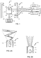
- a temperature controllable air outlet 10 includes a housing or duct 11 coupled to a supply of air (heated or cooled) 12. While duct 11 is preferably rectangular or square in cross-section, round, oval or other shapes can be used. Transition sections from round to rectangular, etc. can be provided in the duct work 13.
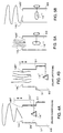
- outlet nibs 14L and 14R are shown in Figs. 6(a) and Fig. 6(b). As shown, the small nibs 14L and 14R provide the necessary throat geometry to provide the proper confinement to the downstream section of the island to support oscillation. This is true when the island 16 is positioned close to the outlet. (See patent 4,155,955 for a fuller explanation.)
- nib 14R With only one nib, such as nib 14R, as shown in Fig. 6(c), the jet is turned to the left. In addition, the jet appears to be mixing better on the nib affected side.
- an island member 16 has a base 17, parallel side wall surfaces 18 and 19, which form parallel passages 20 and 21.
- a pair of inwardly sloped wall surfaces 22, 23 are intersected by control element 24.
- Control element 24 is coupled by tube 26 to valve 27.
- Valve 27 has a chamber 28 in body member 29 and a valve seat 30 which is connected to tube 31 which leads to a source 32 of high pressure air just upstream of island 16.
- Valve member 33 has a control knob 34 so that the valve can be adjusted.
- Fig. 2(a) and Fig. 2(b) illustrate the response to changes in the valve setting extremes.
- the air through outlet 13 is oscillated with a wide fan angle and good mixing of air from source 12 with ambient air. Note the shed or Karman vortices KV.
- the jet temperature is modulated toward ambient.
- valve 27 When valve 27 is open, the device is rendered non-oscillatory by virtue of the higher pressure air from upstream of island 16.
- the air issuing through outlet 13 has a narrow fan angle with little mixing and the temperature is modulated toward the jet temperature.
- valve 27 is operated from fully closed to fully open positions and vice versa.
- Fig. 3 A modification of the remote control is illustrated in Fig. 3.
- high pressure air is also used to control oscillation.
- island 16' is provided with a Y-shaped passage 50 having downstream ports 51 and 52 in surfaces 22, 23 connected by a tube 53 to a remotely located control valve 54. Closing the valve thereby preventing the flow of high pressure air permits normal oscillation (Fig. 2(a)) with good mixing and temperature moderated toward ambient valves.
- Opening the valve 54 permits air flow, which progressively defeats oscillation to moderate the mixing and thus regulate the outlet temperature closer to the inlet.
- Fig. 4(a) and Fig. 4(b) are illustrated a physical linear translation of the island relative to duct 60.
- the island In Fig. 4(a), the island is in a position or mode to cause oscillation and is moved to a downstream position relative to constriction 51.
- the steady mode is shown in Fig. 4(b) wherein the island has been translated upstream of constriction 51.
- the island In Figs. 5(a) and 5(b), the island is rotary relative to the duct.
- the primed numerals correspond to elements previously described.
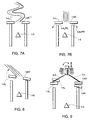
- Figs. 7A, 8 and 9 Other ways of controlling oscillation (and therefore the temperature) as well as integrating the temperature control with control of directionality of the jet is shown in Figs. 7A, 8 and 9.
- the effect of the nibs can be defeated by venting the air immediately upstream of the nib to ambient.
- the normal oscillatory condition of the oscillator shown in Fig. 7a is defeated by lifting nibs 14L and 14R to provide a vent path or gap 14UPL and 14UPR.
- the structure containing nibs 14L and 14R is pivoted so as to form a vent or gap on the left side, the jet will be deflected to the left as shown in Fig. 8, and to the right if one vent is formed on the right. This provides jet directionality control.
- a nib carrying structure can be nutated about the exit of the oscillator to left and right jet deflection, up and down to create dual vents and allow the jet to exit as shown in Fig. 7b or with the nibs properly positioned to sustain oscillation as shown in Fig. 7a and, therefore, produce modulation of the temperature to the ambient value.
- the nibs 14L and 14R are carried by frame members 50 and 51 which is coupled to central control members 51.
- a universal mounting ball 52 and socket joint 53 is carried on a threaded knob member 55, which is threadably engaged with ball 52.
- the threaded knob member When the threaded knob member is rotated, the nibs are moved toward and away from an oscillatory and non-oscillatory positions, respectively.
- the left 14L or right 14R nib can be pivoted to prevent one or the other side of the outlet and deflect the jet accordingly.
Landscapes
- Engineering & Computer Science (AREA)
- Mechanical Engineering (AREA)
- Combustion & Propulsion (AREA)
- General Engineering & Computer Science (AREA)
- Chemical & Material Sciences (AREA)
- Physics & Mathematics (AREA)
- Thermal Sciences (AREA)
- Heating, Cooling, Or Curing Plastics Or The Like In General (AREA)
- Paper (AREA)
- Commercial Cooking Devices (AREA)
- Glass Compositions (AREA)
- Temperature-Responsive Valves (AREA)
- Food-Manufacturing Devices (AREA)
- Electric Connection Of Electric Components To Printed Circuits (AREA)
- Nozzles (AREA)
- Fire-Detection Mechanisms (AREA)
- Duct Arrangements (AREA)
- Processing And Handling Of Plastics And Other Materials For Molding In General (AREA)
Claims (7)
- Procédé de commande de la température d'un effluent d'air provenant d'une sortie d'air chauffé ou refroidi vers l'air ambiant, caractérisé par les étapes consistant à:fournir un oscillateur aéraulique asservi en íle (16) dans ladite sortie d'air (10), ledit oscillateur aéraulique en íle (16) comportant des becs (14) sur les côtés de ladite sortie, pour assurer un confinement à la partie de l'íle (16) située en aval et pour soutenir l'oscillation, etcommander aérauliquement l'état d'oscillation et de non oscillation dudit oscillateur en íle (16) pour modérer le mélange dudit écoulement d'air traversant ladite sortie (10) avec l'air ambiant et ainsi moduler ledit effluent d'air.
- Procédé selon la revendication 1, dans lequel ledit oscillateur aéraulique comprend la commande de la directionnalité du vecteur d'air sortant de ladite sortie (10) pendant la durée de non oscillation dudit oscillateur aéraulique, en ventilant l'espace situé en amont de l'un desdits becs (14).
- Procédé selon la revendication 1, dans lequel la commande de l'état d'oscillation et de non oscillation dudit oscillateur (16) comprend l'étape consistant à fournir de l'air sous haute pression en un point de ladite íle (16) pour interrompre la formation de vortex de Karman autour de cette dernière.
- Procédé selon la revendication 1, dans lequel l'étape de commande comprend le déplacement de la position de ladite íle (16) par rapport à ladite sortie (10).
- Appareil pour commander la température d'un effluent d'air provenant d'une sortie (10) d'air chauffé ou refroidi, caractérisé parun oscillateur aéraulique asservi en íle (16) dans ladite sortie (10), présentant des becs (14) sur les côtés de ladite sortie, etun moyen pour commander l'état d'oscillation et de non oscillation dudit oscillateur aéraulique en íle (16) pour modérer le mélange dudit effluent d'air avec l'air ambiant et ainsi moduler ledit effluent d'air.
- Appareil selon la revendication 5, comportant un moyen pour commander la directionnalité d'un vecteur d'air sortant par ladite sortie pendant la durée de non oscillation dudit oscillateur aéraulique, en ventilant l'espace situé en amont de l'un desdits becs (14) respectifs.
- Appareil selon la revendication 5, dans lequel ledit moyen de commande comprend un moyen (32) pour délivrer de l'air sous haute pression en un point de ladite íle (16), pour interrompre l'oscillation.
Applications Claiming Priority (3)
| Application Number | Priority Date | Filing Date | Title |
|---|---|---|---|
| US07/982,646 US5385503A (en) | 1992-12-01 | 1992-12-01 | Temperature controller air outlet |
| US982646 | 1992-12-01 | ||
| PCT/US1993/011407 WO1994012831A1 (fr) | 1992-12-01 | 1993-11-30 | Sortie d'air comportant un ensemble de regulation de temperature |
Publications (3)
| Publication Number | Publication Date |
|---|---|
| EP0623202A1 EP0623202A1 (fr) | 1994-11-09 |
| EP0623202A4 EP0623202A4 (fr) | 1995-04-12 |
| EP0623202B1 true EP0623202B1 (fr) | 2000-02-02 |
Family
ID=25529378
Family Applications (1)
| Application Number | Title | Priority Date | Filing Date |
|---|---|---|---|
| EP94902367A Expired - Lifetime EP0623202B1 (fr) | 1992-12-01 | 1993-11-30 | Sortie d'air comportant un ensemble de regulation de temperature |
Country Status (8)
| Country | Link |
|---|---|
| US (1) | US5385503A (fr) |
| EP (1) | EP0623202B1 (fr) |
| JP (1) | JPH07504028A (fr) |
| AT (1) | ATE189516T1 (fr) |
| AU (1) | AU663038B2 (fr) |
| CA (1) | CA2128340C (fr) |
| DE (1) | DE69327783D1 (fr) |
| WO (1) | WO1994012831A1 (fr) |
Cited By (2)
| Publication number | Priority date | Publication date | Assignee | Title |
|---|---|---|---|---|
| US8834239B2 (en) | 2004-05-10 | 2014-09-16 | Behr Gmbh & Co. Kg | Air outlet in particular for a motor vehicle |
| US9296277B2 (en) | 2003-03-13 | 2016-03-29 | Mahle International Gmbh | Air exhausting device, in particular for a vehicle and corresponding method for exhausting air |
Families Citing this family (13)
| Publication number | Priority date | Publication date | Assignee | Title |
|---|---|---|---|---|
| US6159092A (en) * | 1998-08-31 | 2000-12-12 | Fickenscher America, L.L.C. | Air vent having two coplanar vane sets |
| US20020143373A1 (en) * | 2001-01-25 | 2002-10-03 | Courtnage Peter A. | System and method for therapeutic application of energy |
| DE10219696B4 (de) * | 2002-05-02 | 2007-10-11 | Daimlerchrysler Ag | Luftauslassdüse |
| US7503927B1 (en) | 2003-06-30 | 2009-03-17 | Vetanze Nelson W | Multiple therapy system and method |
| EP1708901B1 (fr) * | 2004-01-15 | 2010-07-21 | Behr GmbH & Co. KG | Procédé d'operation pour un système de chauffage, de ventilation ou de climatisation |
| US7195555B2 (en) * | 2004-02-05 | 2007-03-27 | Collins & Aikman Products Co. | Air duct outlets having return air passageways that facilitate oscillating air flow |
| DE102006017376A1 (de) * | 2006-04-11 | 2007-10-18 | Behr Gmbh & Co. Kg | Luftzuführungskanal |
| SE530624C2 (sv) * | 2006-12-06 | 2008-07-22 | Scania Cv Abp | Luftmunstycke |
| NL1036489C2 (nl) * | 2009-01-30 | 2010-08-02 | Biddle B V | Luchtgordijn-inrichting en werkwijze met een pulserende luchtstroom. |
| NL1036490C2 (nl) * | 2009-01-30 | 2010-08-02 | Biddle B V | Luchtgordijn-inrichting en werkwijze voor het realiseren van een luchtgordijn met snelheidsverloop in dwarsrichting. |
| US10959674B2 (en) | 2017-10-23 | 2021-03-30 | Datafeel Inc. | Communication devices, methods, and systems |
| KR20240083855A (ko) | 2020-10-30 | 2024-06-12 | 데이터필 인코포레이티드 | 웨어러블 데이터 통신 장치, 키트, 방법, 및 시스템 |
| CN116907087B (zh) * | 2023-08-14 | 2026-01-30 | 珠海格力节能环保制冷技术研究中心有限公司 | 室内机、空调器及其控制方法 |
Family Cites Families (8)
| Publication number | Priority date | Publication date | Assignee | Title |
|---|---|---|---|---|
| US3745906A (en) * | 1971-06-28 | 1973-07-17 | Nissan Motor | Defroster |
| US4151955A (en) * | 1977-10-25 | 1979-05-01 | Bowles Fluidics Corporation | Oscillating spray device |
| US4517881A (en) * | 1979-04-17 | 1985-05-21 | Bowles Fluidics Corporation | Sweeping air stream apparatus and method |
| JPS56148544U (fr) * | 1980-04-07 | 1981-11-09 | ||
| US4437392A (en) * | 1980-12-17 | 1984-03-20 | Bowles Fluidics Corporation | Sweeping air stream apparatus and method |
| JPS57101242A (en) * | 1980-12-17 | 1982-06-23 | Nissan Motor Co Ltd | Change-over device of fluid blow-off direction |
| US4774975A (en) * | 1984-09-17 | 1988-10-04 | Westinghouse Electric Corp. | Method and apparatus for providing oscillating contaminant-removal stream |
| US5099753A (en) * | 1990-09-06 | 1992-03-31 | Bowles Fluidics Corporation | Method and apparatus for maximizing transfer thermal energy contained in an oscilating or sweeping air jet to a plate surface |
-
1992
- 1992-12-01 US US07/982,646 patent/US5385503A/en not_active Expired - Fee Related
-
1993
- 1993-11-30 CA CA002128340A patent/CA2128340C/fr not_active Expired - Fee Related
- 1993-11-30 JP JP6513347A patent/JPH07504028A/ja active Pending
- 1993-11-30 EP EP94902367A patent/EP0623202B1/fr not_active Expired - Lifetime
- 1993-11-30 AT AT94902367T patent/ATE189516T1/de not_active IP Right Cessation
- 1993-11-30 AU AU56760/94A patent/AU663038B2/en not_active Ceased
- 1993-11-30 DE DE69327783T patent/DE69327783D1/de not_active Expired - Lifetime
- 1993-11-30 WO PCT/US1993/011407 patent/WO1994012831A1/fr not_active Ceased
Cited By (2)
| Publication number | Priority date | Publication date | Assignee | Title |
|---|---|---|---|---|
| US9296277B2 (en) | 2003-03-13 | 2016-03-29 | Mahle International Gmbh | Air exhausting device, in particular for a vehicle and corresponding method for exhausting air |
| US8834239B2 (en) | 2004-05-10 | 2014-09-16 | Behr Gmbh & Co. Kg | Air outlet in particular for a motor vehicle |
Also Published As
| Publication number | Publication date |
|---|---|
| JPH07504028A (ja) | 1995-04-27 |
| EP0623202A1 (fr) | 1994-11-09 |
| US5385503A (en) | 1995-01-31 |
| CA2128340C (fr) | 1999-08-24 |
| CA2128340A1 (fr) | 1994-06-09 |
| DE69327783D1 (de) | 2000-03-09 |
| EP0623202A4 (fr) | 1995-04-12 |
| ATE189516T1 (de) | 2000-02-15 |
| AU663038B2 (en) | 1995-09-21 |
| AU5676094A (en) | 1994-06-22 |
| WO1994012831A1 (fr) | 1994-06-09 |
Similar Documents
| Publication | Publication Date | Title |
|---|---|---|
| AU663038B2 (en) | Temperature controller outlet | |
| US4556172A (en) | Flow direction controller | |
| US4677904A (en) | Fluid flow control assembly | |
| JPH09262296A (ja) | 人工呼吸器のダイヤフラム中立位置制御装置 | |
| US11390144B2 (en) | Air outlet for controlling an air flow | |
| KR20190121963A (ko) | 차량용 에어벤트 | |
| US20220161634A1 (en) | Ventilation system | |
| US5259815A (en) | Air outlet with aperiodic oscillation | |
| JP4328140B2 (ja) | 自動車用空気分配デバイス | |
| US4424937A (en) | Fluid deflecting assembly | |
| EP0203432B1 (fr) | Dispositif et procédé de distribution d'air | |
| JPH0362924B2 (fr) | ||
| US11993135B2 (en) | Air vent for a vehicle | |
| JPS6222052B2 (fr) | ||
| WO1985000783A1 (fr) | Appareil de degivrage de pare-brise de vehicule necessitant moins de place sur le tableau de bord | |
| JPH0127937Y2 (fr) | ||
| JPH0330064B2 (fr) | ||
| US3989187A (en) | Air-conditioning system apparatus | |
| CN116907087A (zh) | 室内机、空调器及其控制方法 | |
| JPS6099949A (ja) | 空気吹出口 | |
| JPS6364814A (ja) | 車輌用空気調和装置 | |
| JPH0226142B2 (fr) | ||
| KR0127173Y1 (ko) | 자동차용 공기조화 장치의 케이스 | |
| JPS648253B2 (fr) | ||
| JPS5810653Y2 (ja) | 自動車用空調装置の温度コントロ−ル装置 |
Legal Events
| Date | Code | Title | Description |
|---|---|---|---|
| PUAI | Public reference made under article 153(3) epc to a published international application that has entered the european phase |
Free format text: ORIGINAL CODE: 0009012 |
|
| 17P | Request for examination filed |
Effective date: 19940720 |
|
| AK | Designated contracting states |
Kind code of ref document: A1 Designated state(s): AT DE ES FR GB IT SE |
|
| A4 | Supplementary search report drawn up and despatched |
Effective date: 19950224 |
|
| AK | Designated contracting states |
Kind code of ref document: A4 Designated state(s): AT DE ES FR GB IT SE |
|
| 17Q | First examination report despatched |
Effective date: 19961024 |
|
| GRAG | Despatch of communication of intention to grant |
Free format text: ORIGINAL CODE: EPIDOS AGRA |
|
| GRAG | Despatch of communication of intention to grant |
Free format text: ORIGINAL CODE: EPIDOS AGRA |
|
| GRAH | Despatch of communication of intention to grant a patent |
Free format text: ORIGINAL CODE: EPIDOS IGRA |
|
| GRAH | Despatch of communication of intention to grant a patent |
Free format text: ORIGINAL CODE: EPIDOS IGRA |
|
| GRAA | (expected) grant |
Free format text: ORIGINAL CODE: 0009210 |
|
| AK | Designated contracting states |
Kind code of ref document: B1 Designated state(s): AT DE ES FR GB IT SE |
|
| PG25 | Lapsed in a contracting state [announced via postgrant information from national office to epo] |
Ref country code: IT Free format text: LAPSE BECAUSE OF FAILURE TO SUBMIT A TRANSLATION OF THE DESCRIPTION OR TO PAY THE FEE WITHIN THE PRESCRIBED TIME-LIMIT;WARNING: LAPSES OF ITALIAN PATENTS WITH EFFECTIVE DATE BEFORE 2007 MAY HAVE OCCURRED AT ANY TIME BEFORE 2007. THE CORRECT EFFECTIVE DATE MAY BE DIFFERENT FROM THE ONE RECORDED. Effective date: 20000202 Ref country code: FR Free format text: LAPSE BECAUSE OF FAILURE TO SUBMIT A TRANSLATION OF THE DESCRIPTION OR TO PAY THE FEE WITHIN THE PRESCRIBED TIME-LIMIT Effective date: 20000202 Ref country code: ES Free format text: THE PATENT HAS BEEN ANNULLED BY A DECISION OF A NATIONAL AUTHORITY Effective date: 20000202 Ref country code: AT Free format text: LAPSE BECAUSE OF FAILURE TO SUBMIT A TRANSLATION OF THE DESCRIPTION OR TO PAY THE FEE WITHIN THE PRESCRIBED TIME-LIMIT Effective date: 20000202 |
|
| REF | Corresponds to: |
Ref document number: 189516 Country of ref document: AT Date of ref document: 20000215 Kind code of ref document: T |
|
| REF | Corresponds to: |
Ref document number: 69327783 Country of ref document: DE Date of ref document: 20000309 |
|
| PG25 | Lapsed in a contracting state [announced via postgrant information from national office to epo] |
Ref country code: SE Free format text: LAPSE BECAUSE OF FAILURE TO SUBMIT A TRANSLATION OF THE DESCRIPTION OR TO PAY THE FEE WITHIN THE PRESCRIBED TIME-LIMIT Effective date: 20000502 |
|
| PG25 | Lapsed in a contracting state [announced via postgrant information from national office to epo] |
Ref country code: DE Free format text: LAPSE BECAUSE OF FAILURE TO SUBMIT A TRANSLATION OF THE DESCRIPTION OR TO PAY THE FEE WITHIN THE PRESCRIBED TIME-LIMIT Effective date: 20000503 |
|
| EN | Fr: translation not filed | ||
| PG25 | Lapsed in a contracting state [announced via postgrant information from national office to epo] |
Ref country code: GB Free format text: LAPSE BECAUSE OF NON-PAYMENT OF DUE FEES Effective date: 20001130 |
|
| PLBE | No opposition filed within time limit |
Free format text: ORIGINAL CODE: 0009261 |
|
| STAA | Information on the status of an ep patent application or granted ep patent |
Free format text: STATUS: NO OPPOSITION FILED WITHIN TIME LIMIT |
|
| 26N | No opposition filed | ||
| GBPC | Gb: european patent ceased through non-payment of renewal fee |
Effective date: 20001130 |