EP0623395B1 - Circuit pour amortir un transducteur d'ultrasons - Google Patents
Circuit pour amortir un transducteur d'ultrasons Download PDFInfo
- Publication number
- EP0623395B1 EP0623395B1 EP94104661A EP94104661A EP0623395B1 EP 0623395 B1 EP0623395 B1 EP 0623395B1 EP 94104661 A EP94104661 A EP 94104661A EP 94104661 A EP94104661 A EP 94104661A EP 0623395 B1 EP0623395 B1 EP 0623395B1
- Authority
- EP
- European Patent Office
- Prior art keywords
- circuit arrangement
- generator
- arrangement according
- period
- envelope
- Prior art date
- Legal status (The legal status is an assumption and is not a legal conclusion. Google has not performed a legal analysis and makes no representation as to the accuracy of the status listed.)
- Expired - Lifetime
Links
Images

Classifications
-
- G—PHYSICS
- G01—MEASURING; TESTING
- G01S—RADIO DIRECTION-FINDING; RADIO NAVIGATION; DETERMINING DISTANCE OR VELOCITY BY USE OF RADIO WAVES; LOCATING OR PRESENCE-DETECTING BY USE OF THE REFLECTION OR RERADIATION OF RADIO WAVES; ANALOGOUS ARRANGEMENTS USING OTHER WAVES
- G01S15/00—Systems using the reflection or reradiation of acoustic waves, e.g. sonar systems
- G01S15/02—Systems using the reflection or reradiation of acoustic waves, e.g. sonar systems using reflection of acoustic waves
- G01S15/06—Systems determining the position data of a target
- G01S15/08—Systems for measuring distance only
- G01S15/10—Systems for measuring distance only using transmission of interrupted, pulse-modulated waves
- G01S15/102—Systems for measuring distance only using transmission of interrupted, pulse-modulated waves using transmission of pulses having some particular characteristics
-
- B—PERFORMING OPERATIONS; TRANSPORTING
- B06—GENERATING OR TRANSMITTING MECHANICAL VIBRATIONS IN GENERAL
- B06B—METHODS OR APPARATUS FOR GENERATING OR TRANSMITTING MECHANICAL VIBRATIONS OF INFRASONIC, SONIC, OR ULTRASONIC FREQUENCY, e.g. FOR PERFORMING MECHANICAL WORK IN GENERAL
- B06B1/00—Methods or apparatus for generating mechanical vibrations of infrasonic, sonic, or ultrasonic frequency
- B06B1/02—Methods or apparatus for generating mechanical vibrations of infrasonic, sonic, or ultrasonic frequency making use of electrical energy
- B06B1/0207—Driving circuits
- B06B1/0215—Driving circuits for generating pulses, e.g. bursts of oscillations, envelopes
-
- B—PERFORMING OPERATIONS; TRANSPORTING
- B60—VEHICLES IN GENERAL
- B60Q—ARRANGEMENT OF SIGNALLING OR LIGHTING DEVICES, THE MOUNTING OR SUPPORTING THEREOF OR CIRCUITS THEREFOR, FOR VEHICLES IN GENERAL
- B60Q9/00—Arrangement or adaptation of signal devices not provided for in one of main groups B60Q1/00 - B60Q7/00, e.g. haptic signalling
- B60Q9/002—Arrangement or adaptation of signal devices not provided for in one of main groups B60Q1/00 - B60Q7/00, e.g. haptic signalling for parking purposes, e.g. for warning the driver that his vehicle has contacted or is about to contact an obstacle
- B60Q9/004—Arrangement or adaptation of signal devices not provided for in one of main groups B60Q1/00 - B60Q7/00, e.g. haptic signalling for parking purposes, e.g. for warning the driver that his vehicle has contacted or is about to contact an obstacle using wave sensors
- B60Q9/006—Arrangement or adaptation of signal devices not provided for in one of main groups B60Q1/00 - B60Q7/00, e.g. haptic signalling for parking purposes, e.g. for warning the driver that his vehicle has contacted or is about to contact an obstacle using wave sensors using a distance sensor
-
- G—PHYSICS
- G01—MEASURING; TESTING
- G01S—RADIO DIRECTION-FINDING; RADIO NAVIGATION; DETERMINING DISTANCE OR VELOCITY BY USE OF RADIO WAVES; LOCATING OR PRESENCE-DETECTING BY USE OF THE REFLECTION OR RERADIATION OF RADIO WAVES; ANALOGOUS ARRANGEMENTS USING OTHER WAVES
- G01S15/00—Systems using the reflection or reradiation of acoustic waves, e.g. sonar systems
- G01S15/88—Sonar systems specially adapted for specific applications
- G01S15/93—Sonar systems specially adapted for specific applications for anti-collision purposes
- G01S15/931—Sonar systems specially adapted for specific applications for anti-collision purposes of land vehicles
-
- G—PHYSICS
- G01—MEASURING; TESTING
- G01S—RADIO DIRECTION-FINDING; RADIO NAVIGATION; DETERMINING DISTANCE OR VELOCITY BY USE OF RADIO WAVES; LOCATING OR PRESENCE-DETECTING BY USE OF THE REFLECTION OR RERADIATION OF RADIO WAVES; ANALOGOUS ARRANGEMENTS USING OTHER WAVES
- G01S7/00—Details of systems according to groups G01S13/00, G01S15/00, G01S17/00
- G01S7/52—Details of systems according to groups G01S13/00, G01S15/00, G01S17/00 of systems according to group G01S15/00
- G01S7/523—Details of pulse systems
- G01S7/524—Transmitters
-
- H—ELECTRICITY
- H04—ELECTRIC COMMUNICATION TECHNIQUE
- H04R—LOUDSPEAKERS, MICROPHONES, GRAMOPHONE PICK-UPS OR LIKE ACOUSTIC ELECTROMECHANICAL TRANSDUCERS; ELECTRIC HEARING AIDS; PUBLIC ADDRESS SYSTEMS
- H04R3/00—Circuits for transducers
- H04R3/002—Damping circuit arrangements for transducers, e.g. motional feedback circuits
Definitions
- the invention relates to a circuit arrangement for damping an ultrasonic transducer according to the preamble of the main claim.
- a circuit arrangement is known from DE-C-862 274.
- the circuit arrangement according to the invention with the characterizing features of the main claim has the advantage that the decay characteristic and the decay duration of the transmission signal can be predetermined by the control curve in such a way that the generation of the secondary spectra and the noise development is significantly reduced. Occurring manufacturing tolerances are advantageously influenced, so that a quick measurement sequence is possible even for short distances.
- the generator for influencing the control voltage has a means which lowers the voltage to zero within a predetermined period of time. This is advantageously achieved in that the amplitude of the transmission pulses is reduced by a reduced excitation of the ultrasound transducer.
- An RC element which has a low-pass characteristic, is particularly easy to influence.
- the proposed circuit measures also advantageously reduce the amplitudes of the frequency secondary spectra during the switch-off process.
- the lower excitation towards the end of the impls enables shorter switching intervals or operating intervals of the ultrasonic transducer.
- the secondary spectra are reduced by amplitude modulation of the output voltage and thus a reduction in the switch-off noise takes place. This is achieved in that the decay period initially drops to a grade rule value that is constant for a certain period of time. The output voltage is only switched off after this period.
- the implementation with simple and inexpensive components such as resistors and diodes is particularly advantageous.
- the semiconductor bridge circuit provides a simple control option for the sensor, as a result of which the voltage swing for the ultrasonic sensor in the bridge branch is approximately doubled.
- An advantageous application is in the motor vehicle for determining the distance when parking.
- FIGS. 1 and 2 two exemplary embodiments of the invention are shown in FIGS. 1 and 2.
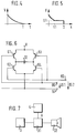
- Figure 3 shows a block diagram of the arrangement and Figures 4 and 5 show diagrams with decay curves,
- Figure 6 shows a bridge circuit and
- Figure 7 shows another block diagram.
- FIG. 1 shows a generator 4, which is connected to a control 3 for an ultrasound sensor (US sensor), not shown.
- the generator 4 has a high-impedance source 1, which is connected to a control input of the control 3 via a capacitor 2 connected in parallel.
- the high-resistance source 1 has a voltage source with a high-resistance internal resistance, the output voltage of which can be controlled by charging and discharging the capacitor 2.
- the output of the control 3 is connected to the input of the driver stage 31.
- a control curve (envelope curve V) for the decay behavior of the US sensor 32 can be specified in accordance with the diagram in FIG. 4 (FIG. 3).
- the control 3 is known per se, for example, from the publication 'Ultrasound location system for industrial trucks', Prof. Wellhausen, Electronics 9 / 27.4.1990, pages 100 to 105.
- FIG. 2 shows a further exemplary embodiment in which the generator 4 has a low-resistance source 20 in addition to the high-resistance source 1.
- the arrangement corresponds to that of FIG. 1, the low-resistance source 20 being connected in parallel with the output of the high-resistance source 1 via a diode 21.
- the output is connected to the control 3 and its output to the driver stage 31.
- FIG. 3 shows a basic block diagram, the generator 4, the control 3, the driver stage 31 and the US sensor 32 being connected in series.
- the US sensor 32 is supplied by the control voltage with the envelope V of the driver stage 31.
- the driver stage 31 contains circuit breakers that deliver the control current or the control voltage in time with the control 3.
- a semiconductor bridge circuit can be provided, in the branches of which the transistors 61, 62, 63, 64 are arranged.
- the US sensor 32 is arranged in the bridge branch, while the generator 4 supplies the bridge with the voltage V in accordance with FIG.
- the transistors 61, 62, 63, 64 are activated in phase opposition with the voltages U S1 and U S2 .
- the mode of operation of this circuit arrangement is explained in more detail with reference to FIGS. 4 and 5.
- the basic idea of influencing the decay curve of the US sensor 32 by means of electronic switching elements is implemented in a particularly simple and advantageous manner in accordance with the block diagram in FIG. 1.
- the capacitor 2 results in the curve shown in FIG. 4 as the envelope curve for the voltage amplitude of the transmit pulses, the envelope curve falling within the time T from the maximum value V approximately towards the value zero.
- the decay time depending on the exponential function shown, depends on the capacitance of the capacitor 2 and the internal resistance of the control with driver stage 3. By varying the values, almost any desired decay curve can be achieved.
- the decay curve (envelope curve) of FIG. 5 is achieved with the circuit arrangement according to FIG.
- the envelope falls at the time t1 to the voltage value U1 in a manner similar to that in the diagram in FIG. 4.
- a voltage is fed into the capacitor C2 via the diode 21, so that the envelope in the time phase t1 until T is approximately constant.
- the amplitude within this period is significantly lower than the maximum value of the amplitude. This advantageously has the effect that, because of the reduced output power, the emitted secondary spectra do not lead to undesired noises.
- the holding level U1 is kept so low that the US sensor 32 continues to be constantly excited during the pulse duration T. After the pulse duration T has elapsed, a dead phase begins with the subsequent measuring phase.
- a preferred application of the circuit arrangement according to the invention is an ultrasound distance measurement, as is used, for example, as a parking aid for motor vehicles.
- Ultrasonic distance measurement is known per se from EP-0 152 895 B1.
- a contactless distance measurement is also known from EP 0 320 695 A1.
- the electroacoustic transducer designed as an ultrasonic sensor is already known from DE 34 41 684 A1.
Landscapes
- Engineering & Computer Science (AREA)
- Radar, Positioning & Navigation (AREA)
- Remote Sensing (AREA)
- Physics & Mathematics (AREA)
- Computer Networks & Wireless Communication (AREA)
- General Physics & Mathematics (AREA)
- Acoustics & Sound (AREA)
- Mechanical Engineering (AREA)
- Signal Processing (AREA)
- Transportation (AREA)
- Human Computer Interaction (AREA)
- Measurement Of Velocity Or Position Using Acoustic Or Ultrasonic Waves (AREA)
Claims (7)
- Circuit pour amortir un convertisseur ultrasons conçu pour fonctionner tant comme émetteur et comme récepteur, le circuit ayant un générateur (4) et ce générateur (4) est réalisé pour que la tension de commande (V) du convertisseur ultrasons (32) soit commandée pour que l'amplitude, correspondant à la tension de commande du signal ultrasons, émis, s'atténue suivant une courbe enveloppante prédéterminée pour la durée d'atténuation (V),
caractérisé en ce que
le générateur (4) comprend un autre moyen (20, 21) qui fait tomber la courbe-enveloppe (V), prédéterminée, à l'intérieur d'une période (t1), tout d'abord à une valeur de tension (U1) essentiellement différente de zéro et la tension (U1) de la courbe-enveloppe (V) pour une certaine durée (T-t1) est alors pratiquement constante. - Montage selon la revendication 1,
caractérisé en ce que
le générateur (4) comprend un moyen (2) qui fait chuter la courbe-enveloppe prédéterminée (V) par la tension de commande après une durée pour faire descendre sensiblement jusqu'à zéro. - Circuit selon la revendication 2,
caractérisé en ce que
le moyen (2) est un élément RC (1, 2) en forme de filtre passe-bas. - Circuit selon la revendication 1,
caractérisé en ce qu'
il comprend en outre un autre moyen (20, 21) avec une source faiblement ohmique (20) précédée par un circuit de commande (3), et ayant une diode (21) branchée en série. - Circuit selon l'une des revendications précédentes,
caractérisé en ce que
le convertisseur ultrasons (32) se trouve dans la branche transversale d'un circuit en pont à transistors (61, 62, 63, 64), les transistors (61, 62, 63, 64) étant commandés en opposition de phase par leurs entrées (US1, US2), en cas de fonctionnement et pour l'alimentation des ponts, il y a une liaison avec le générateur (4). - Circuit selon l'une des revendications précédentes,
caractérisé en ce que
le montage en pont est applicable pour mesurer la distance par rapport à un véhicule. - Circuit selon la revendication 6,
caractérisé en ce que
le circuit de commutation est applicable à une assistance aux manoeuvres de garage.
Applications Claiming Priority (2)
| Application Number | Priority Date | Filing Date | Title |
|---|---|---|---|
| DE4314247A DE4314247A1 (de) | 1993-04-30 | 1993-04-30 | Schaltungsanordnung zur Dämpfung eines Ultraschallwandlers |
| DE4314247 | 1993-04-30 |
Publications (2)
| Publication Number | Publication Date |
|---|---|
| EP0623395A1 EP0623395A1 (fr) | 1994-11-09 |
| EP0623395B1 true EP0623395B1 (fr) | 1997-01-15 |
Family
ID=6486814
Family Applications (1)
| Application Number | Title | Priority Date | Filing Date |
|---|---|---|---|
| EP94104661A Expired - Lifetime EP0623395B1 (fr) | 1993-04-30 | 1994-03-24 | Circuit pour amortir un transducteur d'ultrasons |
Country Status (4)
| Country | Link |
|---|---|
| EP (1) | EP0623395B1 (fr) |
| JP (1) | JP3654596B2 (fr) |
| KR (1) | KR100334193B1 (fr) |
| DE (2) | DE4314247A1 (fr) |
Cited By (3)
| Publication number | Priority date | Publication date | Assignee | Title |
|---|---|---|---|---|
| EP3208634A1 (fr) | 2016-02-17 | 2017-08-23 | ELMOS Semiconductor Aktiengesellschaft | Systeme de mesure d'ultrasons, en particulier destine a mesurer la distance et/ou en tant qu'aide au stationnement dans des vehicules automobiles |
| DE102016103514A1 (de) | 2016-02-29 | 2017-08-31 | Valeo Schalter Und Sensoren Gmbh | Filtereinrichtung zum Filtern einer Versorgungsspannung eines Ultraschallsensors eines Kraftfahrzeugs, Ultraschallsensorvorrichtung sowie Kraftfahrzeug |
| US10361559B2 (en) | 2017-10-27 | 2019-07-23 | Valeo Schalter Und Sensoren Gmbh | Dynamic filtering device for sensor |
Families Citing this family (8)
| Publication number | Priority date | Publication date | Assignee | Title |
|---|---|---|---|---|
| DE10314922A1 (de) * | 2003-04-01 | 2004-10-14 | Endress + Hauser Gmbh + Co. Kg | Mit Ultraschall arbeitendes Füllstandsmeßgerät |
| DE102006054605A1 (de) * | 2006-11-20 | 2008-05-21 | Robert Bosch Gmbh | Abstandsmessverfahren und Abstandsmessvorrichtung |
| DE102010062930A1 (de) | 2010-12-13 | 2012-06-14 | Robert Bosch Gmbh | Verfahren zur Erfassung eines Objekts in einem Umfeld und Vorrichtung zur Erzeugung eines Ultraschallsignals |
| DE102011083337A1 (de) * | 2011-09-23 | 2013-03-28 | Robert Bosch Gmbh | Verfahren zur Erfassung der Fahrzeugumgebung eines Fahrzeuges mittels Ultraschall und Vorrichtung zum Durchführen des Verfahrens |
| DE102011089542A1 (de) | 2011-12-22 | 2013-06-27 | Robert Bosch Gmbh | Verfahren und Schaltungsanordnung zur Ansteuerung eines Ultraschallsensors |
| DE102012201100A1 (de) | 2012-01-26 | 2013-08-01 | Robert Bosch Gmbh | Ansteuerungsschaltung und Verfahren zur aktiven Dämpfung eines Ultraschallwandlers, sowie Ultraschall-Messsystem |
| DE102012201920A1 (de) | 2012-02-09 | 2013-08-14 | Robert Bosch Gmbh | Verfahren und Messsystem zum Detektieren von Objekten mittels Ultraschall |
| CN121589020A (zh) * | 2024-08-21 | 2026-03-03 | 艾尔默斯半导体欧洲股份公司 | 用于控制用于生成超声波的超声换能器的装置 |
Citations (1)
| Publication number | Priority date | Publication date | Assignee | Title |
|---|---|---|---|---|
| EP0152895A2 (fr) * | 1984-02-18 | 1985-08-28 | Bayerische Motoren Werke Aktiengesellschaft, Patentabteilung AJ-3 | Circuit pour télémètre ultrasonore |
Family Cites Families (1)
| Publication number | Priority date | Publication date | Assignee | Title |
|---|---|---|---|---|
| DE862274C (de) * | 1942-02-08 | 1953-01-08 | Atlas Werke Ag | Vorrichtung zum Impulsbetrieb von Elektromagneten, insbesondere von Magnetostriktionsschwingern zur Erzeugung von Schallimpulsen |
-
1993
- 1993-04-30 DE DE4314247A patent/DE4314247A1/de not_active Withdrawn
-
1994
- 1994-03-24 DE DE59401571T patent/DE59401571D1/de not_active Expired - Fee Related
- 1994-03-24 EP EP94104661A patent/EP0623395B1/fr not_active Expired - Lifetime
- 1994-04-27 JP JP09006494A patent/JP3654596B2/ja not_active Expired - Fee Related
- 1994-04-28 KR KR1019940009581A patent/KR100334193B1/ko not_active Expired - Fee Related
Patent Citations (1)
| Publication number | Priority date | Publication date | Assignee | Title |
|---|---|---|---|---|
| EP0152895A2 (fr) * | 1984-02-18 | 1985-08-28 | Bayerische Motoren Werke Aktiengesellschaft, Patentabteilung AJ-3 | Circuit pour télémètre ultrasonore |
Cited By (4)
| Publication number | Priority date | Publication date | Assignee | Title |
|---|---|---|---|---|
| EP3208634A1 (fr) | 2016-02-17 | 2017-08-23 | ELMOS Semiconductor Aktiengesellschaft | Systeme de mesure d'ultrasons, en particulier destine a mesurer la distance et/ou en tant qu'aide au stationnement dans des vehicules automobiles |
| DE102016103514A1 (de) | 2016-02-29 | 2017-08-31 | Valeo Schalter Und Sensoren Gmbh | Filtereinrichtung zum Filtern einer Versorgungsspannung eines Ultraschallsensors eines Kraftfahrzeugs, Ultraschallsensorvorrichtung sowie Kraftfahrzeug |
| WO2017148633A1 (fr) | 2016-02-29 | 2017-09-08 | Valeo Schalter Und Sensoren Gmbh | Dispositif de filtrage pour filtrer une tension d'alimentation d'un capteur à ultrasons d'un véhicule à moteur, dispositif de capteur à ultrasons et véhicule à moteur |
| US10361559B2 (en) | 2017-10-27 | 2019-07-23 | Valeo Schalter Und Sensoren Gmbh | Dynamic filtering device for sensor |
Also Published As
| Publication number | Publication date |
|---|---|
| EP0623395A1 (fr) | 1994-11-09 |
| KR940025384A (ko) | 1994-11-19 |
| DE59401571D1 (de) | 1997-02-27 |
| KR100334193B1 (ko) | 2002-09-05 |
| JPH06347537A (ja) | 1994-12-22 |
| DE4314247A1 (de) | 1994-11-03 |
| JP3654596B2 (ja) | 2005-06-02 |
Similar Documents
| Publication | Publication Date | Title |
|---|---|---|
| EP0033508B1 (fr) | Circuit pour transmettre et recevoir alternativement avec un seul émetteur-transducteur du son | |
| EP0623395B1 (fr) | Circuit pour amortir un transducteur d'ultrasons | |
| EP2223151A1 (fr) | Fonction de capteur pour commande avec fréquence d'émission variable afin de déceler l'encrassement | |
| EP2780125B1 (fr) | Transducteur ultrasonique et dispositif correspondant de surveillance de l'environnement d'un véhicule | |
| DE3347442A1 (de) | Einrichtung zur abstandsmessung, insbesondere fuer kraftfahrzeuge | |
| DE3513270A1 (de) | Einrichtung zur abstandsmessung, insbesondere fuer kraftfahrzeuge | |
| DE102004058665A1 (de) | Vorrichtung und Verfahren zur Dämpfung eines Parallelschwingkreises | |
| DE19720519A1 (de) | Vorrichtung zur Feststellung und/oder Überwachung eines Füllstandes eines Mediums in einem Behälter | |
| DE4414746C2 (de) | Sende-Empfangsschaltung für ein akustisches Pulsecho-Entfernungsmeßsystem | |
| EP0320695A1 (fr) | Dispositif de mesure de distance sans contacts | |
| EP4721880A2 (fr) | Dispositif de commande d'un transducteur ultrasonore et dispositif de mesure ultrasonore muni d'un tel dispositif de commande pour le transducteur ultrasonore | |
| EP1977190B1 (fr) | Appareil de mesure de distance | |
| WO2017148633A1 (fr) | Dispositif de filtrage pour filtrer une tension d'alimentation d'un capteur à ultrasons d'un véhicule à moteur, dispositif de capteur à ultrasons et véhicule à moteur | |
| DE10328113B4 (de) | Vorrichtung zum Betreiben einer schwingfähigen Einheit eines Vibrationsresonators | |
| EP2692451B1 (fr) | Circuit électrique pour le fonctionnement d'une unité émettrice-réceptrice | |
| DE19721835C2 (de) | Schaltungsanordnung zum Betreiben eines Abstandssensors, insbesondere eines Ultraschallsensors | |
| EP0343403A1 (fr) | Circuit pour l'auto-excitation d'un oscillateur mécanique jusqu'à sa fréquence de résonance propre | |
| DE102007062460A1 (de) | Ultraschallsensor | |
| DE102020132634A1 (de) | Ultraschallsensorsystem für ein kraftfahrzeug und verfahren zum betreiben des ultraschallsensorsystems | |
| DE3602857A1 (de) | Einrichtung zur abstandsmessung, insbesondere fuer kraftfahrzeuge | |
| EP2904424B1 (fr) | Suppression de l'oscillation d'un convertisseur pour la détection environnementale | |
| DE102010062930A1 (de) | Verfahren zur Erfassung eines Objekts in einem Umfeld und Vorrichtung zur Erzeugung eines Ultraschallsignals | |
| DE4200194C2 (de) | Schwingförderanordnung | |
| DE19636574C1 (de) | Wegfahrsperre für ein Kraftfahrzeug | |
| EP0327656B1 (fr) | Commutateur de proximité à ultrasons |
Legal Events
| Date | Code | Title | Description |
|---|---|---|---|
| PUAI | Public reference made under article 153(3) epc to a published international application that has entered the european phase |
Free format text: ORIGINAL CODE: 0009012 |
|
| AK | Designated contracting states |
Kind code of ref document: A1 Designated state(s): DE FR GB IT |
|
| 17P | Request for examination filed |
Effective date: 19950509 |
|
| 17Q | First examination report despatched |
Effective date: 19960112 |
|
| GRAG | Despatch of communication of intention to grant |
Free format text: ORIGINAL CODE: EPIDOS AGRA |
|
| GRAH | Despatch of communication of intention to grant a patent |
Free format text: ORIGINAL CODE: EPIDOS IGRA |
|
| GRAH | Despatch of communication of intention to grant a patent |
Free format text: ORIGINAL CODE: EPIDOS IGRA |
|
| GRAA | (expected) grant |
Free format text: ORIGINAL CODE: 0009210 |
|
| AK | Designated contracting states |
Kind code of ref document: B1 Designated state(s): DE FR GB IT |
|
| ET | Fr: translation filed | ||
| REF | Corresponds to: |
Ref document number: 59401571 Country of ref document: DE Date of ref document: 19970227 |
|
| ITF | It: translation for a ep patent filed | ||
| GBT | Gb: translation of ep patent filed (gb section 77(6)(a)/1977) |
Effective date: 19970320 |
|
| PLBE | No opposition filed within time limit |
Free format text: ORIGINAL CODE: 0009261 |
|
| STAA | Information on the status of an ep patent application or granted ep patent |
Free format text: STATUS: NO OPPOSITION FILED WITHIN TIME LIMIT |
|
| 26N | No opposition filed | ||
| REG | Reference to a national code |
Ref country code: GB Ref legal event code: IF02 |
|
| PGFP | Annual fee paid to national office [announced via postgrant information from national office to epo] |
Ref country code: IT Payment date: 20060331 Year of fee payment: 13 |
|
| PGFP | Annual fee paid to national office [announced via postgrant information from national office to epo] |
Ref country code: DE Payment date: 20060516 Year of fee payment: 13 |
|
| PGFP | Annual fee paid to national office [announced via postgrant information from national office to epo] |
Ref country code: GB Payment date: 20070323 Year of fee payment: 14 |
|
| PG25 | Lapsed in a contracting state [announced via postgrant information from national office to epo] |
Ref country code: DE Free format text: LAPSE BECAUSE OF NON-PAYMENT OF DUE FEES Effective date: 20071002 |
|
| PGFP | Annual fee paid to national office [announced via postgrant information from national office to epo] |
Ref country code: FR Payment date: 20070321 Year of fee payment: 14 |
|
| GBPC | Gb: european patent ceased through non-payment of renewal fee |
Effective date: 20080324 |
|
| REG | Reference to a national code |
Ref country code: FR Ref legal event code: ST Effective date: 20081125 |
|
| PG25 | Lapsed in a contracting state [announced via postgrant information from national office to epo] |
Ref country code: FR Free format text: LAPSE BECAUSE OF NON-PAYMENT OF DUE FEES Effective date: 20080331 |
|
| PG25 | Lapsed in a contracting state [announced via postgrant information from national office to epo] |
Ref country code: GB Free format text: LAPSE BECAUSE OF NON-PAYMENT OF DUE FEES Effective date: 20080324 |
|
| PG25 | Lapsed in a contracting state [announced via postgrant information from national office to epo] |
Ref country code: IT Free format text: LAPSE BECAUSE OF NON-PAYMENT OF DUE FEES Effective date: 20070324 |