EP0623420B1 - Dispositif de transport et de fixation - Google Patents
Dispositif de transport et de fixation Download PDFInfo
- Publication number
- EP0623420B1 EP0623420B1 EP94102023A EP94102023A EP0623420B1 EP 0623420 B1 EP0623420 B1 EP 0623420B1 EP 94102023 A EP94102023 A EP 94102023A EP 94102023 A EP94102023 A EP 94102023A EP 0623420 B1 EP0623420 B1 EP 0623420B1
- Authority
- EP
- European Patent Office
- Prior art keywords
- vices
- slide
- transport
- workpiece
- holding device
- Prior art date
- Legal status (The legal status is an assumption and is not a legal conclusion. Google has not performed a legal analysis and makes no representation as to the accuracy of the status listed.)
- Expired - Lifetime
Links
- 238000003754 machining Methods 0.000 claims abstract description 8
- 239000012530 fluid Substances 0.000 claims 2
- 230000006835 compression Effects 0.000 description 6
- 238000007906 compression Methods 0.000 description 6
- 238000000034 method Methods 0.000 description 4
- 239000002699 waste material Substances 0.000 description 3
- 238000010276 construction Methods 0.000 description 1
- 230000008878 coupling Effects 0.000 description 1
- 238000010168 coupling process Methods 0.000 description 1
- 238000005859 coupling reaction Methods 0.000 description 1
- 238000013022 venting Methods 0.000 description 1
Images
Classifications
-
- B—PERFORMING OPERATIONS; TRANSPORTING
- B21—MECHANICAL METAL-WORKING WITHOUT ESSENTIALLY REMOVING MATERIAL; PUNCHING METAL
- B21D—WORKING OR PROCESSING OF SHEET METAL OR METAL TUBES, RODS OR PROFILES WITHOUT ESSENTIALLY REMOVING MATERIAL; PUNCHING METAL
- B21D43/00—Feeding, positioning or storing devices combined with, or arranged in, or specially adapted for use in connection with, apparatus for working or processing sheet metal, metal tubes or metal profiles; Associations therewith of cutting devices
- B21D43/28—Associations of cutting devices therewith
- B21D43/285—Devices for handling elongated articles, e.g. bars, tubes or profiles
Definitions
- the invention relates to a transport and holding device for rod-shaped workpieces, in particular for hollow profiles, which can be fed to and machined in a machining center, with a carriage which can be moved on a stationary mounting rail and a large number of clamping sticks which are adjustably arranged on the mounting rail and in which the workpiece is held by means of adjustable clamping jaws, and actuating devices for opening the clamping jaws and for releasing the connection between the slide and the clamping sticks, as in EP A-0 562 216 (prior art according to Art. 54 (3) EPC) is known.
- the object of the invention is therefore to provide a transport and holding device for rod-shaped workpieces, with which it is possible to make a workpiece, for. B. a hollow profile, a machining center, without having to make several reclampings in order to be able to machine the workpiece almost on all sides. Rather, a clamped workpiece should be subdivided and the separated profile segments should be able to be machined at any point, even on the end face, and work processes should not be impeded by clamping devices. These should be arranged briefly in such a way that the profile can be processed freely by the tools. Optimal processing without large waste and longer manual set-up times and the profiles being damaged should therefore be guaranteed. Furthermore, it should be possible to adapt to workpieces to be machined differently without difficulty.
- the vices should each consist of a stationary clamping jaw and a clamping jaw that can be adjusted perpendicularly to the slide by the force of a spring, which should be actuable individually and / or together by servo devices that can be acted upon by pressure medium against the force of the spring.
- a collet and a servo device for actuating the adjustable jaws of the vices and / or two or more collets with a lateral spacing from one another and preferably mutually adjustable laterally next to the mounting rail, preferably opposite one another.
- a servo device should be provided outside of the machining center next to the mounting rail, by means of which the clamping sticks coupled to the slide can be actuated together.
- a transport and holding device for rod-shaped workpieces according to the invention in which a movable slide, a plurality of couplings that can be coupled with this and also associated actuators are provided, it is possible to insert a workpiece into these by opening all the necessary vice together and to be fed to the machining center by means of the slide, but since the vices can be decoupled from the slide and also opened individually, it is also possible with the help of the control of the machining center without difficulty and at short notice to separate separated profile segments and to place the vices on the workpiece and / or let its parts act so that the workpiece or workpiece segments can be processed unhindered at the intended location.
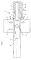
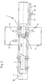
- the device shown schematically in FIGS. 1 and 2 and designated 1 serves for the transport of rod-shaped workpieces, for example a hollow profile 4, to a machining center 2 and for holding even during a machining process and essentially consists of a carriage which can be moved on a fixedly arranged rail 10 11, a large number of vices 21 and actuators for these in the form of servo devices 31, 41 and 51 which can be actuated by a pressure medium and are attached laterally next to the rail 10
- the servo device 41 is used to open one vise 21 each, and the two servo devices 51 can be used to release the connection between a vise 21 and the slide 11.
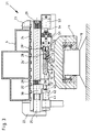
- a support plate 24 provided with grooves 24 ' is held to be displaceable to a limited extent in its axial direction, in the grooves 24' of which the clamping jaws 23 can be used alternately depending on the width of the workpiece to be clamped.
- the compression spring 29 acts on the support plate 24 via an intermediate piece 30.
- the attachment piece 30 is firmly connected to the support plate 24 and passes through the tube 25, into which longitudinal slots 25 'are incorporated.
- the clamping force of the compression spring 29 is thus transmitted to the support plate 24 and from this to the clamping jaws 23.
- the pressure medium consisting of a hydraulic cylinder 42 with pistons inserted in these pistons is to be supplied so that the piston rod 43 on the intermediate piece 30, to which a roller 30 'is attached can act.
- the vices 21 are detachably connected to the slide 11 by a clamp connection.
- a guide rail 12 which has wedge surfaces 13 and 13 ′, is fastened to it by means of screws 14, and a clamping piece 26 is attached to the pipe 25, which carries a further clamping piece 27 that can be pivoted about a bolt 28. Due to the force of a compression spring 29 'acting on the clamping piece 27 and supported on the clamping piece 26, the clamping piece 27 with the clamping surface 27' is pressed against the clamping piece 13, so that the vice 23 is carried along by the slide 11 when the slide 11 is moved.
- the clamping connection between the clamping piece 21 and the slide 11 is released by means of the servo device 51 designed as a collet 52.
- the piston rod 54 of a piston which is inserted into a cylinder 53 and can be acted upon by a pressure medium acts on the collet 52, by means of which the clamping lever 27 rotatably mounted on the bolt 28 is pivoted and can thus be released from the clamping piece 13.
- a workpiece 4 is to be machined in the machining center 2 by means of the tools inserted in a tool carrier 3, then first of all, by means of the servo device 31, which in the exemplary embodiment shown is designed as a plate 32 adjustable by a hydraulic cylinder 33 provided with a piston, are all separate to open vices 21 located outside the machining center 2.
- the servo device 31 acts on the intermediate pieces 30, so that the clamping jaws 23 are displaced to the right against the force of the spring 29 and the workpiece 4 can be inserted.
- the jaws 23 are on the Align the width of the workpiece 4.
- the clamping jaws 23 are pressed against the workpiece 4 by the force of the compression spring 29.
- the slide 11 is then fed to the tool carrier 3 in a controlled manner and the workpiece 4 is, for example, as shown in FIG. 2, divided into two tool segments 4 'and 4' '.
- the workpiece segments 4 'and 4' 'must be separated. This is accomplished in such a way that with the help of the servo devices 41 and / or 51 arranged opposite one another in the machining center 2 and a controlled method of the slide 11, in which the connections between a vice 21 and the respective workpiece segment 4 'or 4 '' and between the vice 21 and the slide 11 are solved, the vices 21 are positioned accordingly in relation to the workpiece segments 4 'and 4' '.
- the two servo devices 51 are to be arranged at such a distance from one another that at least the vices 21 acting on one of the workpiece segments 4 ', 4' 'can be actuated by the servo devices 51.
Landscapes
- Engineering & Computer Science (AREA)
- Mechanical Engineering (AREA)
- Jigs For Machine Tools (AREA)
- Feeding Of Workpieces (AREA)
- Supplying Of Containers To The Packaging Station (AREA)
- Electrical Discharge Machining, Electrochemical Machining, And Combined Machining (AREA)
Claims (8)
- Dispositif de transport et de maintien (1) pour des pièces en forme de barres (4), notamment pour des profilés creux qui peuvent être apportés à un centre d'usinage (2) et doivent être usinés dans ce dernier, comprenant un chariot (11) mobile sur un rail porteur fixe (10) et une pluralité d'étaux (21) disposés avec possibilité de réglage sur le rail porteur, dans lesquels la pièce (4) est maintenue au moyen de mors de serrage rapprochables (22, 23), et comprenant des mécanismes d'actionnement (31, 41, 51) pour ouvrir les mors de serrage (22, 23) ainsi que pour supprimer l'assemblage entre le chariot (11) et les étaux (21),
dans lequel les mécanismes d'actionnement (31, 41, 51) sont disposés sur le côté du rail porteur (10). - Dispositif de transport et de maintien selon la revendication 1, caractérisé en ce que le chariot (11) est pourvu d'une glissière de guidage (12) munie de faces obliques (13), sur laquelle les étaux (21) peuvent être bloqués au moyen de pièces de serrage (26, 27).
- Dispositif de transport et de maintien selon la revendication 2, caractérisé en ce que, afin de supprimer l'assemblage par serrage, il est prévu un servomécanisme (51) sous la forme d'une pince de serrage (52) pouvant être actionnée par un fluide sous pression et agissant sur un mors de serrage (27), pince qui est disposée perpendiculairement au rail porteur (10) sur le côté de ce dernier.
- Dispositif de transport et de maintien selon une des revendications 1 à 3, caractérisé en ce que les étaux (21) sont constitués chacun d'un mors de serrage fixe (22) et d'un mors de serrage (23) pouvant être réglé perpendiculairement au chariot (11) par la force d'un ressort (29).
- Dispositif de transport et de maintien selon la revendication 4, caractérisé en ce que les mors de serrage réglables (23) des étaux (21) peuvent être actionnés individuellement et/ou conjointement, à l'encontre de la force du ressort (29), par des servomécanismes (31, 41) pouvant être sollicités par un fluide sous pression.
- Dispositif de transport et de maintien selon une des revendications 1 à 5, caractérisé en ce qu'une pince de serrage (52) et un servomécanisme (41) pour l'actionnement des mors de serrage réglables des étaux (21) sont disposés en vis-à-vis, de préférence à l'intérieur du centre d'usinage (2).
- Dispositif de transport et de maintien selon une des revendications 1 à 6, caractérisé en ce que deux ou plus de deux pinces de serrage (52) sont disposées sur le côté du rail porteur (10), à distance latérale les unes des autres et, de préférence, avec possibilité de déplacement relatif.
- Dispositif de transport et de maintien selon une des revendications 1 à 7, caractérisé en ce que, afin de mettre en place une pièce (4) dans les étaux (21) disposés sur le chariot (11), il est prévu un servomécanisme (31), qui est disposé à côté du rail porteur (10) en dehors du centre d'usinage (2) et au moyen duquel les étaux (21) peuvent être conjointement actionnés.
Applications Claiming Priority (2)
| Application Number | Priority Date | Filing Date | Title |
|---|---|---|---|
| DE9303271U | 1993-03-06 | ||
| DE9303271U DE9303271U1 (de) | 1993-03-06 | 1993-03-06 | Transport- und Haltevorrichtung |
Publications (2)
| Publication Number | Publication Date |
|---|---|
| EP0623420A1 EP0623420A1 (fr) | 1994-11-09 |
| EP0623420B1 true EP0623420B1 (fr) | 1997-12-29 |
Family
ID=6890264
Family Applications (1)
| Application Number | Title | Priority Date | Filing Date |
|---|---|---|---|
| EP94102023A Expired - Lifetime EP0623420B1 (fr) | 1993-03-06 | 1994-02-10 | Dispositif de transport et de fixation |
Country Status (3)
| Country | Link |
|---|---|
| EP (1) | EP0623420B1 (fr) |
| AT (1) | ATE161457T1 (fr) |
| DE (2) | DE9303271U1 (fr) |
Cited By (2)
| Publication number | Priority date | Publication date | Assignee | Title |
|---|---|---|---|---|
| KR101450510B1 (ko) * | 2014-07-25 | 2014-10-15 | (주)한도기공 | 이동식 자동 결합 및 분리 장치 |
| CN106623666A (zh) * | 2017-01-12 | 2017-05-10 | 佛山市顺德区中兴盛自动化机械设备有限公司 | 一种应用于抽屉隐藏滑轨板的传送加工结构 |
Families Citing this family (5)
| Publication number | Priority date | Publication date | Assignee | Title |
|---|---|---|---|---|
| DE4409895A1 (de) * | 1994-03-23 | 1995-09-28 | Stegherr Maschinenbau Gmbh & C | Spannvorrichtung |
| DE19735069A1 (de) * | 1997-08-13 | 1999-02-18 | Baljer & Zembrod | Aufspann- und Zustellvorrichtung für die selbsttätige spanabhebende Bearbeitung von langen Werkstücken |
| PT1040891E (pt) * | 1999-03-17 | 2003-12-31 | Me C Al S N C Di Meschini Rose | Centro de trabalho que tem uma pluralidade de mordentes para apertar uma peca de obra |
| CN106180381A (zh) * | 2016-07-26 | 2016-12-07 | 滁州达世汽车配件有限公司 | 用于汽车冲压件的级进模 |
| US11999025B2 (en) | 2020-04-08 | 2024-06-04 | Peddinghaus Corporation | System and method for processing a workpiece |
Family Cites Families (4)
| Publication number | Priority date | Publication date | Assignee | Title |
|---|---|---|---|---|
| DE3406367C2 (de) * | 1984-02-22 | 1996-03-14 | Pries Horstmann & Co Maschinen | Vorrichtung zum Transportieren bzw. Handaben von auf einer Rollenbahn abgestützten plattenförmigen Werkstücken |
| ATE72344T1 (de) * | 1985-03-22 | 1992-02-15 | Oxytechnik Ges Systemtech | Einrichtung zur festlegung von schneidpositionen fuer profile,wie wulstprofile,i-profile und aehnliche stabfoermige werkstuecke. |
| DE3606182A1 (de) * | 1986-02-26 | 1987-09-03 | Bartholomaeus Huber | Werkzeugmaschine zum ablaengen und lochen von profilleisten |
| EP0562216A1 (fr) * | 1992-03-25 | 1993-09-29 | Fensterfabrik Albisrieden Ag | Machine-outil |
-
1993
- 1993-03-06 DE DE9303271U patent/DE9303271U1/de not_active Expired - Lifetime
-
1994
- 1994-02-10 AT AT94102023T patent/ATE161457T1/de not_active IP Right Cessation
- 1994-02-10 EP EP94102023A patent/EP0623420B1/fr not_active Expired - Lifetime
- 1994-02-10 DE DE59404855T patent/DE59404855D1/de not_active Expired - Fee Related
Cited By (2)
| Publication number | Priority date | Publication date | Assignee | Title |
|---|---|---|---|---|
| KR101450510B1 (ko) * | 2014-07-25 | 2014-10-15 | (주)한도기공 | 이동식 자동 결합 및 분리 장치 |
| CN106623666A (zh) * | 2017-01-12 | 2017-05-10 | 佛山市顺德区中兴盛自动化机械设备有限公司 | 一种应用于抽屉隐藏滑轨板的传送加工结构 |
Also Published As
| Publication number | Publication date |
|---|---|
| EP0623420A1 (fr) | 1994-11-09 |
| ATE161457T1 (de) | 1998-01-15 |
| DE59404855D1 (de) | 1998-02-05 |
| DE9303271U1 (de) | 1993-05-19 |
Similar Documents
| Publication | Publication Date | Title |
|---|---|---|
| EP1281491B1 (fr) | Dispositif et procédé pour travailler des pièces à usiner en bois, plastique ou similaires | |
| EP0922547B1 (fr) | Dispositif pour la fabrication de châssis de fenêtres | |
| EP3639971B1 (fr) | Procédé de traitement des pièces longues en bois, en matière plastique et analogue, ainsi que machine permettant de mettre en oeuvre ledit procédé | |
| DE60205939T2 (de) | Bearbeitungsmaschine für langgestreckte profile | |
| EP1600254B1 (fr) | Unité d'avance pour machine à usiner des pièces et méthode pour usiner ces pièces | |
| DE19919647C2 (de) | Werkzeugmaschine mit einem Manipulator | |
| DE19516263A1 (de) | CNC-gesteuerte Holzbearbeitungsanlage, insbesondere für lange Werkstücke wie Balken | |
| EP2165811A2 (fr) | Machine et procédé de traitement de pièces usinées en bois, en matière synthétique et analogue | |
| DE3346467A1 (de) | Werkzeugmaschine mit werkzeugwechselvorrichtung | |
| EP0623420A1 (fr) | Dispositif de transport et de fixation | |
| EP0787560B1 (fr) | Dispositif d'usinage des barres, des profilés et similaire | |
| CH680992A5 (fr) | ||
| EP0796701A1 (fr) | Etau | |
| DE3406367A1 (de) | Vorrichtung zum transportieren und bearbeiten von plattenfoermigen werkstuecken | |
| EP0507040B1 (fr) | Dispositif pour la saisie et l'abloquage de pièces à usiner | |
| DE10033705C2 (de) | Vorrichtung zum Bearbeiten von langgestreckten Werkstücken, insbesondere von Fenster- und Türeneinzelteilen | |
| EP0614728B1 (fr) | Etan | |
| DE602004001523T2 (de) | Werkzeugmaschine | |
| DE4018323C2 (de) | Einrichtung zum paarweisen Bearbeiten von Werkstücken aus Holz oder Kunststoff,insbesondere von Rahmenteilen für Fenster, Türen oder dgl. | |
| DE9315813U1 (de) | Langbettmaschine zur Bearbeitung von Profilen | |
| DE1912394C3 (de) | Schweißvorrichtung für das Verschweißen des längsgerichteten Schweißspaltes schlitzrohrartig geformter Hohlkörper, insbesondere konischer Masten | |
| DE3042716C2 (de) | Werkstückpositioniervorrichtung | |
| DE19703240B4 (de) | Vorrichtung zum Handhaben und Bearbeiten von vorzugsweise plattenförmigen Werkstücken | |
| DE10021028C2 (de) | Biegemaschine für langprofilförmige Werkstücke, insbesondere für Rohre | |
| DE102020002319A1 (de) | Spanneinrichtung für Werkstücke aus Holz, Kunststoff, Aluminium und dergleichen sowie Anlage mit einer solchen Spanneinrichtung |
Legal Events
| Date | Code | Title | Description |
|---|---|---|---|
| PUAI | Public reference made under article 153(3) epc to a published international application that has entered the european phase |
Free format text: ORIGINAL CODE: 0009012 |
|
| AK | Designated contracting states |
Kind code of ref document: A1 Designated state(s): AT CH DE FR GB IT LI NL SE |
|
| 17P | Request for examination filed |
Effective date: 19941018 |
|
| 17Q | First examination report despatched |
Effective date: 19960617 |
|
| GRAG | Despatch of communication of intention to grant |
Free format text: ORIGINAL CODE: EPIDOS AGRA |
|
| GRAG | Despatch of communication of intention to grant |
Free format text: ORIGINAL CODE: EPIDOS AGRA |
|
| GRAH | Despatch of communication of intention to grant a patent |
Free format text: ORIGINAL CODE: EPIDOS IGRA |
|
| GRAH | Despatch of communication of intention to grant a patent |
Free format text: ORIGINAL CODE: EPIDOS IGRA |
|
| GRAA | (expected) grant |
Free format text: ORIGINAL CODE: 0009210 |
|
| AK | Designated contracting states |
Kind code of ref document: B1 Designated state(s): AT CH DE FR GB IT LI NL SE |
|
| REF | Corresponds to: |
Ref document number: 161457 Country of ref document: AT Date of ref document: 19980115 Kind code of ref document: T |
|
| REG | Reference to a national code |
Ref country code: CH Ref legal event code: EP |
|
| REF | Corresponds to: |
Ref document number: 59404855 Country of ref document: DE Date of ref document: 19980205 |
|
| GBT | Gb: translation of ep patent filed (gb section 77(6)(a)/1977) |
Effective date: 19980127 |
|
| ITF | It: translation for a ep patent filed | ||
| PG25 | Lapsed in a contracting state [announced via postgrant information from national office to epo] |
Ref country code: SE Free format text: LAPSE BECAUSE OF FAILURE TO SUBMIT A TRANSLATION OF THE DESCRIPTION OR TO PAY THE FEE WITHIN THE PRESCRIBED TIME-LIMIT Effective date: 19980329 |
|
| ET | Fr: translation filed | ||
| PLBE | No opposition filed within time limit |
Free format text: ORIGINAL CODE: 0009261 |
|
| STAA | Information on the status of an ep patent application or granted ep patent |
Free format text: STATUS: NO OPPOSITION FILED WITHIN TIME LIMIT |
|
| 26N | No opposition filed | ||
| REG | Reference to a national code |
Ref country code: GB Ref legal event code: IF02 |
|
| PGFP | Annual fee paid to national office [announced via postgrant information from national office to epo] |
Ref country code: FR Payment date: 20060215 Year of fee payment: 13 Ref country code: NL Payment date: 20060215 Year of fee payment: 13 |
|
| PGFP | Annual fee paid to national office [announced via postgrant information from national office to epo] |
Ref country code: AT Payment date: 20060220 Year of fee payment: 13 |
|
| PGFP | Annual fee paid to national office [announced via postgrant information from national office to epo] |
Ref country code: GB Payment date: 20060221 Year of fee payment: 13 |
|
| PGFP | Annual fee paid to national office [announced via postgrant information from national office to epo] |
Ref country code: IT Payment date: 20060228 Year of fee payment: 13 |
|
| PGFP | Annual fee paid to national office [announced via postgrant information from national office to epo] |
Ref country code: DE Payment date: 20060405 Year of fee payment: 13 |
|
| PGFP | Annual fee paid to national office [announced via postgrant information from national office to epo] |
Ref country code: CH Payment date: 20060501 Year of fee payment: 13 |
|
| PG25 | Lapsed in a contracting state [announced via postgrant information from national office to epo] |
Ref country code: LI Free format text: LAPSE BECAUSE OF NON-PAYMENT OF DUE FEES Effective date: 20070228 Ref country code: CH Free format text: LAPSE BECAUSE OF NON-PAYMENT OF DUE FEES Effective date: 20070228 |
|
| REG | Reference to a national code |
Ref country code: CH Ref legal event code: PL |
|
| GBPC | Gb: european patent ceased through non-payment of renewal fee |
Effective date: 20070210 |
|
| NLV4 | Nl: lapsed or anulled due to non-payment of the annual fee |
Effective date: 20070901 |
|
| PG25 | Lapsed in a contracting state [announced via postgrant information from national office to epo] |
Ref country code: AT Free format text: LAPSE BECAUSE OF NON-PAYMENT OF DUE FEES Effective date: 20070210 |
|
| REG | Reference to a national code |
Ref country code: FR Ref legal event code: ST Effective date: 20071030 |
|
| PG25 | Lapsed in a contracting state [announced via postgrant information from national office to epo] |
Ref country code: NL Free format text: LAPSE BECAUSE OF NON-PAYMENT OF DUE FEES Effective date: 20070901 Ref country code: DE Free format text: LAPSE BECAUSE OF NON-PAYMENT OF DUE FEES Effective date: 20070901 |
|
| PG25 | Lapsed in a contracting state [announced via postgrant information from national office to epo] |
Ref country code: GB Free format text: LAPSE BECAUSE OF NON-PAYMENT OF DUE FEES Effective date: 20070210 Ref country code: FR Free format text: LAPSE BECAUSE OF NON-PAYMENT OF DUE FEES Effective date: 20070228 |
|
| PG25 | Lapsed in a contracting state [announced via postgrant information from national office to epo] |
Ref country code: IT Free format text: LAPSE BECAUSE OF NON-PAYMENT OF DUE FEES Effective date: 20070210 |