EP0623441A2 - Calandre à usage multiple - Google Patents
Calandre à usage multiple Download PDFInfo
- Publication number
- EP0623441A2 EP0623441A2 EP94104466A EP94104466A EP0623441A2 EP 0623441 A2 EP0623441 A2 EP 0623441A2 EP 94104466 A EP94104466 A EP 94104466A EP 94104466 A EP94104466 A EP 94104466A EP 0623441 A2 EP0623441 A2 EP 0623441A2
- Authority
- EP
- European Patent Office
- Prior art keywords
- roller
- displaceable
- calender
- displacement
- rollers
- Prior art date
- Legal status (The legal status is an assumption and is not a legal conclusion. Google has not performed a legal analysis and makes no representation as to the accuracy of the status listed.)
- Granted
Links
Images





Classifications
-
- B—PERFORMING OPERATIONS; TRANSPORTING
- B29—WORKING OF PLASTICS; WORKING OF SUBSTANCES IN A PLASTIC STATE IN GENERAL
- B29C—SHAPING OR JOINING OF PLASTICS; SHAPING OF MATERIAL IN A PLASTIC STATE, NOT OTHERWISE PROVIDED FOR; AFTER-TREATMENT OF THE SHAPED PRODUCTS, e.g. REPAIRING
- B29C43/00—Compression moulding, i.e. applying external pressure to flow the moulding material; Apparatus therefor
- B29C43/22—Compression moulding, i.e. applying external pressure to flow the moulding material; Apparatus therefor of articles of indefinite length
- B29C43/24—Calendering
-
- B—PERFORMING OPERATIONS; TRANSPORTING
- B29—WORKING OF PLASTICS; WORKING OF SUBSTANCES IN A PLASTIC STATE IN GENERAL
- B29C—SHAPING OR JOINING OF PLASTICS; SHAPING OF MATERIAL IN A PLASTIC STATE, NOT OTHERWISE PROVIDED FOR; AFTER-TREATMENT OF THE SHAPED PRODUCTS, e.g. REPAIRING
- B29C43/00—Compression moulding, i.e. applying external pressure to flow the moulding material; Apparatus therefor
- B29C43/22—Compression moulding, i.e. applying external pressure to flow the moulding material; Apparatus therefor of articles of indefinite length
- B29C43/28—Compression moulding, i.e. applying external pressure to flow the moulding material; Apparatus therefor of articles of indefinite length incorporating preformed parts or layers, e.g. compression moulding around inserts or for coating articles
Definitions
- the invention relates to a calender, in the calender stands one above the other two outer rollers and at least two inner rollers arranged between the two outer rollers are offset from one another, of which the two outer rollers are interlocked by adjusting means and displaceable by further adjusting means, and of which the an inner roller is fixedly mounted in the calender stands, while the other inner roller is displaceable by adjusting means for adjusting the nip width, the bearing housing of the displaceable inner roller being displaceable in elongated holes in the guides of the calender stand and wherein the displaceable, displaceable on the bearing housings of the outer Adjusting means acting on rollers act in directions perpendicular to each other.
- Such a calender is known from DE-PS 19 25 261 in a simplified embodiment in which the roller axes are arranged one above the other in a vertical plane.
- This known calender is used to cover a fabric with a rubber layer on both sides.
- one of the two inner rollers is included their bearings are firmly mounted in the calender stands, while the others are mounted with their associated outer roller in large and very heavy backdrops, which are motor-displaceably mounted in the calender stands.
- a further setting is slidably supported by motor forces, in which the outer roll assigned to the slidable inner roll is mounted.
- the production of this calender is very expensive and complex due to the two scenes.
- the invention avoids the disadvantages of the prior art. It is the object of the invention to provide, with simple means and in a simple manner, a universally applicable calender which is also suitable and determined for covering a material web, for example a fabric, on both sides with a rubber layer of small to large thickness, but by the elimination of the big scenes is cheaper to buy, lighter in weight and easier to use.
- the invention consists in the parallel arrangement of the displacement direction of the displaceable middle roller to the displacement direction of its associated displaceable and lockable outer roller and in the possibility of displacement of this outer roller beyond the possibility of displacement by the path and direction of the movable inner roller by at least one for coating the web required distance of the inner adjustable roller from the inner fixed roller.
- This calender can carry out the necessary roll adjustments without the heavy, two of the four rolls-bearing coulters even with products of considerable thickness, the whole calender can be considerably reduced in weight and in its acquisition costs by eliminating the coulters and by making stands lighter .
- this calender it can be used as a multi-purpose calender, that the calender is used both for calendering a web-like product in three nips and for doubling two webs, as well as for coating and laminating a fed web on one or both sides, as well as the friction of fabrics can be used, but is also suitable for the production of films and webs.
- a simple structure of this calender can be achieved in that in the calender stand arranged guides for the support of the bearing housing of the outer roller, which is adjacent to the displaceable inner roller, perpendicular to the guide of the displaceable inner roller, that the direction of displacement of this outer roller for its entanglement runs parallel to the guide of the displaceable inner roller, wherein the guides are arranged at an acute angle with respect to the horizontal and the vertical, and that the displacement possibility, which runs parallel to the guidance of the inner displaceable roller, is designed further than necessary for the entanglement, namely also for an additional roller displacement parallel to itself, and in this way far that the distance required for coating the web of the inner adjustable roller from the inner fixed roller are adjustable.
- an additional stroke distance must be taken into account for the emergency opening of the roller gap in the case of the adjustable inner roller.
- This calender can be implemented in several embodiments.
- a possible embodiment consists in that the bearing housing of the interlocking and displaceable roller can be displaced in guides of supports designed in the manner of an elongated hole, which in turn can be displaced in guides designed in the manner of an elongated hole, the guides in the supports being perpendicular to the guides in the calender stands.
- Another embodiment requiring less installation space is that the adjustment devices for the bearing housings of the adjacent outer roll acting parallel to the guides of the inner displaceable roller are fastened in the calender stands and clamp the bearing housings between them.
- a control device is provided with which the two adjacent bearing housings of the rolls, which can be displaced in their parallel guides, can be moved simultaneously and in parallel, and the individual working positions the rollers are reproducible.
- the guides in the supports are longer than the guides in the calender stands running parallel to them.
- the displaceable inner roller must be able to be moved so far that its guides are longer in practice.
- the axis of the movable middle roller is adjustable in an inclined plane so that in its end position it lies in the vertical plane passing through the axis of the fixed middle roller, while the axes of the outer rollers and the adjacent middle rollers are each arranged in an inclined plane which extends at an acute angle to the vertical.
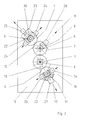
- the drawing Fig.1 shows a calender, in whose calender stands 5 two outer rolls 1, 4 and two inner rolls 2, 3, arranged in the middle between the two outer rolls 1, 4, one above the other, are offset from one another, of which the two outer Rollers 1.4 can be interlocked by adjusting means 24, 26 and can be displaced by further adjusting means 25, 27.
- One inner roller 3 is fixedly mounted in the calender stands 5, while the other inner roller 2 is displaceable by adjusting means 28.
- the bearing housing 6 of the displaceable inner roller 2 are displaceable in slots 8 in the form of guides 8 of the calender stand 5 and the bearing housings 6 of the outer interlockable and displaceable rollers 1.4 are displaceable in the form of slots 7.10 of supports 22, which in turn are in the form of slots in the form of guides 23 are displaceable in the calender stands 5.
- the guides 23 of the supports 22 arranged in the two stands 5 of the calender run perpendicular to the guides 7, 10 within the supports 22.
- the guides 7, 8, 23 are arranged at an acute angle with respect to the horizontal and the vertical.
- the parallel to the guide 8 of the inner displaceable roller 2, arranged on the carriers 22 guides 7.36 are so long that the distance required for coating the web 9 or 18 of the inner adjustable roller 2 from the inner fixed roller 3 and Entanglement are adjustable.
- the slot-like guides 7 in the carriers 22 and 8 in the calender stands for the bearing housing 6 of this one pair of displaceable adjacent rollers 1, 2 run parallel to one another at an acute angle with respect to the horizontal and the vertical.
- the guidance is so long that the distance between the inner adjustable roller 2 and the inner fixed roller 3 required for coating the web 9 or 18 is adjustable and the necessary roller gap is ensured in the event of an emergency switch.
- the bearing housing 6 of the outer roller 4 can be displaced in guides 10, the direction of which need not run parallel to the guides 7, 8.
- the axis of the middle roller 2 is adjustable in an inclined plane 11, namely up to a vertical plane running through the axis of the fixed roller 3.
- the axes of the outer rollers 1, 4 and the middle roller 2 adjacent to the outer roller 1 are each arranged in an oblique plane 12, 13 which extends at an acute angle to the vertical.
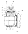
- the adjustment means 24 for the roller limitation and displacement of the roller 1 are fastened in the calender stands 5 and the bearing housings 6 can be displaced clamped between the adjustment means.
- the carriers 22 can be made smaller and lighter. This embodiment is shown constructively in FIGS. 3 and 4.
- the bearing housing 6 is clamped by two guide jaws 32, which are held and displaced under tension by displacement means 26.
- the bearing housing 6 is convex in the area of the engaging guide jaws, the guide jaws are concave with the same radius, so that they allow rotation of the bearing housing 6 within a certain angular range that is necessary for the roller limitation.
- the axis of these convex and concave surfaces 33 runs parallel to the axis of the adjusting device 25. This makes it possible to move the bearing housing by the adjusting means 25 without adjusting the adjusting means 26.
- a flat roller bearing 36 (this can also be designed as a flat sliding bearing) facilitates the displacement of the bearing housing 6 under the considerable loads caused by the nip pressure. This flat bearing 36 assumes the task of the guide 30 here.
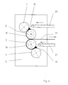
- this calender is suitable both for calendering a web-shaped product 14 in three nips, the material 15 to be processed being fed into the nip between rollers 1 and 2, and for duplicating two separately from Material webs 16 produced from material kneaders 15 and 19 to form a product 17 corresponding to FIG. 6.
- FIG. 7 Another example of application is shown in FIG. 7. Material webs 16 produced from material kneaders 15 and 19 are also found in the nip between rollers 2 and 3 a web 9 supplied from the outside is placed or laminated on, the product 20 is formed.
- FIG. 8 shows a further application example in which a material web produced by the material kneading unit 15 is placed or frictioned on one side onto the supplied material web 9.
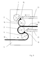
- FIG. 9 shows how a material web 18 fed under roller 4 is coated or clad on one side in the gap between rollers 3 and 4 by a material kneading device 19.
- a material kneading device 19 When the web passes through the calender further, its other side in the gap between the rollers 2 and 3 is covered with a web 16 produced by the material kneading unit 15.
- the invention thus achieves the universal usability of the calender in a very simple manner by a specific arrangement and dimensioning of some components of the calender, namely by the parallel arrangement of the displacement direction of the displaceable central roller to the displacement direction of the associated displaceable and lockable outer roller and by the parallel displacement possibility of this outer roller that goes beyond the interlocking possibility.
Landscapes
- Engineering & Computer Science (AREA)
- Mechanical Engineering (AREA)
- Casting Or Compression Moulding Of Plastics Or The Like (AREA)
- Treatment Of Fiber Materials (AREA)
- Coating Apparatus (AREA)
- Paper (AREA)
Applications Claiming Priority (2)
| Application Number | Priority Date | Filing Date | Title |
|---|---|---|---|
| DE4314653 | 1993-05-04 | ||
| DE4314653A DE4314653C2 (de) | 1993-05-04 | 1993-05-04 | Mehrzweckkalander |
Publications (3)
| Publication Number | Publication Date |
|---|---|
| EP0623441A2 true EP0623441A2 (fr) | 1994-11-09 |
| EP0623441A3 EP0623441A3 (fr) | 1994-12-28 |
| EP0623441B1 EP0623441B1 (fr) | 1996-09-18 |
Family
ID=6487099
Family Applications (1)
| Application Number | Title | Priority Date | Filing Date |
|---|---|---|---|
| EP94104466A Revoked EP0623441B1 (fr) | 1993-05-04 | 1994-03-22 | Calandre à usage multiple |
Country Status (5)
| Country | Link |
|---|---|
| US (1) | US5501145A (fr) |
| EP (1) | EP0623441B1 (fr) |
| CZ (1) | CZ107694A3 (fr) |
| DE (2) | DE4314653C2 (fr) |
| TW (1) | TW262454B (fr) |
Cited By (3)
| Publication number | Priority date | Publication date | Assignee | Title |
|---|---|---|---|---|
| US6064640A (en) * | 1995-12-15 | 2000-05-16 | Fujitsu Limited | Optical disk apparatus and medium carrier and medium turntable for optical disk apparatus |
| EP2363521A1 (fr) * | 2010-03-02 | 2011-09-07 | Andritz Küsters GmbH | Calandre de thermocollage |
| IT202300022080A1 (it) * | 2023-10-23 | 2025-04-23 | Barbieri Srl | Procedimento per la produzione di nastri trasportatori rinforzati |
Families Citing this family (17)
| Publication number | Priority date | Publication date | Assignee | Title |
|---|---|---|---|---|
| EP0861715B1 (fr) * | 1997-02-28 | 2004-04-14 | Chiba Machine Industry Corporation | Procédé et dispositif de formage des feuilles |
| DE19821820A1 (de) * | 1998-05-15 | 1999-11-18 | Voith Sulzer Papiertech Patent | Vorrichtung zur Oberflächenbehandlung einer laufenden Materialbahn, insbesondere aus Karton |
| DE19832066C2 (de) * | 1998-07-16 | 2000-06-08 | Voith Sulzer Papiertech Patent | Kalander für Bahnen aus Papier oder ähnlichem Material |
| US6861397B2 (en) * | 1999-06-23 | 2005-03-01 | The Dial Corporation | Compositions having enhanced deposition of a topically active compound on a surface |
| DE10133891C1 (de) * | 2001-07-12 | 2002-11-28 | Voith Paper Patent Gmbh | Kalander und Verfahren zum Anordnen von Walzen in einem Walzenstapel eines Kalanders |
| DE10133888C1 (de) * | 2001-07-12 | 2002-11-28 | Voith Paper Patent Gmbh | Verfahren zum Betreiben eines Kalanders und Kalander |
| DE10133889C1 (de) * | 2001-07-12 | 2002-11-28 | Voith Paper Patent Gmbh | Verfahren zum Betreiben eines Kalanders |
| DE10133890C1 (de) * | 2001-07-12 | 2002-12-05 | Voith Paper Patent Gmbh | Verfahren zum Betreiben eines Kalanders |
| DE10151905B4 (de) * | 2001-10-24 | 2005-10-06 | Schmidts, Rainer, Dipl.-Ing. | Einzugsvorrichtung für Folien o. dgl., insbesondere bei der Herstellung und Kontrolle von Kunstoffgranulat |
| FI5612U1 (fi) * | 2002-08-02 | 2002-11-27 | Metso Paper Inc | Porrastettu kalanteri |
| EP1520475A1 (fr) * | 2003-10-01 | 2005-04-06 | Doge Food Processing Machinery S.r.l. | Dispositif de laminage d'une feuille de pâte |
| DE102004033235A1 (de) * | 2004-07-08 | 2006-02-02 | Breyer Gmbh Maschinenfabrik | Verfahren zum Betreiben eines Vierwalzenglättwerkes |
| ITVA20040058A1 (it) * | 2004-11-26 | 2005-02-26 | Comerio Ercole Spa | Procedimento di fabbricazione per calandratura di un manufatto a nastro continuo costituito da tessuto accoppiato su entrambe le facce con pellicole di silicone |
| US9415577B1 (en) | 2013-10-03 | 2016-08-16 | The Boeing Company | Automated fabrication of composite fillers |
| US9855702B1 (en) * | 2013-10-03 | 2018-01-02 | The Boeing Company | Method and apparatus for making composite fillers |
| DE202014104438U1 (de) | 2014-09-17 | 2014-09-25 | Saueressig Gmbh + Co. Kg | Kalander zum Prägen, Glätten oder Laminieren von Materialbahnen oder Materialstücken |
| DE102015204265B4 (de) | 2015-03-10 | 2024-08-01 | Continental Reifen Deutschland Gmbh | Vorrichtung zum beidseitigen Belegen von Festigkeitsträgern mit Gummimischungsbahnen |
Family Cites Families (16)
| Publication number | Priority date | Publication date | Assignee | Title |
|---|---|---|---|---|
| US1793612A (en) * | 1927-07-09 | 1931-02-24 | Fisk Rubber Co | Calender construction |
| GB638290A (en) * | 1947-03-18 | 1950-06-07 | Dunlop Rubber Co | Improved calender |
| DE893260C (de) * | 1951-07-01 | 1953-10-15 | Erich Devermann | Kalander oder Walzwerk, insbesondere Ziehkalander |
| DE894767C (de) * | 1952-03-04 | 1953-10-26 | Eck & Soehne Joseph | Kalander in Z-foermiger Walzenanordnung |
| DE1053177B (de) * | 1957-03-02 | 1959-03-19 | J H Benecke Fa | Vierwalzenkalander |
| US2965920A (en) * | 1958-01-09 | 1960-12-27 | Farrel Birmingham Co Inc | Calender or like device |
| DE1218703B (de) * | 1963-05-07 | 1966-06-08 | Demag Ag | Mehrwalzenkalander |
| US3274308A (en) * | 1964-01-02 | 1966-09-20 | Du Pont | Calender bank size automatic control system |
| DE1925261C2 (de) * | 1969-05-17 | 1971-04-29 | Hermann Berstorff Maschb Gmbh | Mehrwalzenkalander,insbesondere Vierwalzenkalander,zum beidseitigen Belegen eines Gewebes mit einer Kautschukschicht |
| US3635627A (en) * | 1969-09-05 | 1972-01-18 | Franklin E Palmer | Calender sheeting thickness correction control system |
| US4306927A (en) * | 1978-01-26 | 1981-12-22 | The Celotex Corporation | Process for producing a laminate of metal with thermoplastic material |
| US4348952A (en) * | 1981-01-19 | 1982-09-14 | Usm Corporation | Cross axis mechanism |
| AT371767B (de) * | 1981-09-14 | 1983-07-25 | Semperit Ag | Vorrichtung zur beseitigung von lufteinschluessen zwischen einer kalanderwalzenoberflaeche und einer kalandrierten gummi- oder kunststoffplatte |
| JPS6051922B2 (ja) * | 1982-03-11 | 1985-11-16 | 三菱重工業株式会社 | ロ−ルクロス圧延方法 |
| DE3229477A1 (de) * | 1982-08-06 | 1984-02-09 | Battenfeld-EKK Extrusionstechnik GmbH, 4630 Bochum | Kalander insbesondere zur herstellung von kunststoffolien |
| US4516491A (en) * | 1983-09-30 | 1985-05-14 | Usm Corporation | Roll cross-axis mechanism |
-
1993
- 1993-05-04 DE DE4314653A patent/DE4314653C2/de not_active Expired - Fee Related
-
1994
- 1994-03-22 DE DE59400664T patent/DE59400664D1/de not_active Expired - Fee Related
- 1994-03-22 EP EP94104466A patent/EP0623441B1/fr not_active Revoked
- 1994-04-29 US US08/235,288 patent/US5501145A/en not_active Expired - Fee Related
- 1994-05-03 CZ CZ941076A patent/CZ107694A3/cs unknown
-
1995
- 1995-04-01 TW TW083102875A patent/TW262454B/zh active
Cited By (4)
| Publication number | Priority date | Publication date | Assignee | Title |
|---|---|---|---|---|
| US6064640A (en) * | 1995-12-15 | 2000-05-16 | Fujitsu Limited | Optical disk apparatus and medium carrier and medium turntable for optical disk apparatus |
| EP2363521A1 (fr) * | 2010-03-02 | 2011-09-07 | Andritz Küsters GmbH | Calandre de thermocollage |
| IT202300022080A1 (it) * | 2023-10-23 | 2025-04-23 | Barbieri Srl | Procedimento per la produzione di nastri trasportatori rinforzati |
| WO2025088447A1 (fr) * | 2023-10-23 | 2025-05-01 | Barbieri Srl | Procédé de production de bandes transporteuses renforcées |
Also Published As
| Publication number | Publication date |
|---|---|
| DE4314653A1 (de) | 1994-11-10 |
| DE4314653C2 (de) | 1997-01-30 |
| DE59400664D1 (de) | 1996-10-24 |
| EP0623441A3 (fr) | 1994-12-28 |
| EP0623441B1 (fr) | 1996-09-18 |
| CZ107694A3 (en) | 1994-11-16 |
| TW262454B (fr) | 1995-11-11 |
| US5501145A (en) | 1996-03-26 |
Similar Documents
| Publication | Publication Date | Title |
|---|---|---|
| EP0623441B1 (fr) | Calandre à usage multiple | |
| DE2139159A1 (de) | Vorrichtung zum breitstrecken von warenbahnen, insbesondere von papierbahnen | |
| DE2320369A1 (de) | Vorrichtung zum feststellen von dickeunterschieden in stapelfaserbaendern | |
| CH645958A5 (de) | Einrichtung mit einer druckbehandlungs- oder transportwalze. | |
| DE2940360A1 (de) | Einzelfalzwerk | |
| DE4035986A1 (de) | Kalander fuer den on-line-anschluss an eine papiermaschine | |
| DE3119677A1 (de) | "maschinensuperkalander fuer papier oder dergleichen" | |
| DE2549726A1 (de) | Siebpartie einer maschine zum herstellen einer faserbahn | |
| DE2643346C3 (de) | Presse zur Ausübung einer Flächenpressung mit umlaufenden Bändern und Steuerung der Seitenlage derselben | |
| DE3119691A1 (de) | Maschinen-superkalander fuer papier | |
| DE19832066C2 (de) | Kalander für Bahnen aus Papier oder ähnlichem Material | |
| DE2848295C2 (de) | Kalander zur Herstellung von thermoplastischer Folien | |
| DE3808142A1 (de) | Lagereinrichtung | |
| DE1955265B2 (de) | Maschine zum Ausdrucken von Flüssigkeit aus Häuten, Leder o.dgl | |
| DE19832067A1 (de) | Kalander für Bahnen aus Papier oder ähnlichem Material | |
| DE19731422B4 (de) | Transporteinheit für einen Spannrahmen | |
| EP0959166B1 (fr) | Dispositif pour le traitement d'une étoffe textile | |
| EP0979896B1 (fr) | Calandre pour bandes de papier ou analoque | |
| DE3919403C1 (en) | Continuous strip guide frame - has rollers at entry and exit of frame, sepd. by further location frame | |
| DE2801558C2 (de) | Kalanderwalzenanordnung | |
| DE10127986A1 (de) | Umlenkvorrichtung für Fördergurte | |
| DE19720174B4 (de) | Kalander | |
| DE3417030A1 (de) | Spannmaschine | |
| DE19601844A1 (de) | Leitwalze für eine Bahn aus Papier oder einem ähnlichen Material | |
| DE202004004037U1 (de) | Vorrichtung zur Herstellung von Span- un Faserplatten |
Legal Events
| Date | Code | Title | Description |
|---|---|---|---|
| PUAI | Public reference made under article 153(3) epc to a published international application that has entered the european phase |
Free format text: ORIGINAL CODE: 0009012 |
|
| PUAL | Search report despatched |
Free format text: ORIGINAL CODE: 0009013 |
|
| AK | Designated contracting states |
Kind code of ref document: A2 Designated state(s): DE FR GB IT |
|
| AK | Designated contracting states |
Kind code of ref document: A3 Designated state(s): DE FR GB IT |
|
| RTI1 | Title (correction) | ||
| 17P | Request for examination filed |
Effective date: 19950126 |
|
| 17Q | First examination report despatched |
Effective date: 19951010 |
|
| GRAH | Despatch of communication of intention to grant a patent |
Free format text: ORIGINAL CODE: EPIDOS IGRA |
|
| GRAH | Despatch of communication of intention to grant a patent |
Free format text: ORIGINAL CODE: EPIDOS IGRA |
|
| GRAA | (expected) grant |
Free format text: ORIGINAL CODE: 0009210 |
|
| ITF | It: translation for a ep patent filed | ||
| AK | Designated contracting states |
Kind code of ref document: B1 Designated state(s): DE FR GB IT |
|
| REF | Corresponds to: |
Ref document number: 59400664 Country of ref document: DE Date of ref document: 19961024 |
|
| ET | Fr: translation filed | ||
| GBT | Gb: translation of ep patent filed (gb section 77(6)(a)/1977) |
Effective date: 19961205 |
|
| PLBQ | Unpublished change to opponent data |
Free format text: ORIGINAL CODE: EPIDOS OPPO |
|
| PLBI | Opposition filed |
Free format text: ORIGINAL CODE: 0009260 |
|
| PLBF | Reply of patent proprietor to notice(s) of opposition |
Free format text: ORIGINAL CODE: EPIDOS OBSO |
|
| 26 | Opposition filed |
Opponent name: COMERIO ERCOLE SPA Effective date: 19970617 |
|
| PLBF | Reply of patent proprietor to notice(s) of opposition |
Free format text: ORIGINAL CODE: EPIDOS OBSO |
|
| PGFP | Annual fee paid to national office [announced via postgrant information from national office to epo] |
Ref country code: GB Payment date: 19990224 Year of fee payment: 6 |
|
| PGFP | Annual fee paid to national office [announced via postgrant information from national office to epo] |
Ref country code: FR Payment date: 19990225 Year of fee payment: 6 |
|
| PGFP | Annual fee paid to national office [announced via postgrant information from national office to epo] |
Ref country code: DE Payment date: 19990301 Year of fee payment: 6 |
|
| PLBQ | Unpublished change to opponent data |
Free format text: ORIGINAL CODE: EPIDOS OPPO |
|
| PLAB | Opposition data, opponent's data or that of the opponent's representative modified |
Free format text: ORIGINAL CODE: 0009299OPPO |
|
| PLBQ | Unpublished change to opponent data |
Free format text: ORIGINAL CODE: EPIDOS OPPO |
|
| PLAB | Opposition data, opponent's data or that of the opponent's representative modified |
Free format text: ORIGINAL CODE: 0009299OPPO |
|
| R26 | Opposition filed (corrected) |
Opponent name: COMERIO ERCOLE SPA Effective date: 19970617 |
|
| R26 | Opposition filed (corrected) |
Opponent name: COMERIO ERCOLE SPA Effective date: 19970617 |
|
| PG25 | Lapsed in a contracting state [announced via postgrant information from national office to epo] |
Ref country code: GB Free format text: LAPSE BECAUSE OF NON-PAYMENT OF DUE FEES Effective date: 20000322 |
|
| GBPC | Gb: european patent ceased through non-payment of renewal fee |
Effective date: 20000322 |
|
| PLAB | Opposition data, opponent's data or that of the opponent's representative modified |
Free format text: ORIGINAL CODE: 0009299OPPO |
|
| PLBQ | Unpublished change to opponent data |
Free format text: ORIGINAL CODE: EPIDOS OPPO |
|
| PG25 | Lapsed in a contracting state [announced via postgrant information from national office to epo] |
Ref country code: FR Free format text: LAPSE BECAUSE OF NON-PAYMENT OF DUE FEES Effective date: 20001130 |
|
| REG | Reference to a national code |
Ref country code: FR Ref legal event code: ST |
|
| PG25 | Lapsed in a contracting state [announced via postgrant information from national office to epo] |
Ref country code: DE Free format text: LAPSE BECAUSE OF NON-PAYMENT OF DUE FEES Effective date: 20010103 |
|
| R26 | Opposition filed (corrected) |
Opponent name: COMERIO ERCOLE SPA Effective date: 19970617 |
|
| RDAH | Patent revoked |
Free format text: ORIGINAL CODE: EPIDOS REVO |
|
| RDAG | Patent revoked |
Free format text: ORIGINAL CODE: 0009271 |
|
| STAA | Information on the status of an ep patent application or granted ep patent |
Free format text: STATUS: PATENT REVOKED |
|
| 27W | Patent revoked |
Effective date: 20030413 |