EP0623516B1 - Dispositif pour amener des encarts à une machine d'emballage - Google Patents
Dispositif pour amener des encarts à une machine d'emballage Download PDFInfo
- Publication number
- EP0623516B1 EP0623516B1 EP94102300A EP94102300A EP0623516B1 EP 0623516 B1 EP0623516 B1 EP 0623516B1 EP 94102300 A EP94102300 A EP 94102300A EP 94102300 A EP94102300 A EP 94102300A EP 0623516 B1 EP0623516 B1 EP 0623516B1
- Authority
- EP
- European Patent Office
- Prior art keywords
- packing
- compartment
- conveyor
- strip
- conveyor belts
- Prior art date
- Legal status (The legal status is an assumption and is not a legal conclusion. Google has not performed a legal analysis and makes no representation as to the accuracy of the status listed.)
- Expired - Lifetime
Links
- 238000004806 packaging method and process Methods 0.000 title description 6
- 238000012856 packing Methods 0.000 claims description 76
- 230000001154 acute effect Effects 0.000 claims description 6
- 210000000080 chela (arthropods) Anatomy 0.000 claims 11
- 230000032258 transport Effects 0.000 description 9
- 238000003780 insertion Methods 0.000 description 2
- 230000037431 insertion Effects 0.000 description 2
- 238000005452 bending Methods 0.000 description 1
- 238000010516 chain-walking reaction Methods 0.000 description 1
- 238000000151 deposition Methods 0.000 description 1
- 230000000694 effects Effects 0.000 description 1
- 238000005516 engineering process Methods 0.000 description 1
- 238000004904 shortening Methods 0.000 description 1
- 230000007704 transition Effects 0.000 description 1
Images

Classifications
-
- B—PERFORMING OPERATIONS; TRANSPORTING
- B65—CONVEYING; PACKING; STORING; HANDLING THIN OR FILAMENTARY MATERIAL
- B65B—MACHINES, APPARATUS OR DEVICES FOR, OR METHODS OF, PACKAGING ARTICLES OR MATERIALS; UNPACKING
- B65B61/00—Auxiliary devices, not otherwise provided for, for operating on sheets, blanks, webs, binding material, containers or packages
- B65B61/20—Auxiliary devices, not otherwise provided for, for operating on sheets, blanks, webs, binding material, containers or packages for adding cards, coupons or other inserts to package contents
Definitions
- the invention relates to a device for feeding packing inserts, such as brochures, instruction leaflets or the like, to packaged goods guided in a packaged goods chain of a packing machine and formed by objects, such as tubes, bottles, stacks of blister packs or the like, which together with the packing inserts in packing containers, in particular folding boxes, which are guided in a packaging container chain of the packaging machine, with a packaging insert conveyor, which transports the packaging inserts folded into a strip between two endless conveyor belts, which lie alongside one another along their transport route, to a discharge opening at which the conveyor belts arrive Pulleys are diverted in opposite directions, and with an endlessly rotating chain of clamping pliers, each with one of the packing insert strips at one end of the strip and gripping clamps feeding it to the packaged goods chain, which run in a substantially vertical take-over plane when the packing insert strips are taken over, the packing insert strips taking over with them their strip surface are also aligned parallel to the transfer plane and their length is essentially transverse to the running direction of the clamping pliers.
- the clamping tongs take over the package insert strips directly from the package insert conveyor at its discharge opening.
- the conveyor belts run in front of and in the discharge opening within the takeover level, the transport speed of the conveyor belts being somewhat greater than that of the clamping tongs, so that the packing insert strips are inserted from behind into the clamping tongs in the transport direction, which accordingly have a pliers mouth with a rearward opening .
- the takeover technology requires very precise coordination between the conveyor speeds of the conveyor belts and the chain of clamps and between the distances with which the package inserts and the clamps follow one another in the takeover area.
- the necessity to let the conveyor belts run in front of and at the delivery mouth in the takeover level has a constructive disadvantageous effect on the length and guidance of the transport route formed by the conveyor belts.
- the discharge mouth forming between them Deflection pulleys arranged on both sides of the transfer level.
- the take-over level must therefore have a distance of at least the diameter of the deflecting roller lying on this side of the take-over level compared to the level in which the packing inserts on the packaged goods chain are inserted into the packing containers, which is associated with considerable constructive effort with regard to the course of the clamping pliers chain is.
- the invention has for its object to improve the takeover of the package inserts from the conveyor belts in the clamping tongs in terms of operational safety in a device of the type mentioned and to simplify the design effort.
- a collecting pocket is provided for each one of the package insert strips leaving the delivery mouth of the package insert conveyor, which keeps the package insert strip aligned in the position specified for the takeover by the clamping tongs and from which the package insert strip in the direction of its length with at least the strip end to be gripped by the clamping pliers protrudes into the path of the clamping pliers, which receive the strip end with the opening of the pliers mouth facing forward in its running direction, that the collecting pocket for the exit of the packing insert strip seized by the clamping pliers is open in the running direction of the clamping pliers, and that above this pocket opening is the delivery mouth of the package insert conveyor, the deflecting rollers of its conveyor belts being arranged on the same side of the take-over level and one of these passing the by the clamping tongs hardships Package insert strips allow clearance.
- the packing insert strips are placed in the collecting bag provided according to the invention by the packing insert conveyor and then removed from the collecting bag by the clamping tongs.
- the packing insert conveyor As a result, there is a time margin between depositing and removing that is able to compensate for differences in the mutual timing of the package insert conveyor and the clamp chain.
- the rotational speeds of the transport change and the clamp chain no longer need to be matched to one another. It is only necessary that the collecting bag is re-equipped in good time with a packing insert strip from the delivery mouth of the packing insert conveyor before each clamping forceps passes by.
- the deflection rollers of the conveyor belts forming the delivery mouth are on the same side of the take-over level, there does not have to be a gap between the take-over level and the level in which the package insert strips are guided between the packaged goods chain and the pack container chain for insertion into the pack containers . Both levels can coincide, which greatly simplifies the guidance of the conveyor belts and the chain of clamps.
- the collecting bag is loaded with the packing insert strips from above from the discharge mouth. This offers the possibility of significantly shortening and simplifying the guidance of the conveyor belts between the folder for the packing inserts and the collecting bag and, moreover, to arrange the folder with the packing insert magazine ergonomically advantageously on the packaging machine, so that the magazine is simple and easily accessible.
- the collecting pocket is formed between two pocket walls connected at the lower edge by a pocket bottom, of which the front pocket wall lies opposite the dispensing mouth in the takeover plane and the rear pocket wall adjoins the dispensing mouth with its upper pocket edge.
- the front pocket wall extends with its upper edge to the height of the run of the clamp chain, which runs parallel to the packaged goods conveyor, so that the front pocket wall can also guide the packing insert strips when they have already been removed from the catch pocket by the clamps and from the lying in the upright orientation in front of the packaged goods is redirected.
- a very simple and reliable loading of the collecting bag results from the fact that the conveyor belts run obliquely in front of and in the discharge mouth from top to bottom at an acute angle with respect to the transfer plane. Then the packing insert strips at the transition from the dispensing mouth into the collecting bag no longer need to change their orientation to any significant extent and do not experience any significant bending.
- the deflection rollers for the conveyor belts with axes parallel to the transfer plane and to the bag bottom are arranged one above the other in such a way that their common tangential plane lying on the side of the collecting bag runs parallel to the transfer plane and at a distance from the front bag wall that enables the passage of the package insert strips.
- the lower guide roller with the conveyor belt guided by it engages through a cut-out opening in the rear pocket wall into the collecting pocket, the upper edge of the rear pocket wall is located below the part of the conveyor belt that runs onto the deflection roller.
- the packing insert strip can also lie in the collecting bag against the conveyor belt running around the deflection roller, which can generate a frictional force on the packing insert strip, which contributes to reliably bringing the packing insert strip in the collecting bag into the takeover position and in it until it is removed by the clamping pliers to back up.
- the rear pocket wall is expediently inclined at an acute angle with respect to the take-over plane, so that the collecting pocket widens in the direction of the upper edge of the rear pocket wall, this angle being smaller than the angle formed by the conveyor belts in the delivery mouth with the take-over plane.
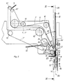
- the device shown in the drawing serves for feeding packing inserts in the form of brochures to a packaged goods chain of a packing machine, the packaged goods chain only indicated in FIG. 1 at 1 having receptacles for objects to be packed, such as tubes, bottles, stacks of blister packs or the like, which are also not shown.
- the packaged goods are inserted together with the packing inserts into packing containers, in particular folding boxes, which are guided in a packing container chain of the packing machine, which is also not shown in the drawing.
- the package inserts folded into strips 6 in the folder 5 are between two endless Conveyor belts 7 ', 7'', which run along their transport path to each other, transported to a discharge opening 8, at which the conveyor belts 7', 7 '' on deflection rollers 9 ', 9''are deflected in opposite directions, so that the form two delivery rollers 9 ', 9''with the deflected on them conveyor belts 7', 7 '' between them the delivery mouth 8, from which the packing insert strips 6 emerge.
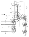
- a pair of the conveyor belts 7 ', 7'' is located on both sides of this boom 11.
- the strips 6 are placed in the folder 5 between the deflecting rollers 10'.
- clamping pliers 2 run around with the clamping pliers chain 3 and past opening cams 12 which are fixed along the chain guide and on which a pliers arm 13 which opens the clamping pliers runs with a roller 14.
- Each clamping pliers 2 consists of a pliers plate 15 forming a support for the packing insert strip 6 and the pliers arm 13 that can be pivoted about an axis 16.
- the forceps arm 13 carries in the area of the forceps plate 15 a clamping bracket 17, between which and the forceps plate 15 the insert strip 6 is clamped when the clamping forceps 2 is closed.
- the clamping bracket 17 In the open state, the clamping bracket 17 is lifted off the pliers plate 15 and, together with the latter, forms an open pliers mouth which enables the insertion of the package insert strip 6 and which is directed forward with its opening in the chain running direction (arrow 18).
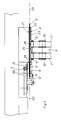
- the package insert strips 6 are 60 at one end of the strip captured by the clamping tongs 2 and fed to the packaged goods chain, the takeover of the packing insert strips 6 by the clamping tongs 2 taking place in an upward-running part of the clamping pliers chain 3 and in the further course of the chain the clamping tongs 2 and the packing insert strips 6 by 90 ° in the direction of the one entered in FIG. 3 Arrow 18 'are redirected in front of the packaged goods chain.
- the clamping pliers 2 run in an essentially vertical take-over plane 20, which is formed by the plane of the drawing in FIG. 3 and is indicated by dot-dash lines in the other figures.
- the packing insert strips 6 are also aligned with their strip surface parallel to the transfer plane when they are taken over, and their length is essentially transverse to the running direction 18 of the clamping pliers 2, that is to say essentially horizontally.
- This position of the package insert strips 6 is designated A in the drawing.
- the vertical position of the packing insert strips 6 in front of the packaged goods chain after its deflection is denoted by B.
- a collecting bag 21 is provided for the packing insert strips 6 leaving the delivery mouth 8 of the packing insert conveyor one after the other.
- the collecting bag takes up only one of the packing insert strips 6 and aligns it in the position specified for takeover by the clamp pliers 2 and secures it in this position.
- the packing insert strip 6 also protrudes from the collecting bag 21 in the direction of its length with at least the strip end 60 to be gripped by the clamping tongs 2 in the path of the clamping tongs 2, as can best be seen from FIGS. 3 and 4.
- the collecting bag 21 is for the exit of the packing insert strip 6 gripped by the clamping tongs 2
- the direction of rotation of the clamps 2 (arrow 18) is open at the top.
- the deflection rollers 9 ', 9''of the conveyor belts 7', 7 '' forming the delivery opening being arranged on the same side in FIG. 2 as the left of the transfer plane 20.
- the deflection rollers 9 ′, 9 ′′ keep a distance from the take-over level 20, which enables the packing insert strips 6 gripped by the clamping tongs 2 to run past the deflection rollers 9 ′, 9 ′′.
- the collecting pocket 21 is formed between two pocket walls 23, 24 connected at the lower edge by a pocket bottom 22.
- the front pocket wall 24 is practically opposite the dispensing mouth 8 in the takeover plane 20.
- the rear pocket wall 23 connects with its upper pocket edge 23 'approximately to the dispensing mouth 8, while the front pocket wall 24 with its upper edge 24' up to the level with the Packaged goods conveyor runs parallel runs (arrow 18 ') of the clamp chain 3 so that it also leads the packing insert strips 6 on part of the way on which the packing insert strips 6 are deflected in the direction of arrow 25 from the horizontal orientation A into the vertical orientation B. become.
- the conveyor belts 7 ', 7'' run in front of and in the delivery mouth 8 obliquely from top to bottom at an acute angle 26 against the transfer plane 20, so that the package insert strips 6 emerging in the delivery mouth 8 between the conveyor belts 7', 7 '' without noteworthy bend and deflection in the collecting bag 21.
- the deflection rollers 9 ', 9'' are arranged one above the other with axes parallel to the transfer plane 20 and to the pocket bottom 22 such that their axes are on the side of the collecting pocket 21 lying common tangential plane 27 runs parallel to the take-over plane 20 and forms with the front pocket wall 24 a gap area which is sufficiently wide for the passage of the package insert strips 6 when they are removed from the collecting pocket 21 by the clamping pliers 2.
- the upper edge 23 'of the rear pocket wall 23 is located below the part of the conveyor belt 7' which runs onto the deflecting roller 9 ', so that emerged from the discharge opening 8 and on the lower conveyor belt 7' in the region of its deflecting roller 9 'into the collecting pocket 21 sliding slip inserts 6 can not get caught on the upper edge 23 'of the rear pocket wall 23.
- the protrusion of the lower guide roller 9 'and the conveyor belt 7' running on it in the collecting bag 21 has the advantage that the folded and in its folds u. U.
- a control disk 30 is driven via a toothed belt 29, which has a control cam on which a rocker arm 31 runs, which carries a rod 32 with an articulated head 33 which actuates a rocker arm 35 rotatably mounted about an axis 34 which is a packing insert stop 36, which is provided next to the conveyor belts 7 ', 7' 'shortly before the discharge opening 8 and is adjustable in accordance with the oscillating movement of the rocker arm 35 in the path of the packing insert strips 6 projecting laterally between the conveyor belts 7', 7 ''.
- the package insert stop forms stops for the package insert strips 6, by means of which the package insert strips 6 are aligned between the conveyor belts 7 ′, 7 ′′ and stopped in their further transport until the package insert stopper 36 by swinging back into FIG. 2 36 'position indicated by dashed lines releases the packing insert strips 6 for delivery into the collection pocket 21.
Landscapes
- Engineering & Computer Science (AREA)
- Mechanical Engineering (AREA)
- Auxiliary Devices For And Details Of Packaging Control (AREA)
- Container Filling Or Packaging Operations (AREA)
Claims (8)
- Dispositif pour amener des documents joints à l'emballage, tels que des prospectus, des étiquettes annexées ou analogues, jusqu'à des produits à emballer envoyés selon une suite de produits à emballer, à une machine d'emballage et formés par des objets tels que des tubes, des bouteilles, des piles d'emballages thermoformées ou analogues, et qui sont insérés conjointement avec les documents joints à l'emballage dans des récipients d'emballage, notamment des boîtes pliantes, qui sont envoyés selon une suite de récipients d'emballage à la machine d'emballage, et comportant un convoyeur d'entraînement des documents joints à l'emballage, qui sont pliés sous la forme d'une bande (6), entre deux bandes convoyeuses sans fin (7', 7''), qui circulent sur leur trajet de déplacement en s'appliquant l'une contre l'autre, jusqu'à une embouchure de sortie (8), au niveau de laquelle les bandes convoyeuses (7', 7'') sont déviées au niveau de rouleaux de renvoi (9', 9'') dans des directions réciproquement opposées, et comportant une chaîne (3) de pinces de serrage, qui circule sans fin et comporte des pinces de serrage (2), qui saisissent respectivement l'une des bandes (6) de documents joints à l'emballage au niveau d'une extrémité (60) de la bande et l'introduisent dans la suite des produits à emballer et qui, lors du transfert des bandes (6) de documents joints à l'emballage, s'étendent dans un plan de transfert (20) essentiellement vertical, et dans lequel lors du transfert, les bandes (6) des documents joints à l'emballage sont également orientées de sorte que leur surface est également parallèle au plan de transfert (20) et que leur direction longitudinale est essentiellement transversale par rapport à la direction de déplacement des pinces de serrage (2), caractérisé en ce qu'il est prévu un logement de réception (21) pour respectivement une bande (6) de documents joints à l'emballage, qui quitte l'embouchure de sortie (8) du convoyeur de documents joints à l'emballage, logement de réception qui maintient la bande (6) de documents joints à l'emballage dans la position prédéterminée pour le transfert au moyen des pinces de serrage (2), et hors duquel la bande (6) de documents joints à l'emballage fait saillie, dans la direction de sa longueur, par au moins son extrémité (60), qui doit être saisie par les pinces de serrage (2), dans le trajet (2) des pinces de serrage, qui reçoivent l'extrémité (60) de la bande, l'ouverture des mâchoires de la pince étant dirigée vers l'avant, dans la direction de déplacement des pinces, qu'en outre, pour la sortie de la bande (6) de documents joints à l'emballage, saisie par les pinces de serrage (2), le logement de réception (21) est ouvert dans la direction de déplacement de pinces de serrage (2) et que l'embouchure de sortie (8) du convoyeur des documents joints à l'emballage est située au-dessus de cette ouverture du logement, les rouleaux de renvoi (9', 9'') des bandes de transport (7', 7'') de ce convoyeur étant disposés du même côté du plan de transfert (20) et étant situés par rapport à ce dernier, à une distance permettant le passage des bandes (6) de documents joints à l'emballage, guidées par les pinces de serrage (2).
- Dispositif selon la revendication 1, caractérisé en ce que le logement de réception (21) est formé entre deux parois de logement (23,24), qui sont reliées au niveau du bord inférieur par un fond (22) du logement et parmi lesquelles la paroi avant (24) du logement est située en vis-à-vis de l'embouchure de sortie (8) dans le plan de transfert (20) et la paroi arrière (23) du logement se raccorde, par son bord supérieur (23), à l'embouchure de sortie (8).
- Dispositif selon la revendication 2, caractérisé en ce que la paroi avant (24) du logement s'étend, par son bord supérieur (24'), jusqu'au niveau du brin de la chaîne à pinces de serrage (3), qui circule parallèlement au convoyeur véhiculant les produits à emballer.
- Dispositif selon l'une des revendications 1 à 3, caractérisé en ce que les bandes convoyeuses (7', 7'') s'étendent en amont de l'embouchure de sortie (8) et dans cette dernière, obliquement de haut en bas, en faisant un angle aigu (26) par rapport au plan de transfert (20).
- Dispositif selon l'une des revendications 2 à 4, caractérisé en ce que les rouleaux de renvoi (9', 9'') pour les bandes convoyeuses (7', 7'') sont disposés en superposition avec leurs axes parallèles au plan de transfert (20) et au fond (22) du logement de telle sorte que leur plan tangentiel commun (27), qui est situé du côté du logement de réception (21), est parallèle au plan de transfert (20) et s'étend à une distance de la paroi avant (24) du logement, qui permet le passage des bandes (6) de documents joints à l'emballage.
- Dispositif selon la revendication 5, caractérisé en ce que le rouleau de renvoi inférieur (9') s'engage, conjointement avec la bande convoyeuse (7') qu'il guide, dans une découpe (28) ouverte vers le haut, ménagée dans la paroi arrière (23) du logement, pour pénétrer dans le logement de réception (21), le bord supérieur (23') de la paroi arrière (23) du logement étant situé au-dessous de la partie de la bande convoyeuse (7'), qui circule sur le rouleau de renvoi (9').
- Dispositif selon l'une des revendications 2 à 6, caractérisé en ce que la paroi arrière (23) du logement est inclinée sous un angle aigu par rapport au plan de transfert (20) de telle sorte que le logement de réception (21) s'élargit en direction du bord supérieur (23') de la paroi arrière (23) du logement, cet angle étant inférieur à l'angle (26) formé par les bandes convoyeuses (7', 7'') dans l'embouchure de sortie (8), par rapport au plan de transfert (20).
- Dispositif selon l'une des revendications 1 à 7, caractérisé en ce qu'à côté des bandes convoyeuses (7', 7'') et légèrement en avant de l'embouchure de sortie (8) est prévu un dispositif (36) d'arrêt des documents joints à l'emballage, qui est déplaçable dans le trajet des bandes (6) de documents joints à l'emballage, qui font saillie latéralement entre les bandes convoyeuses (7', 7'') et forme alors une butée (36) qui aligne les bandes (6) de documents joints à l'emballage entre les bandes convoyeuses (7', 7'') et arrête la poursuite de leur entraînement.
Applications Claiming Priority (2)
| Application Number | Priority Date | Filing Date | Title |
|---|---|---|---|
| DE4314631 | 1993-05-04 | ||
| DE4314631A DE4314631C1 (de) | 1993-05-04 | 1993-05-04 | Vorrichtung zur Zuführung von Packbeilagen |
Publications (2)
| Publication Number | Publication Date |
|---|---|
| EP0623516A1 EP0623516A1 (fr) | 1994-11-09 |
| EP0623516B1 true EP0623516B1 (fr) | 1996-09-18 |
Family
ID=6487085
Family Applications (1)
| Application Number | Title | Priority Date | Filing Date |
|---|---|---|---|
| EP94102300A Expired - Lifetime EP0623516B1 (fr) | 1993-05-04 | 1994-02-16 | Dispositif pour amener des encarts à une machine d'emballage |
Country Status (3)
| Country | Link |
|---|---|
| US (1) | US5463840A (fr) |
| EP (1) | EP0623516B1 (fr) |
| DE (1) | DE4314631C1 (fr) |
Families Citing this family (6)
| Publication number | Priority date | Publication date | Assignee | Title |
|---|---|---|---|---|
| US5771657A (en) * | 1996-05-07 | 1998-06-30 | Merck Medco Managed Care, Inc. | Automatic prescription filling, sorting and packaging system |
| DE10223066A1 (de) * | 2002-05-24 | 2003-12-11 | Iwk Verpackungstechnik Gmbh | Verpackungsmaschine |
| US7995831B2 (en) * | 2003-01-30 | 2011-08-09 | Express Scripts, Inc. | Prescription bottle imaging system and method |
| US7313898B1 (en) | 2003-08-29 | 2008-01-01 | Express Scripts, Inc. | Container carrying system and method for use in an automated filling process |
| CN110077660B (zh) * | 2019-04-02 | 2021-04-06 | 山东恒富家居科技有限公司 | 床垫一体化成型生产设备 |
| ES3012082T3 (en) * | 2021-01-13 | 2025-04-08 | Ecolean Ab | Device for applying an article to a moving object |
Family Cites Families (10)
| Publication number | Priority date | Publication date | Assignee | Title |
|---|---|---|---|---|
| GB871349A (en) * | 1956-11-09 | 1961-06-28 | Rose Brothers Ltd | Improvements in the production of cartons each containing a coupon, card or the like, from carton blanks |
| US3797196A (en) * | 1972-12-04 | 1974-03-19 | Pitney Bowes Inc | Letter folder and envelope inserter |
| IT1089385B (it) * | 1977-11-03 | 1985-06-18 | Martelli Guglielmo | Dispositivo per l alimentazione di foglietti a macchine astucciatrici |
| DE3118209A1 (de) * | 1981-05-08 | 1983-01-20 | IWK Verpackungstechnik GmbH, 7513 Stutensee | Vorrichtung zum zufuehren von beilagen, die gemeinsam mit produkten in behaeltnisse eingeschoben werden |
| DE3331672A1 (de) * | 1983-09-02 | 1985-03-21 | Robert Bosch Gmbh, 7000 Stuttgart | Vorrichtung zum zufuehren von prospekten in einer kartoniermaschine |
| FR2623751B1 (fr) * | 1987-11-26 | 1991-04-19 | Smh Alcatel | Dispositif d'insertion de plis sous enveloppes |
| US4852334A (en) * | 1988-09-12 | 1989-08-01 | Pitney Bowes Inc. | Envelope opening apparatus |
| IT215564Z2 (it) * | 1989-01-30 | 1990-10-10 | Meccanizzazione Postale E Auto | Dispositivo per impilare di costa, in un contenitore o sistema fisso o mobile di accumulo, oggetti piatti singolarizzati, provenienti da un impianto convogliatore a nastro o simile. |
| DE4022162A1 (de) * | 1990-07-12 | 1992-01-16 | Licentia Gmbh | Vorrichtung und verfahren zum abstapeln von kleingut |
| US5235796A (en) * | 1992-03-19 | 1993-08-17 | Campbell-Hardage, Inc. | Method and apparatus for packaging articles |
-
1993
- 1993-05-04 DE DE4314631A patent/DE4314631C1/de not_active Expired - Fee Related
-
1994
- 1994-02-16 EP EP94102300A patent/EP0623516B1/fr not_active Expired - Lifetime
- 1994-04-18 US US08/229,324 patent/US5463840A/en not_active Expired - Fee Related
Also Published As
| Publication number | Publication date |
|---|---|
| US5463840A (en) | 1995-11-07 |
| EP0623516A1 (fr) | 1994-11-09 |
| DE4314631C1 (de) | 1994-04-28 |
Similar Documents
| Publication | Publication Date | Title |
|---|---|---|
| DE2500569C2 (de) | Vorrichtung zum Verpacken von Gegenständen in ein Hüllmaterial | |
| DE69402856T2 (de) | Vorrichtung zum füllen von briefumschlägen | |
| EP0380905B1 (fr) | Dispositif pour l'alimentation en sacs individuels | |
| EP0208081B1 (fr) | Procédé et dispositif d'ouverture pour imprimés pliés de manière excentrée | |
| CH665814A5 (de) | Verfahren und vorrichtung zum einfuellen von fuellgut in eine huelle. | |
| DE9006297U1 (de) | Einlegestation für Faltschachteln | |
| DE2125991A1 (de) | Verfahren und Vorrichtung zum Transport gestapelter flacher Gegenstände in Aufeinanderfolge zu einem Auffangen | |
| DE3786746T2 (de) | Apparat zum transportieren und öffnen eines getränketrägers. | |
| EP0854105B1 (fr) | Méthode et dispositif pour traiter des produits imprimes plats, comme des journaux, des magazines, et des parties de cela | |
| DE69026238T2 (de) | Einstecken der beilagen in zeitungen | |
| DE3715570C2 (fr) | ||
| DE4314631C1 (de) | Vorrichtung zur Zuführung von Packbeilagen | |
| DE1900450B1 (de) | Vorrichtung zum seitlichen Umhuellen einer Behaeltergruppe mittels eines Pappzuschnitts | |
| DE3514376A1 (de) | Verpackungsmaschine | |
| EP0139889A2 (fr) | Dispositif pour l'alimentation en brochures dans une machine d'encartonnage | |
| DE60108895T2 (de) | Maschine zum verpacken von gegenständen, insbesondere cds, dvds und dergleichen, in behältern | |
| DE3529657C2 (de) | Vorrichtung zum Verpacken von einen Tubenfalz aufweisenden Tuben | |
| DE3815557A1 (de) | Verbundmaschine zum automatischen verpacken von packgut in faltschachteln | |
| DE3118209C2 (fr) | ||
| DE1244042B (de) | Vorrichtung zum kontinuierlichen Herstellen von flachbeutelartigen Verpackungen | |
| AT404116B (de) | Einrichtung zur entnahme von säcken | |
| DE2507022C3 (de) | Sammelpackanlage für flache, rechteckige Gegenstände, insbesondere einzeln eingewickelte Schokoladentafeln oder -riegel | |
| EP1050463B1 (fr) | Machine de liage pour lier une pile d'objets | |
| EP2706031B1 (fr) | Dispositif de transmission d'unités de produit entre un convoyeur d'amenée et un convoyeur de sortie | |
| DE3248628A1 (de) | Beutel-verpackungsmaschine und verfahren zum zufuehren von beutelpaketen |
Legal Events
| Date | Code | Title | Description |
|---|---|---|---|
| PUAI | Public reference made under article 153(3) epc to a published international application that has entered the european phase |
Free format text: ORIGINAL CODE: 0009012 |
|
| 17P | Request for examination filed |
Effective date: 19940903 |
|
| AK | Designated contracting states |
Kind code of ref document: A1 Designated state(s): AT BE CH DE DK ES FR GB GR IE IT LI LU MC NL PT SE |
|
| RBV | Designated contracting states (corrected) |
Designated state(s): FR IT |
|
| REG | Reference to a national code |
Ref country code: DE Ref legal event code: 8566 |
|
| GRAG | Despatch of communication of intention to grant |
Free format text: ORIGINAL CODE: EPIDOS AGRA |
|
| GRAH | Despatch of communication of intention to grant a patent |
Free format text: ORIGINAL CODE: EPIDOS IGRA |
|
| 17Q | First examination report despatched |
Effective date: 19960312 |
|
| GRAH | Despatch of communication of intention to grant a patent |
Free format text: ORIGINAL CODE: EPIDOS IGRA |
|
| GRAA | (expected) grant |
Free format text: ORIGINAL CODE: 0009210 |
|
| AK | Designated contracting states |
Kind code of ref document: B1 Designated state(s): FR IT |
|
| ET | Fr: translation filed | ||
| ITF | It: translation for a ep patent filed | ||
| PGFP | Annual fee paid to national office [announced via postgrant information from national office to epo] |
Ref country code: FR Payment date: 19970220 Year of fee payment: 4 |
|
| PLBE | No opposition filed within time limit |
Free format text: ORIGINAL CODE: 0009261 |
|
| STAA | Information on the status of an ep patent application or granted ep patent |
Free format text: STATUS: NO OPPOSITION FILED WITHIN TIME LIMIT |
|
| 26N | No opposition filed | ||
| PG25 | Lapsed in a contracting state [announced via postgrant information from national office to epo] |
Ref country code: FR Free format text: THE PATENT HAS BEEN ANNULLED BY A DECISION OF A NATIONAL AUTHORITY Effective date: 19980228 |
|
| REG | Reference to a national code |
Ref country code: FR Ref legal event code: ST |
|
| PG25 | Lapsed in a contracting state [announced via postgrant information from national office to epo] |
Ref country code: IT Free format text: LAPSE BECAUSE OF NON-PAYMENT OF DUE FEES;WARNING: LAPSES OF ITALIAN PATENTS WITH EFFECTIVE DATE BEFORE 2007 MAY HAVE OCCURRED AT ANY TIME BEFORE 2007. THE CORRECT EFFECTIVE DATE MAY BE DIFFERENT FROM THE ONE RECORDED. Effective date: 20050216 |