EP0623531A2 - Bandförderer zum Speichern - Google Patents
Bandförderer zum Speichern Download PDFInfo
- Publication number
- EP0623531A2 EP0623531A2 EP94201121A EP94201121A EP0623531A2 EP 0623531 A2 EP0623531 A2 EP 0623531A2 EP 94201121 A EP94201121 A EP 94201121A EP 94201121 A EP94201121 A EP 94201121A EP 0623531 A2 EP0623531 A2 EP 0623531A2
- Authority
- EP
- European Patent Office
- Prior art keywords
- flexible element
- along
- belts
- conveyor
- trolley
- Prior art date
- Legal status (The legal status is an assumption and is not a legal conclusion. Google has not performed a legal analysis and makes no representation as to the accuracy of the status listed.)
- Withdrawn
Links
Images
Classifications
-
- B—PERFORMING OPERATIONS; TRANSPORTING
- B65—CONVEYING; PACKING; STORING; HANDLING THIN OR FILAMENTARY MATERIAL
- B65G—TRANSPORT OR STORAGE DEVICES, e.g. CONVEYORS FOR LOADING OR TIPPING, SHOP CONVEYOR SYSTEMS OR PNEUMATIC TUBE CONVEYORS
- B65G47/00—Article or material-handling devices associated with conveyors; Methods employing such devices
- B65G47/34—Devices for discharging articles or materials from conveyor
- B65G47/46—Devices for discharging articles or materials from conveyor and distributing, e.g. automatically, to desired points
- B65G47/51—Devices for discharging articles or materials from conveyor and distributing, e.g. automatically, to desired points according to unprogrammed signals, e.g. influenced by supply situation at destination
- B65G47/5104—Devices for discharging articles or materials from conveyor and distributing, e.g. automatically, to desired points according to unprogrammed signals, e.g. influenced by supply situation at destination for articles
- B65G47/5109—Devices for discharging articles or materials from conveyor and distributing, e.g. automatically, to desired points according to unprogrammed signals, e.g. influenced by supply situation at destination for articles first In - First Out systems: FIFO
- B65G47/5113—Devices for discharging articles or materials from conveyor and distributing, e.g. automatically, to desired points according to unprogrammed signals, e.g. influenced by supply situation at destination for articles first In - First Out systems: FIFO using endless conveyors
- B65G47/5118—Devices for discharging articles or materials from conveyor and distributing, e.g. automatically, to desired points according to unprogrammed signals, e.g. influenced by supply situation at destination for articles first In - First Out systems: FIFO using endless conveyors with variable accumulation capacity
- B65G47/5122—Devices for discharging articles or materials from conveyor and distributing, e.g. automatically, to desired points according to unprogrammed signals, e.g. influenced by supply situation at destination for articles first In - First Out systems: FIFO using endless conveyors with variable accumulation capacity by displacement of the conveyor-guiding means, e.g. of the loose pulley-type
-
- B—PERFORMING OPERATIONS; TRANSPORTING
- B65—CONVEYING; PACKING; STORING; HANDLING THIN OR FILAMENTARY MATERIAL
- B65G—TRANSPORT OR STORAGE DEVICES, e.g. CONVEYORS FOR LOADING OR TIPPING, SHOP CONVEYOR SYSTEMS OR PNEUMATIC TUBE CONVEYORS
- B65G21/00—Supporting or protective framework or housings for endless load-carriers or traction elements of belt or chain conveyors
- B65G21/10—Supporting or protective framework or housings for endless load-carriers or traction elements of belt or chain conveyors movable, or having interchangeable or relatively movable parts; Devices for moving framework or parts thereof
- B65G21/14—Supporting or protective framework or housings for endless load-carriers or traction elements of belt or chain conveyors movable, or having interchangeable or relatively movable parts; Devices for moving framework or parts thereof to allow adjustment of length or configuration of load-carrier or traction element
Definitions
- the present invention relates in general to a belt conveyor intended in particular, but not exclusively, for the transport of food products in general.
- a stocking belt conveyor of the type referred to above comprises essentially a pair of trolleys, an upper and a lower one respectively, which run parallel to each other along corresponding guides mounted on a support structure; the respective ends of two conveyor belts are mounted on these trolleys with their paths determined by a series of support and drive rollers also mounted on the structure.
- the present invention relates to an improvement in a stocking belt conveyor of the type including a support structure, an upper trolley and a lower trolley sliding on corresponding guides mounted on the structure at respective heights, two flexible belts, each guided for movement along a respective path which extends between the trolleys and which includes a loading section for the products to be conveyed, this section extending longitudinally from the upper trolley so as to be variable between a maximum and a minimum length, both determined by the positions of the trolleys along the guides.
- the specific object of the present invention is to provide a stocking belt conveyor of the type referred to, having structural and operating characteristics such as to overcome the problem described earlier; to provide, in other words, an improvement which prevents the loading section of the belt from sagging as a result of being lengthened in order to vary the operating configuration of the conveyor.
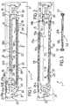
- a conveyor according to the invention is generally indicated 1 and includes a fixed support structure 2 on which two pairs of guides 10 and 11 are mounted, the first being in an upper position and the second in a lower position in relation to the structure 2.
- These guides are provided to guide the movement of respective trolleys 15 and 16.
- a first plurality of rollers 20 is rotatably mounted on the support structure 2 of the conveyor 1 to guide a pair of belts 25 and 26 for movement along respective paths P1 and P2 which extend between the trolleys 15 and 16.
- two rollers 27 and 28, 29 and 30, respectively are provided on the trolleys 15 and 16; in addition the conveyor according to the invention has conventional drive means 31 and 32 provided to drive the belts 25 and 26 respectively and schematically illustrated in this example as drive pulleys.
- This improvement comprises a flexible element 50 having ends 50a and 50b fixed to the upper trolley 15 and which includes a pair of chains 57, of a conventional type, which rotatably support a plurality of rods 58 which extend transversely the flexible element 50.
- the pins 58 are to advantage spaced along respective longitudinal portions of the flexible element 50 starting from the ends 50a and 50b and extending each for substantially the same length as the length of the corresponding loading section 25a and 26b of the paths P1 and P2, as will become clear from the rest of this description.
- the flexible element 50 is guided for movement along a path P3 by a second plurality of rollers 60 rotatably supported by the structure 2 of the conveyor.
- the flexible element 50 is held by a pair of rollers 60a and 60b of the rollers 60 against the aforementioned loading sections 25a and 26b of the paths of the belts 25 and 26, along two longitudinal portions 61a and 62b of the path P3 which extend from the ends 50a and 50b respectively; in particular, along the longitudinal sections 61a and 62b, the rods 58 of the flexible element 50 are in contact with the lower surfaces of the belts 25 and 26, while the chains 57 extend alongside them (see Figure 3).
- the two belts 25 and 26 are driven by their respective drive means 31 and 32 in the directions shown in the drawing; in this operating configuration, the loading section 25a which extends to the left of the upper trolley 15 is shorter than the section 26b. Movement of the upper trolley 15 along its guides 10 towards the loading section 26b results in a simultaneous movement of the lower trolley 16 in the opposite direction along its guides 11, whereby the two belts 25 and 26, whose ends are fixed to these trolleys, also move; it is therefore possible to achieve an operating configuration of the conveyor like that illustrated in Figure 2.
- the flexible element 50 moves as a result of the movement of the upper trolley 15, to which its ends 50a and 50b are fixed; in particular the lengths of the two sections 61a and 62b of the path P3 along which the rods 58 are in contact with belts 25 and 26 along the two loading sections 25a and 26b vary, adapting themselves perfectly to the new configuration of the conveyor.
- rods 58 being rotably mounted in the element 50, produce substantially no friction in contacting the belts.
- the rods are spaced along portions of the flexible element 50 starting from its ends 50a and 50b and extending through distances equal to the maximum lengths of the loading sections 25a and 26b of the paths of the belts 25 and 26, the element 50 will be able to adapt itself to any configuration of the conveyor; that is, the element 50 is able perfectly to support the sections 25a and 26b when each of these is at its maximum or minimum extent, as is seen easily from Figures 1 and 2.
- the flexible element for example, could be made in two parts, each having two ends fixed to the trolleys 15 and 16 respectively instead of just to the trolley 15. It is clear that doing this would reproduce in practice the same teaching as the embodiment referred to in the description.
- rods 58 it would be possible to use other, functionally equivalent elements such as slats or the like; naturally the number of rods provided in the flexible element may also be altered in accordance with the various uses for which the conveyor of the invention is intended. It is obvious that the heavier the products to be transported, the greater the number of rods that must be provided in the flexible element.
- drive rollers be used to facilitate the movement of the flexible element 50 along the path P3, which rollers would accompany the movement of the element 50 during alterations in the operating configuration of the conveyor.
- the improvement of the invention may provide for a single flexible element 50 intended to prevent only one of the two belts 25 and 26 from sagging; in this case, the flexible element 50 would have its ends fixed to the upper trolley 15 and the lower trolley 16 respectively, but would retain the structural and operating characteristics described above.
Landscapes
- Engineering & Computer Science (AREA)
- Mechanical Engineering (AREA)
- Structure Of Belt Conveyors (AREA)
- General Details Of Gearings (AREA)
- Framework For Endless Conveyors (AREA)
Applications Claiming Priority (2)
| Application Number | Priority Date | Filing Date | Title |
|---|---|---|---|
| ITMI930913 | 1993-05-06 | ||
| IT93MI000913A IT1264379B1 (it) | 1993-05-06 | 1993-05-06 | Perfezionamento in un trasportatore di accumulo a nastri |
Publications (2)
| Publication Number | Publication Date |
|---|---|
| EP0623531A2 true EP0623531A2 (de) | 1994-11-09 |
| EP0623531A3 EP0623531A3 (de) | 1996-12-11 |
Family
ID=11366049
Family Applications (1)
| Application Number | Title | Priority Date | Filing Date |
|---|---|---|---|
| EP94201121A Withdrawn EP0623531A3 (de) | 1993-05-06 | 1994-04-23 | Bandförderer zum Speichern. |
Country Status (4)
| Country | Link |
|---|---|
| EP (1) | EP0623531A3 (de) |
| JP (1) | JPH0753024A (de) |
| CA (1) | CA2122213A1 (de) |
| IT (1) | IT1264379B1 (de) |
Cited By (3)
| Publication number | Priority date | Publication date | Assignee | Title |
|---|---|---|---|---|
| EP0919494A1 (de) * | 1997-11-13 | 1999-06-02 | FL Concept | Verfahren und Vorrichtung zum Positionieren von Produkten auf einem aus zwei Förderern bestehenden Transfertsystem |
| CN105197510A (zh) * | 2015-10-30 | 2015-12-30 | 湖州锐格物流科技有限公司 | 一种伸缩装卸皮带机 |
| CN109775250A (zh) * | 2019-01-21 | 2019-05-21 | 金锋馥(滁州)输送机械有限公司 | 一种伸缩式输送机 |
Family Cites Families (2)
| Publication number | Priority date | Publication date | Assignee | Title |
|---|---|---|---|---|
| FR1487578A (fr) * | 1966-07-22 | 1967-07-07 | Gen Electric Co Ltd | Transporteur pour le groupage d'objets |
| DE1915647A1 (de) * | 1969-03-27 | 1970-10-08 | Demag Lauchhammer Gmbh Maschb | Laengenveraenderbares Foerderband |
-
1993
- 1993-05-06 IT IT93MI000913A patent/IT1264379B1/it active IP Right Grant
-
1994
- 1994-04-23 EP EP94201121A patent/EP0623531A3/de not_active Withdrawn
- 1994-04-26 CA CA002122213A patent/CA2122213A1/en not_active Abandoned
- 1994-05-02 JP JP6093549A patent/JPH0753024A/ja active Pending
Cited By (3)
| Publication number | Priority date | Publication date | Assignee | Title |
|---|---|---|---|---|
| EP0919494A1 (de) * | 1997-11-13 | 1999-06-02 | FL Concept | Verfahren und Vorrichtung zum Positionieren von Produkten auf einem aus zwei Förderern bestehenden Transfertsystem |
| CN105197510A (zh) * | 2015-10-30 | 2015-12-30 | 湖州锐格物流科技有限公司 | 一种伸缩装卸皮带机 |
| CN109775250A (zh) * | 2019-01-21 | 2019-05-21 | 金锋馥(滁州)输送机械有限公司 | 一种伸缩式输送机 |
Also Published As
| Publication number | Publication date |
|---|---|
| ITMI930913A1 (it) | 1994-11-06 |
| IT1264379B1 (it) | 1996-09-23 |
| EP0623531A3 (de) | 1996-12-11 |
| CA2122213A1 (en) | 1994-11-07 |
| JPH0753024A (ja) | 1995-02-28 |
| ITMI930913A0 (it) | 1993-05-06 |
Similar Documents
| Publication | Publication Date | Title |
|---|---|---|
| EP0966392B1 (de) | Gelenkiger endlosförderer zum bewegen auf einer dreidimensionalen bahn | |
| US4358010A (en) | Conveyor | |
| US4326626A (en) | Slat conveyors | |
| KR890000597B1 (ko) | 물품의 반송 및 선별 장치 | |
| EP0270143A1 (de) | Abstreifvorrichtung für ein Transportband | |
| EP0369569A1 (de) | Kettenförderer | |
| US5890579A (en) | Apparatus for separating and dealing individual boards from an uninterrupted mat of boards to a conveyor | |
| NL8600734A (nl) | Transporteur. | |
| US9656809B1 (en) | Bar belt with interdigitized elements | |
| EP0333952A1 (de) | Übergabevorrichtung | |
| US3450250A (en) | Conveyor system | |
| US5176248A (en) | Belted chain | |
| US6854586B1 (en) | Unstable article conveying device with diverter having curved path | |
| EP0623531A2 (de) | Bandförderer zum Speichern | |
| US4390093A (en) | Apparatus for conveying sheets such as veneer having improved wicket construction | |
| US5188216A (en) | Magnetic grid | |
| US4004682A (en) | Type S chain | |
| EP1057408A1 (de) | Spiralofen mit verbessertem Riemengetriebe | |
| EP0134060B1 (de) | Fördervorrichtung für Flaschen und ähnliches | |
| DE59800403D1 (de) | Fördervorrichtung für regalkanäle von regallageranlagen | |
| US3000518A (en) | Conveyor distributing system with station selector | |
| ES2017730B3 (es) | Dispositivo para el transporte con carga y descarga de productos de masa. | |
| WO1993014010A1 (en) | Improvements in or relating to conveyors | |
| EP0769124B1 (de) | Trocknungsvorrichtung mit verbesserter führung für geschältes holzfunier | |
| EP3795502B1 (de) | Pufferförderer |
Legal Events
| Date | Code | Title | Description |
|---|---|---|---|
| PUAI | Public reference made under article 153(3) epc to a published international application that has entered the european phase |
Free format text: ORIGINAL CODE: 0009012 |
|
| AK | Designated contracting states |
Kind code of ref document: A2 Designated state(s): AT BE CH DE DK ES FR GB GR IE IT LI LU MC NL PT SE |
|
| RAX | Requested extension states of the european patent have changed |
Free format text: SI PAYMENT 940524 |
|
| PUAL | Search report despatched |
Free format text: ORIGINAL CODE: 0009013 |
|
| AK | Designated contracting states |
Kind code of ref document: A3 Designated state(s): AT BE CH DE DK ES FR GB GR IE IT LI LU MC NL PT SE |
|
| AX | Request for extension of the european patent |
Free format text: SI PAYMENT 940524 |
|
| STAA | Information on the status of an ep patent application or granted ep patent |
Free format text: STATUS: THE APPLICATION IS DEEMED TO BE WITHDRAWN |
|
| 18D | Application deemed to be withdrawn |
Effective date: 19970611 |