EP0623712A2 - Dispositif pour extraire des matériaux séparables d'un liquide - Google Patents
Dispositif pour extraire des matériaux séparables d'un liquide Download PDFInfo
- Publication number
- EP0623712A2 EP0623712A2 EP94106638A EP94106638A EP0623712A2 EP 0623712 A2 EP0623712 A2 EP 0623712A2 EP 94106638 A EP94106638 A EP 94106638A EP 94106638 A EP94106638 A EP 94106638A EP 0623712 A2 EP0623712 A2 EP 0623712A2
- Authority
- EP
- European Patent Office
- Prior art keywords
- separating surface
- screw conveyor
- axis
- separated
- separating
- Prior art date
- Legal status (The legal status is an assumption and is not a legal conclusion. Google has not performed a legal analysis and makes no representation as to the accuracy of the status listed.)
- Withdrawn
Links
- 239000007788 liquid Substances 0.000 title claims abstract description 6
- 238000000926 separation method Methods 0.000 claims abstract description 38
- 239000000463 material Substances 0.000 claims abstract description 22
- 238000003780 insertion Methods 0.000 claims abstract description 13
- 230000037431 insertion Effects 0.000 claims abstract description 13
- XLYOFNOQVPJJNP-UHFFFAOYSA-N water Substances O XLYOFNOQVPJJNP-UHFFFAOYSA-N 0.000 description 5
- XEEYBQQBJWHFJM-UHFFFAOYSA-N Iron Chemical compound [Fe] XEEYBQQBJWHFJM-UHFFFAOYSA-N 0.000 description 2
- 239000000919 ceramic Substances 0.000 description 2
- 238000004065 wastewater treatment Methods 0.000 description 2
- 229910000831 Steel Inorganic materials 0.000 description 1
- 230000001174 ascending effect Effects 0.000 description 1
- 230000005540 biological transmission Effects 0.000 description 1
- 229910010293 ceramic material Inorganic materials 0.000 description 1
- 238000010276 construction Methods 0.000 description 1
- 230000007423 decrease Effects 0.000 description 1
- 238000009434 installation Methods 0.000 description 1
- 229910052742 iron Inorganic materials 0.000 description 1
- 238000012986 modification Methods 0.000 description 1
- 230000004048 modification Effects 0.000 description 1
- 239000010841 municipal wastewater Substances 0.000 description 1
- 244000144977 poultry Species 0.000 description 1
- 239000010865 sewage Substances 0.000 description 1
- 239000010959 steel Substances 0.000 description 1
- 239000004753 textile Substances 0.000 description 1
Images
Classifications
-
- E—FIXED CONSTRUCTIONS
- E03—WATER SUPPLY; SEWERAGE
- E03F—SEWERS; CESSPOOLS
- E03F5/00—Sewerage structures
- E03F5/14—Devices for separating liquid or solid substances from sewage, e.g. sand or sludge traps, rakes or grates
-
- B—PERFORMING OPERATIONS; TRANSPORTING
- B01—PHYSICAL OR CHEMICAL PROCESSES OR APPARATUS IN GENERAL
- B01D—SEPARATION
- B01D33/00—Filters with filtering elements which move during the filtering operation
- B01D33/06—Filters with filtering elements which move during the filtering operation with rotary cylindrical filtering surfaces, e.g. hollow drums
- B01D33/11—Filters with filtering elements which move during the filtering operation with rotary cylindrical filtering surfaces, e.g. hollow drums arranged for outward flow filtration
-
- B—PERFORMING OPERATIONS; TRANSPORTING
- B01—PHYSICAL OR CHEMICAL PROCESSES OR APPARATUS IN GENERAL
- B01D—SEPARATION
- B01D33/00—Filters with filtering elements which move during the filtering operation
- B01D33/27—Filters with filtering elements which move during the filtering operation with rotary filtering surfaces, which are neither cylindrical nor planar, e.g. helical surfaces
- B01D33/275—Filters with filtering elements which move during the filtering operation with rotary filtering surfaces, which are neither cylindrical nor planar, e.g. helical surfaces using contiguous impervious surfaces
-
- B—PERFORMING OPERATIONS; TRANSPORTING
- B01—PHYSICAL OR CHEMICAL PROCESSES OR APPARATUS IN GENERAL
- B01D—SEPARATION
- B01D33/00—Filters with filtering elements which move during the filtering operation
- B01D33/44—Regenerating the filter material in the filter
-
- B—PERFORMING OPERATIONS; TRANSPORTING
- B01—PHYSICAL OR CHEMICAL PROCESSES OR APPARATUS IN GENERAL
- B01D—SEPARATION
- B01D33/00—Filters with filtering elements which move during the filtering operation
- B01D33/44—Regenerating the filter material in the filter
- B01D33/46—Regenerating the filter material in the filter by scrapers, brushes nozzles or the like acting on the cake-side of the filtering element
- B01D33/466—Regenerating the filter material in the filter by scrapers, brushes nozzles or the like acting on the cake-side of the filtering element scrapers
-
- B—PERFORMING OPERATIONS; TRANSPORTING
- B01—PHYSICAL OR CHEMICAL PROCESSES OR APPARATUS IN GENERAL
- B01D—SEPARATION
- B01D33/00—Filters with filtering elements which move during the filtering operation
- B01D33/80—Accessories
- B01D33/801—Driving means, shaft packing systems or the like
-
- B—PERFORMING OPERATIONS; TRANSPORTING
- B01—PHYSICAL OR CHEMICAL PROCESSES OR APPARATUS IN GENERAL
- B01D—SEPARATION
- B01D2201/00—Details relating to filtering apparatus
- B01D2201/28—Position of the filtering element
- B01D2201/287—Filtering elements with a vertical or inclined rotation or symmetry axis
-
- B—PERFORMING OPERATIONS; TRANSPORTING
- B01—PHYSICAL OR CHEMICAL PROCESSES OR APPARATUS IN GENERAL
- B01D—SEPARATION
- B01D29/00—Filters with filtering elements stationary during filtration, e.g. pressure or suction filters, not covered by groups B01D24/00 - B01D27/00; Filtering elements therefor
- B01D29/44—Edge filtering elements, i.e. using contiguous impervious surfaces
- B01D29/46—Edge filtering elements, i.e. using contiguous impervious surfaces of flat, stacked bodies
Definitions
- the invention relates to a device for removing material to be separated from a liquid, with an inclined, liquid-permeable and circumferentially driven separating surface, which has an open end on the inflow side and a preferably closed end face on the inflow side, with an end face arranged parallel to the separating surface and leading to a discharge point for the separated material.
- a screw conveyor with a feed hopper, housing, shaft and conveyor helix conveyor for the material to be separated, and with a detachment device arranged above the feed hopper for the material to be separated from the separation surface.
- the device is used in particular to remove floating and / or floating material from channels in sewage treatment plants, but can also be used in other areas, for example in the textile industry, in slaughterhouses, poultry farms, etc.
- a device of the type described above is known from DE-PS 36 30 755.
- the separating surface is formed in the shape of a cylinder jacket and has a circumferentially driven collecting grate, which consists of a large number of annular disks which are arranged along the circumference at a distance to form a slot.
- a clearing wiper is provided as the steel loosening device, which at least partially engages in the slots between the ring disks.
- the conveying section for the material to be separated which is designed as a screw conveyor device with a feed hopper, housing, shaft and conveying helix, is arranged in the middle of the separating surface, that is to say with its axis coaxial with the axis of the cylindrical jacket-shaped separating surface.
- the device has two drives, namely a first for the screw conveyor and a second for the separating surface.
- the stowage height is limited by the arrangement of the front wall of the hopper, ie the front of the
- the separation surface of the pent-up water level must not be higher or rise than the upper edge of the front wall of the insertion funnel, so that already separated and thrown-in separation material is not washed out by the liquid from the insertion funnel.
- the axial offset of the insertion funnel downwards ensures that all of the separating material which is released from the detachment device and thrown into the insertion funnel also reaches the latter, but at the same time the permissible stowage height is reduced again.
- Another disadvantage is that this limitation of the damming height, the separation area in the upper area can only be used partially. In this respect, an increase in the effectively usable separation area cannot be achieved with such a device by extending the separation area parallel to its axis. Although it is possible to reduce the angle of the inclination of the axis of the device to the horizontal plane in order thereby to be able to effectively use further surface areas of the separation surface for separation purposes, this disadvantageously increases the overall length of the device when the material to be separated is at a certain level must be raised.
- a similar device is also known from DE-PS 34 20 157.
- a common drive is provided for the screw conveyor and for the separating surface, the drive being transmitted to the separating surface by means of a drive arm which connects the separating surface to the shaft of the screw conveyor.
- the coaxial arrangement of the axes of the screw conveyor device on the one hand and of the separating surface on the other hand is also present here.
- This problem results in the object of the invention to increase the effectively usable separation area in a device of the type described at the outset, without having to change the diameter and thus the channel width at the same time.
- this is achieved in a device of the type described in the introduction in that the axis of the screw conveyor device is arranged offset above the axis of the rotating driven separating surface and preferably at least approximately parallel to it.
- the invention is therefore based on the idea of detaching the axis of the screw conveyor from the axis of the rotating driven separating surface and arranging it in a region above the axis of the separating surface.
- the axis of the screw conveyor does not necessarily have to run perpendicularly above the axis of the separation surface, and it is also not absolutely necessary to maintain the parallelism of the axes. Rather, the arrangement can also be made for example be that the axis of the screw conveyor within a z.
- the feed hopper of the screw conveyor can be provided with constant side walls formed over its length. If the parallel arrangement is left somewhat, this can be carried out in such a way that the side wall of the insertion funnel increases somewhat in the conveying direction, which takes into account on the one hand the increasing amount of material to be separated in the insertion funnel and ultimately the end wall of the insertion funnel facing the jammed water with its upper one Edge is raised particularly far, so that the permissible stowage height is raised particularly far, whereby on the other hand additional areas of the separating surface can be effectively used, ie the water can flow through them.
- a major advantage of the new device can be seen in the fact that it allows the damming height to be increased without changing the channel width and the diameter of the separating surface. With this possibility of an increased stowage height, there is at the same time the further advantage that the separating surface can also be made axially comparatively longer and, as a result, additional surface areas can also be used for separating purposes.
- the separation surface can be rotatably mounted on the housing of the screw conveyor.
- the housing of the screw conveyor is arranged to stand still anyway and is therefore available for storage and support purposes.
- the support and storage takes place at least in the area of the closed end wall of the separation surface, but can also include the area of the open end wall of the separation surface.
- the separating surface can have a cylindrical, non-circular or upward oval shape. In all of these cases it is possible to arrange the axis of the screw conveyor on the one hand and the axis of the separation surface independently of one another.
- a cylindrical jacket-shaped separation surface is used when the separation surface itself is largely rigid, as is the case with a basket made of rolled flat iron or wedge-shaped rods.
- the cylindrical jacket-shaped separating surface can also be designed as a strainer basket, as a basket made of filter material or the like. If the separating surface is formed from mutually movable members, there is also a non-circular shape, e.g. B. in hexagon shape. Even oval, elongated designs are possible, which are then arranged at an angle to increase the permissible stowage height and the effectively usable separation area.
- the detachment device which is driven with the rotating Separation surface comes into operative connection, can be designed as a brush, nozzle strip with water, steam, compressed air, as a stationary scraper or the like.
- the detachment can also be done by vibration. Although it is generally located on the outside of the separation surface, it is assigned to a location relative to the insertion funnel of the offset screw conveyor.
- the separating surface can be supported in the region of the end wall on at least three support arms which are fitted with rollers and which have different lengths according to the axial offset.
- the rigid or movable separation surface is then guided over the fixed rollers, the support arms being supported on the housing of the screw conveyor.
- the support arms have different lengths due to the axial offset.
- support arms in the area of the open end wall.
- These support arms can also be built on the housing of the screw conveyor, can be provided with rollers at their free ends facing the separating surface and can form a second bearing for the separating surface.
- the separation surface can have a length / diameter ratio in the range of approximately 1: 1 to 2: 1. While a length / diameter ratio of approximately 1: 1 has previously been used in the known devices, the new arrangement allows the length / diameter ratio to be increased up to approximately 2: 1 with a constant installation angle of the inclination of the axis of the separation surface. This means that the separating surface can be built comparatively considerably longer, which means that it can be used effectively Area areas of the separation area are enlarged.
- the separating surface itself can be designed as a sieve basket, as a collecting grate, as a link chain rake with conveyor hooks or the like.
- a corresponding screen basket can also be formed from filter material, in particular ceramic material.
- Separate drives can be provided for the screw conveyor device on the one hand and the separating surface on the other hand, so that there is advantageously the possibility of realizing different adapted speeds and speeds on the separating surface on the one hand and on the screw conveyor device on the other hand.
- the drive for the separating surface can also be arranged or mounted on the housing of the screw conveyor device, so that separate storage is not necessary.
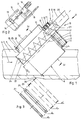
- the device according to FIG. 1 has a separating surface 1 designed in the shape of a cylinder jacket, which can be designed as a circumferential screen basket.
- the separation surface 1 is arranged with its axis 2 inclined at an angle of approximately 45 ° in a channel 3.
- the width of the channel 3 corresponds to the diameter of the separating surface 1.
- the separating surface 1 has a closed end surface 4 at its upper end and an open end surface 5 at its lower end, through which the liquid loaded with the separating material flows according to arrow 6.
- the separating face 1 has an extension 7 which serves for the mounting and the attack of a drive 8.
- Support arms 9 and 10 are provided here, which carry rollers 11 and 12 on their ends facing the extension 7, on which the extension 7 rolls.
- a ring gear 13 which cooperates with a pinion 14 (FIG. 2) which sits on a shaft 15 which is driven by a motor 16 with a gear 17.
- Both the motor 16 with gear 17, which form the essential parts of the drive 8, and the support arms 9 and 10 are arranged and supported on a housing 18 of a screw conveyor device 19.
- the screw conveyor device 19 has an axis 20 which, according to the embodiment according to FIG. 1, is arranged parallel to the axis 2 of the separation surface 1 and is displaced upwards.
- the remaining parts of the check conveyor device 19, namely a shaft 21, a conveyor spiral 22 and a Throw-in funnels 23 with an end wall 24 facing the channel 3 are provided correspondingly offset from the axis 2 of the separating surface 1.
- Axis 20 lies above a plane through axis 2 perpendicular to the plane of the drawing. It is not absolutely necessary for the axis 20 to be perpendicular to the axis 2. It is important that the screw conveyor 19 is provided with its axis 20 offset upwards to the axis 2. In the area of the feed hopper 23, the conveyor helix 22 is arranged without a shaft.
- the upper edge of the end wall 24 of the insertion funnel 23 determines the maximum stowage height and thus also the size of the partial area of the separating surface 1 which can be effectively flowed through and thus used. It can be seen that the effective partial area decreases in the direction of the axis 2 from bottom to top. However, the higher the damming height can be designed, the larger the effectively usable partial area of the separation area 1.
- the upper part of the screw conveyor 19 is not shown in Figure 1. It can be designed similarly to the state of the art. For the sake of clarity, a separate drive for the shaft 21 and the conveyor spiral 22, as is usually placed in the free end region of the housing 18, is also not shown.
- Support arms 25 with rollers 26 can also be arranged in the lower region of the separating surface 1, that is to say in the region of the open end surface 5, on which the cylindrical jacket-shaped separating surface 1 rolls.
- the support arms 25 are supported on the hopper 23, which merges into the housing 18 of the screw conveyor 19.
- FIG 3 are different execution options for a cylindrical jacket-shaped separation surface 1 is shown. This can consist of curved flat bars 27, of wedge-shaped bars 28, of filter material 29 or of filter ceramic 30.
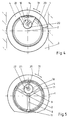
- FIG. 4 shows again exactly that the axis 20 is no longer arranged coaxially to the axis 2, but is offset upwards into a semicircular space.
- the separating surface 1 is driven in accordance with arrow 31 in one or the other direction of rotation, which can be done continuously or in cycles.
- a detachment device 32 (FIG. 1) is provided in the upper area and stationary with respect to the rotatingly driven separation surface 1. which is provided continuously over the length of the separating surface 1 and consists of a brush. a nozzle bar. can consist of swivel wipers or the like.
- the detaching device 32 is arranged relative to the insertion funnel 23. d. H.
- the detaching device 32 is also provided on the outer circumference of the separating surface 1.
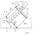
- the separating surface 1 is designed as a link belt rake and is composed of individual parts which are movable relative to one another.
- the separating surface 1 is also driven here by the drive 8.
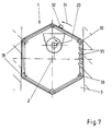
- Rollers 33 and 34 are arranged so that the separating surface 1 is stretched and guided in the form of a hexagon, as is particularly the case in FIG. 7 is recognizable.
- the separating surface 1 can be provided with catch hooks 35, which promote the upward conveyance of the material to be separated on the inside of the separating surface 1.
- the axis 20 can be arranged offset and laterally of the axis 2.
- the detaching device 32 is also provided accordingly.
Landscapes
- Chemical & Material Sciences (AREA)
- Chemical Kinetics & Catalysis (AREA)
- Health & Medical Sciences (AREA)
- Life Sciences & Earth Sciences (AREA)
- Engineering & Computer Science (AREA)
- Hydrology & Water Resources (AREA)
- Public Health (AREA)
- Water Supply & Treatment (AREA)
- Screw Conveyors (AREA)
- Combined Means For Separation Of Solids (AREA)
- Sewage (AREA)
- Filtration Of Liquid (AREA)
Applications Claiming Priority (2)
| Application Number | Priority Date | Filing Date | Title |
|---|---|---|---|
| DE4314673 | 1993-05-04 | ||
| DE4314673A DE4314673C1 (de) | 1993-05-04 | 1993-05-04 | Vorrichtung zum Entfernen von Abscheidegut aus einer Flüssigkeit |
Publications (2)
| Publication Number | Publication Date |
|---|---|
| EP0623712A2 true EP0623712A2 (fr) | 1994-11-09 |
| EP0623712A3 EP0623712A3 (fr) | 1994-11-23 |
Family
ID=6487115
Family Applications (1)
| Application Number | Title | Priority Date | Filing Date |
|---|---|---|---|
| EP19940106638 Withdrawn EP0623712A3 (fr) | 1993-05-04 | 1994-04-28 | Dispositif pour extraire des matériaux séparables d'un liquide |
Country Status (4)
| Country | Link |
|---|---|
| EP (1) | EP0623712A3 (fr) |
| JP (1) | JPH0776871A (fr) |
| CN (1) | CN1095128A (fr) |
| DE (1) | DE4314673C1 (fr) |
Cited By (1)
| Publication number | Priority date | Publication date | Assignee | Title |
|---|---|---|---|---|
| EP1103666A3 (fr) * | 1999-11-23 | 2002-12-18 | NEUHOLD Ges.m.b.H | Dispositif pour la séparation des râtelures d'un courant liquide dans une rigole |
Families Citing this family (8)
| Publication number | Priority date | Publication date | Assignee | Title |
|---|---|---|---|---|
| DE4412124C2 (de) * | 1994-04-08 | 1997-04-30 | Huber Hans Gmbh Maschinen Und | Vorrichtung zum Entfernen von Abscheidegut aus in einem Gerinne strömender Flüssigkeit |
| SE511921C2 (sv) * | 1997-04-04 | 1999-12-13 | Spirac Engineering Ab | Avskiljningsanordning |
| GB9906470D0 (en) * | 1999-03-19 | 1999-05-12 | Jones & Attwood Ltd | Sewage screening apparatus |
| JP4392157B2 (ja) | 2001-10-26 | 2009-12-24 | パナソニック電工株式会社 | 配線板用シート材及びその製造方法、並びに多層板及びその製造方法 |
| DE10302494B3 (de) * | 2003-01-23 | 2004-09-16 | Hans Huber Ag Maschinen- Und Anlagenbau | Vorrichtung zum Entfernen von Siebgut aus in einem Gerinne strömender Flüssigkeit |
| US8695804B2 (en) * | 2007-09-04 | 2014-04-15 | Greystone, Inc. | Sand dewatering device and method |
| JP6220308B2 (ja) * | 2014-04-16 | 2017-10-25 | 住友重機械エンバイロメント株式会社 | 除塵装置、水処理設備、除塵装置の取付方法 |
| CN112495038A (zh) * | 2020-11-10 | 2021-03-16 | 天长市大发化纤有限公司 | 一种带固液分离机构的涤纶短纤维生产线用固体废料清理机构 |
Family Cites Families (3)
| Publication number | Priority date | Publication date | Assignee | Title |
|---|---|---|---|---|
| FR2424053A1 (fr) * | 1978-04-27 | 1979-11-23 | Lecoeur Roger | Dispositif de filtration d'effluents liquides apres floculation |
| CH660854A5 (de) * | 1983-06-01 | 1987-05-29 | Arag Apparatebau | Vorrichtung zum ausscheiden von grobgut aus einem fliessfaehigen medium. |
| DE3630755A1 (de) * | 1986-09-10 | 1988-03-24 | Huber Hans Georg | Vorrichtung zum entfernen von rechen- und/oder siebgut aus in einem gerinne stroemender fluessigkeit |
-
1993
- 1993-05-04 DE DE4314673A patent/DE4314673C1/de not_active Expired - Fee Related
-
1994
- 1994-04-27 JP JP6090092A patent/JPH0776871A/ja not_active Withdrawn
- 1994-04-28 EP EP19940106638 patent/EP0623712A3/fr not_active Withdrawn
- 1994-04-29 CN CN94104677A patent/CN1095128A/zh active Pending
Cited By (1)
| Publication number | Priority date | Publication date | Assignee | Title |
|---|---|---|---|---|
| EP1103666A3 (fr) * | 1999-11-23 | 2002-12-18 | NEUHOLD Ges.m.b.H | Dispositif pour la séparation des râtelures d'un courant liquide dans une rigole |
Also Published As
| Publication number | Publication date |
|---|---|
| CN1095128A (zh) | 1994-11-16 |
| DE4314673C1 (de) | 1994-05-19 |
| EP0623712A3 (fr) | 1994-11-23 |
| JPH0776871A (ja) | 1995-03-20 |
Similar Documents
| Publication | Publication Date | Title |
|---|---|---|
| DE2741710C2 (de) | Vorrichtung zum Trennen von Feststoffen und Flüssigkeiten aus einer Suspension | |
| DE3420157C1 (de) | Vorrichtung zum Entfernen von Rechen- und/oder Siebgut aus in einem Gerinne stroemender Fluessigkeit | |
| DE3630755C2 (fr) | ||
| EP0040425B1 (fr) | Dispositif pour évacuer des matériaux flottants et débris d'un égout, notamment d'une installation d'épuration | |
| EP0565873B1 (fr) | Dispositif pour le compactage et le lavage de produits solides, notamment dans des stations d'épuration | |
| DE3122131C2 (de) | Vorrichtung zur Entnahme und Entwässerung von Feststoffen aus Flüssigkeiten, insbesondere aus Gerinnen von Kläranlagen | |
| DE19744524A1 (de) | Siebvorrichtung für in einem Zulaufrohr ankommendes Abwasser | |
| DE19524276C2 (de) | Vorrichtung zum Entfernen von Abscheidegut aus in einem Gerinne strömender Flüssigkeit | |
| DE2225231C3 (de) | Schneckenpresse | |
| DE4314673C1 (de) | Vorrichtung zum Entfernen von Abscheidegut aus einer Flüssigkeit | |
| DE2751091A1 (de) | Vorrichtung zum abtrennen von fluessigkeit aus einem schlammartigen brei oder gemenge | |
| DE4320678C2 (de) | Vorrichtung zum Entfernen von Rechengut aus einer mit einer verunreinigten Flüssigkeit durchströmten Zulaufrinne, insbesondere von Kläranlagen | |
| DE4412124C2 (de) | Vorrichtung zum Entfernen von Abscheidegut aus in einem Gerinne strömender Flüssigkeit | |
| EP0062628B1 (fr) | Dispositif de déshydratation en marche continue | |
| DE4213847A1 (de) | Geraet fuer die mechanische reinigung von fluessigkeiten in gerinnen oder in behaeltern | |
| DE4328476A1 (de) | Vorrichtung zum Austragen von festen Bestandteilen aus einem Fluid | |
| DE2415593C2 (de) | Silo zum Speichern von schüttfähigem, jedoch schwerfließendem Gut | |
| DE4235903C2 (de) | Vorrichtung zum Entfernen von Abscheidegut aus einer in einem Gerinne strömender Flüssigkeit | |
| DE2342516A1 (de) | Maschine fuer das schaelen oder eine aehnliche oberflaechenbehandlung von koernerfruechten | |
| DE4006970A1 (de) | Vorrichtung zur reinigung von abwasser | |
| DE4338905C1 (de) | Vorrichtung zum Entfernen von Rechen- und/oder Siebgut aus in einem Gerinne strömender Flüssigkeit | |
| DE8905963U1 (de) | Vorrichtung zum Entfernen von Rechen- und/oder Siebgut aus einem Gerinne strömender Flüssigkeit | |
| DE2832277C2 (fr) | ||
| DE202015001595U1 (de) | Vorrichtung zur Filterung von Flüssigkeiten | |
| DE3915529A1 (de) | Vorrichtung zum entfernen von rechen- und/oder siebgut aus einem gerinne stroemender fluessigkeiten |
Legal Events
| Date | Code | Title | Description |
|---|---|---|---|
| PUAI | Public reference made under article 153(3) epc to a published international application that has entered the european phase |
Free format text: ORIGINAL CODE: 0009012 |
|
| PUAL | Search report despatched |
Free format text: ORIGINAL CODE: 0009013 |
|
| AK | Designated contracting states |
Kind code of ref document: A2 Designated state(s): AT BE CH ES FR GB IT LI NL |
|
| AK | Designated contracting states |
Kind code of ref document: A3 Designated state(s): AT BE CH ES FR GB IT LI NL |
|
| RAP1 | Party data changed (applicant data changed or rights of an application transferred) |
Owner name: HANS HUBER GMBH MASCHINEN- UND ANLAGENBAU |
|
| 17P | Request for examination filed |
Effective date: 19941123 |
|
| 17Q | First examination report despatched |
Effective date: 19950124 |
|
| STAA | Information on the status of an ep patent application or granted ep patent |
Free format text: STATUS: THE APPLICATION HAS BEEN WITHDRAWN |
|
| 18W | Application withdrawn |
Withdrawal date: 19951026 |