EP0623735A1 - Méthode et dispositif pour le refroidissement d'un joint pour l'arbe d'une machine - Google Patents
Méthode et dispositif pour le refroidissement d'un joint pour l'arbe d'une machine Download PDFInfo
- Publication number
- EP0623735A1 EP0623735A1 EP94303186A EP94303186A EP0623735A1 EP 0623735 A1 EP0623735 A1 EP 0623735A1 EP 94303186 A EP94303186 A EP 94303186A EP 94303186 A EP94303186 A EP 94303186A EP 0623735 A1 EP0623735 A1 EP 0623735A1
- Authority
- EP
- European Patent Office
- Prior art keywords
- chamber
- seal
- liquid
- vapor
- pressure
- Prior art date
- Legal status (The legal status is an assumption and is not a legal conclusion. Google has not performed a legal analysis and makes no representation as to the accuracy of the status listed.)
- Granted
Links
- 238000001816 cooling Methods 0.000 title claims abstract description 25
- 238000000034 method Methods 0.000 title claims description 9
- 239000007788 liquid Substances 0.000 claims abstract description 38
- 239000012530 fluid Substances 0.000 claims description 50
- 239000006200 vaporizer Substances 0.000 claims description 12
- 230000008016 vaporization Effects 0.000 claims description 3
- 238000005507 spraying Methods 0.000 claims 1
- 239000000203 mixture Substances 0.000 description 7
- OFBQJSOFQDEBGM-UHFFFAOYSA-N Pentane Chemical compound CCCCC OFBQJSOFQDEBGM-UHFFFAOYSA-N 0.000 description 6
- QWTDNUCVQCZILF-UHFFFAOYSA-N isopentane Chemical compound CCC(C)C QWTDNUCVQCZILF-UHFFFAOYSA-N 0.000 description 4
- 238000012423 maintenance Methods 0.000 description 4
- 239000007921 spray Substances 0.000 description 4
- 230000002411 adverse Effects 0.000 description 3
- 239000002826 coolant Substances 0.000 description 3
- 239000000110 cooling liquid Substances 0.000 description 3
- 238000010586 diagram Methods 0.000 description 3
- 230000004048 modification Effects 0.000 description 3
- 238000012986 modification Methods 0.000 description 3
- 238000007789 sealing Methods 0.000 description 3
- 230000004888 barrier function Effects 0.000 description 2
- AFABGHUZZDYHJO-UHFFFAOYSA-N dimethyl butane Natural products CCCC(C)C AFABGHUZZDYHJO-UHFFFAOYSA-N 0.000 description 2
- 238000001704 evaporation Methods 0.000 description 2
- 238000010438 heat treatment Methods 0.000 description 2
- 239000003595 mist Substances 0.000 description 2
- 230000001105 regulatory effect Effects 0.000 description 2
- 230000035939 shock Effects 0.000 description 2
- 238000005482 strain hardening Methods 0.000 description 2
- 239000004215 Carbon black (E152) Substances 0.000 description 1
- 230000009286 beneficial effect Effects 0.000 description 1
- 238000002485 combustion reaction Methods 0.000 description 1
- 230000003750 conditioning effect Effects 0.000 description 1
- 239000000356 contaminant Substances 0.000 description 1
- 239000012809 cooling fluid Substances 0.000 description 1
- 238000013461 design Methods 0.000 description 1
- 230000005611 electricity Effects 0.000 description 1
- 230000008020 evaporation Effects 0.000 description 1
- 238000000605 extraction Methods 0.000 description 1
- 229930195733 hydrocarbon Natural products 0.000 description 1
- 150000002430 hydrocarbons Chemical class 0.000 description 1
- 239000000463 material Substances 0.000 description 1
- 239000002480 mineral oil Substances 0.000 description 1
- 235000010446 mineral oil Nutrition 0.000 description 1
- 238000002156 mixing Methods 0.000 description 1
- 239000003921 oil Substances 0.000 description 1
- 230000009467 reduction Effects 0.000 description 1
- 230000004044 response Effects 0.000 description 1
- 238000012546 transfer Methods 0.000 description 1
- XLYOFNOQVPJJNP-UHFFFAOYSA-N water Substances O XLYOFNOQVPJJNP-UHFFFAOYSA-N 0.000 description 1
Images

Classifications
-
- F—MECHANICAL ENGINEERING; LIGHTING; HEATING; WEAPONS; BLASTING
- F01—MACHINES OR ENGINES IN GENERAL; ENGINE PLANTS IN GENERAL; STEAM ENGINES
- F01D—NON-POSITIVE DISPLACEMENT MACHINES OR ENGINES, e.g. STEAM TURBINES
- F01D5/00—Blades; Blade-carrying members; Heating, heat-insulating, cooling or antivibration means on the blades or the members
- F01D5/02—Blade-carrying members, e.g. rotors
-
- F—MECHANICAL ENGINEERING; LIGHTING; HEATING; WEAPONS; BLASTING
- F01—MACHINES OR ENGINES IN GENERAL; ENGINE PLANTS IN GENERAL; STEAM ENGINES
- F01D—NON-POSITIVE DISPLACEMENT MACHINES OR ENGINES, e.g. STEAM TURBINES
- F01D11/00—Preventing or minimising internal leakage of working-fluid, e.g. between stages
-
- F—MECHANICAL ENGINEERING; LIGHTING; HEATING; WEAPONS; BLASTING
- F01—MACHINES OR ENGINES IN GENERAL; ENGINE PLANTS IN GENERAL; STEAM ENGINES
- F01D—NON-POSITIVE DISPLACEMENT MACHINES OR ENGINES, e.g. STEAM TURBINES
- F01D25/00—Component parts, details, or accessories, not provided for in, or of interest apart from, other groups
- F01D25/08—Cooling; Heating; Heat-insulation
- F01D25/12—Cooling
- F01D25/125—Cooling of bearings
Definitions
- This invention relates to a method of and apparatus for cooling a seal for machinery including rotating machinery, and more particularly, for cooling the seal of a turbine shaft.
- Rotating machinery such as turbine wheels mounted on a shaft, require rotary seals in the region where the shaft passes through the pressure chamber that contains the turbine wheels. Such seals inhibit leakage of working fluid from the pressure chamber into the seal operating environment and then into the atmosphere. In addition, seals are also required in other machinery.
- Seals for rotating machinery usually comprise a labyrinth seal followed by a mechanical seal.
- Labyrinth seals serve to restrict the rate of flow of working fluid and reduce its pressure toward atmospheric pressure, but not to prevent or contain the flow.
- labyrinth seals have many compartments positioned very close to the surface of the shaft for presenting to the working fluid in the pressure chamber a torturous path that serves to reduce pressure and inhibit, but not halt leakage.
- a mechanical seal serves to contain the working fluid. The extent to which containment is achieved depends on the design of the seal and the nature of the working fluid involved.
- Seal life is adversely affected by high operating pressure which tends to distort seal faces.
- High operating pressure also increases wear rate, heat generated at the seal faces which further distorts seal faces and results in increased leakage.
- the high pressure increases power consumption for the turbine sealing system.
- Seal life is adversely affected by high operating temperatures of the seal components.
- High seal component temperatures increase wear on the seal faces, and also increase the likelihood that the barrier fluid when used will boil.
- a seal heated by hot pressurized vapor is cooled by providing a chamber in which the seal is located and for containing vapor that leaks thereinto.
- the pressure in the chamber is reduced by connecting it to a source of low pressure; and liquid is supplied to the chamber at a pressure above the reduced pressure of the chamber and at a temperature below the temperature of vapor leaking into the chamber.
- the liquid is introduced into the chamber as droplets for contacting vapor that leaks thereinto thereby cooling the vapor and thus cooling the seal.
- the flow rate of the liquid is adjustable in accordance with the temperature of the liquid in the chamber.
- apparatus for cooling a hot mechanical seal, gas seal or other seal heated by hot pressurized vapor and/or friction includes a chamber for locating therein the seal and for containing vapor and a connection for connecting the chamber to a source of low pressure thereby reducing the pressure in the chamber to a level below the pressure of vapor that flows into the chamber.
- a further connection is provided for supplying liquid to the chamber at a pressure above the reduced pressure of the chamber.
- apparatus is provided for distributing the liquid throughout the chamber in the form of droplets that contact and cool vapors in the chamber, thus cooling the seal.
- the seal may be associated with the turbine of a Rankine cycle power utilizing an organic working fluid, or a power plant utilizing steam.
- the liquid is distributed throughout the chamber in the form of droplets which contact vapor leaking into the chamber through a labyrinth or other seal thus cooling the vapor thereby indirectly cooling the seal by reducing the temperature of the environment surrounding or associated with the seal.
- Indirect cooling of the seal serves to prevent thermal shock to the materials of the seal.
- the seal is part of a turbine that receives vaporized working fluid from a vaporizer and within which the vaporized working fluid expands producing expanded working fluid, and where the expanded working fluid is condensed in a condenser to produce condensate that is returned to a vaporizer by a cycle pump, the chamber containing the seal is connected to the condenser, and the liquid supplied to the chamber is furnished by the cycle pump.
- reference numeral 10 of Fig. 1 designates a power plant into which the present invention is incorporated.
- Power plant 10 includes vaporizer 12 for vaporizing a working fluid, such as water, or an organic fluid (e.g., pentane, or isopentane), and producing vaporized working fluid that is supplied to turbine 14.
- a working fluid such as water, or an organic fluid (e.g., pentane, or isopentane)
- turbine 14 will be a multistage turbine, but the principle of the invention is applicable to a single stage turbine as well.
- Vaporized working fluid supplied to turbine 14 expands in the turbine and produces work which is converted into electricity by a generator (not shown).
- the cooled, expanded working fluid is exhausted into indirect condenser 16 wherein the vaporized working fluid is condensed by the extraction of heat in the coolant supplied to the condenser.
- the condensate at a relatively low pressure and temperature, as compared to the conditions at the outlet of the vaporizer, is pressurized by cycle pump 18 and returned to the vaporizer, completing the working fluid cycle.
- Seal 20 which is the seal between the atmosphere and the pressure chamber (not shown) containing the inlet stage of the turbine, is contained in a seal operating environment that is isolated from the pressure chamber by a labyrinth seal (not shown) and a mechanical seal (not shown) which is to be cooled.
- condensate is supplied to the seal operating environment by pump 18 through valve 22 in connection 19, and the seal operating environment is connected to condenser 16 by connection 17.
- the conditions in the condenser typically will be about 100 o F. at about 20 psia, and the conditions at the outlet of the cycle pump typically will be about 100 o F. at about 300 psia.
- the actual conditions in the seal operating environment can be controlled by valve 22 by regulating the flow of condensate to the environment.
- the leakage of working fluid vapor through the labyrinth seal into the seal operating environment will produce vaporized working fluid at about 150 psia and about 270 o F.
- the cooler liquid which preferably will be distributed throughout the seal operating environment by converting the liquid supplied by the pump into droplets, will interact with the leakage vapor and cool the same by directly transferring heat to the liquid in the droplets and partially evaporating the liquid thus preventing the heating of the seal operating environment. This has the beneficial effect of reducing the temperature of the seal itself without directly cooling the seal with the condensate.
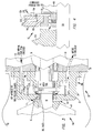
- Apparatus 30 designates apparatus according to the present invention incorporated into turbine 14A.
- Apparatus 30 includes seal operating environment 20A in the form of chamber 32, defined by housing 34 rigidly attached to stationary mounting 36 containing bearing 38 on which shaft 40 of first stage turbine wheel 41 is mounted by a suitable key arrangement.
- Wheel 41 is contained by a housing that defines a high pressure housing or chamber 43 containing hot pressurized and vaporized working fluid.
- Labyrinth seal 42 mounted in face 44 of housing 34 provides the initial resistance to leakage of the hot vaporized working fluid in chamber 43 into seal chamber 34. Such leakage is indicated by chain arrows A and B. Normally, this leakage would heat mechanical seal 46 having sealing faces carried by, and rotating with, shaft 40. This face is in contact with a stationary sealing face carried by hub 48 rigidly attached to housing 36. Normally, both stationary and rotating or dynamic seal faces are cooled by a barrier fluid, e.g., pressurized mineral oil pressurized to about 1.5 to 2 times the reduced chamber pressure (e.g., about 30 to 40 psia in the present embodiment).
- a barrier fluid e.g., pressurized mineral oil pressurized to about 1.5 to 2 times the reduced chamber pressure (e.g., about 30 to 40 psia in the present embodiment).
- Chamber 32 is connected by connection 50 to a source of low pressure, and particularly, to the condenser of the power plant with which turbine 14A is associated. This chamber is also connected via connection 52 to the output of the cycle pump as shown in Fig. 1. Pressurized condensate at the temperature substantially of the condenser is supplied via connection 52 to spray head nozzles 54 that open to the interior of chamber 32, and relatively cold liquid working fluid is sprayed onto cylindrical shield 56 further converting the liquid into fine droplets that form a mist inside chamber 32.
- This mist interacts with hot vapor leakage B thereby cooling this hot vapor by means of direct contact heat transfer of heat in the vapor to liquid contained in the droplets and partial evaporation of the liquid in the droplets and thus forming a mixture of working fluid that is vented and drained by connection 50 into the condenser.
- the temperature of mechanical seal 46 can be maintained at a desired temperature by regulating the amount of liquid supplied to connection 52.
- Shield 56 shields mechanical seal 46 from direct contact with cool liquid from the condenser and thus protects the seal against thermal shock.
- FIG. 4 A second embodiment of the invention is shown in Fig. 4 and designated by reference numeral 60.
- This embodiment includes turbine wheel 41A rigidly attached to shaft 40A which passes though housing 34A, and mechanical seal 46A inside chamber 32A.
- seal 42A engages hub 62 rigidly attached to the shaft.
- Hub 62 includes flange 64 that lies inside chamber 32A close to face 44A of housing 34A and thus rotates together with shaft 40A.
- Conduit 52A in face 44A carries liquid working fluid from the cycle pump to nozzle 54A opening to chamber 32A and facing flange 64.
- Pressurized cold working fluid condensate from the condenser is sprayed into contact with flange 64 producing a spray of fine droplets which are carried by centrifugal force into chamber 32A by reason of the rotational speed of the flange.
- leakage of vaporized working fluid A through seal 42A encounters the spray of cold liquid as soon as the vaporized working fluid passes through seal 42A so that most of leakage B is cooled before entering chamber 34A.
- This embodiment provides rapid engagement of the hot vapor leaking into chamber 32A with cold working fluid, and the rotational movement of flange 64 ensures intimate mixing of the spray of cold liquid with leakage vapors.
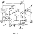
- power plant 10A comprises high pressure turbine 14A serially connected to low pressure turbine 14B.
- vapor from vaporizer 12 is supplied to the inlet of turbine 14A and the exhaust therefrom is supplied to the inlet of turbine 14B.
- High pressure seal environments 70A and 70B, respectively associated with the turbines, are each supplied with cool condensate from condenser 16 by pump 18 via flow conditioning apparatus 19A and 19B, respectively.
- Apparatus 19A and 19B serves both to the properly regulate the flow of condensate to the seal environments, to isolate the flow of cool condensate to the seal environments of the two turbines, and to allow maintenance to the apparatus without interrupting the operation of the turbines.
- Apparatus 19A includes manually operated, infinitely variable, flow control valve 22A, fixed orifice device 23A, filter 24A, and on/off, or shut-off valve 25A serially connected together, and temperature indicator 26A; and apparatus 19B includes corresponding components 22B, 23B, 24B, 25B, and 26B.
- Filters 24A and 24B serve to filter from the condensate supplied to the seal environments any contaminants whose presence would adversely affect the the operation of the seal environments.
- Valves 25A and 25B are preferably manually operated ball-valves that can be selectively operated to disconnect the seal environments from pump 18 when filter replacement or other maintenance operations are necessary allowing the turbines to run for a short time without operation of the seal environments and until these maintenance operations are completed. Furthermore, maintenance operations, when the turbines or power plant is shut down or stopped, are also simplified by this aspect of the present invention. Finally, temperature indicators 26A and 26B provide an indication of the temperature of the fluid exhausted from seal environments 70A and 70B, respectively.
- Valves 22A and 22B are manually operated, preferably in accordance with the temperature of the fluid in lines 17A and 17B connected to seal operating environments. That is to say, the amount of cooling condensate applied to a seal operating environment can be adjusted by an operator by changing the setting of valves 22A and 22B in response to the temperature indicated by indicators 26A and 26B.
- the temperature indicators can be replaced by temperature sensors or transducers that produce control signals in accordance with the temperature of the cooling liquid leaving the seal environment.
- valves 22A and 22B could be replaced with valves which are responsive to such control signals for maintaining the proper flow rate of cooling liquid to the seal environments.
- Modifications of the arrangement shown in Fig. 5 include connecting the turbines in parallel to the vaporizer instead of in series, or connecting several turbines in series or in parallel. This is suggested by the dashed lines extending from the output of the vaporizer, and extending to the inputs to the condenser. Furthermore, the invention is applicable to configurations in which separate vaporizers, feed pumps, and condensers are used. In such case, the flow rate to each seal environment can be controlled individually as a function of the temperature of the cooling liquid to take account of the specific operating conditions encountered by each seal environment. In addition, as shown in Fig.
- turbines 14A and 14B preferably are directly connected to and drive a single, interposed, low speed (e.g., 1500 or 1800 RPM, depending upon the grid frequency) electric generator.
- a single, interposed, low speed e.g. 1500 or 1800 RPM, depending upon the grid frequency
- the seal cooling arrangement of the present invention would be used only as needed.
- the present invention while shown in connection with an organic vapor turbine is also applicable to cooling seals in a steam turbine, gas/vapor compressors, gas/vapor turbines, gas turbines, gas expanders and other types of rotary machines that employ seals for rotating shafts.
- the present invention may be used to cool seals in other machinery or engines including non-rotary machinery or engines, e.g., reciprocating machinery such as diesel engines and internal combustion engines, etc.
- the present invention which utilizes the working fluid itself for the coolant, does not require a separate recirculation system. However, if preferred, a separate auxiliary system can be used for the coolant which may use a fluid different from the working fluid.
Landscapes
- Engineering & Computer Science (AREA)
- Mechanical Engineering (AREA)
- General Engineering & Computer Science (AREA)
- Turbine Rotor Nozzle Sealing (AREA)
- Engine Equipment That Uses Special Cycles (AREA)
Applications Claiming Priority (4)
| Application Number | Priority Date | Filing Date | Title |
|---|---|---|---|
| US199697 | 1988-05-27 | ||
| US5524793A | 1993-05-03 | 1993-05-03 | |
| US55247 | 1993-05-03 | ||
| US19969794A | 1994-02-22 | 1994-02-22 |
Publications (2)
| Publication Number | Publication Date |
|---|---|
| EP0623735A1 true EP0623735A1 (fr) | 1994-11-09 |
| EP0623735B1 EP0623735B1 (fr) | 1998-01-07 |
Family
ID=26734017
Family Applications (1)
| Application Number | Title | Priority Date | Filing Date |
|---|---|---|---|
| EP94303186A Expired - Lifetime EP0623735B1 (fr) | 1993-05-03 | 1994-05-03 | Méthode et dispositif pour le refroidissement d'un joint pour l'arbe d'une machine |
Country Status (4)
| Country | Link |
|---|---|
| EP (1) | EP0623735B1 (fr) |
| DE (1) | DE69407655T2 (fr) |
| IL (1) | IL109498A (fr) |
| NZ (1) | NZ260405A (fr) |
Cited By (2)
| Publication number | Priority date | Publication date | Assignee | Title |
|---|---|---|---|---|
| US8938978B2 (en) | 2011-05-03 | 2015-01-27 | General Electric Company | Gas turbine engine combustor with lobed, three dimensional contouring |
| CN112253259A (zh) * | 2020-09-16 | 2021-01-22 | 上海发电设备成套设计研究院有限责任公司 | 一种透平转子系统 |
Citations (4)
| Publication number | Priority date | Publication date | Assignee | Title |
|---|---|---|---|---|
| FR574739A (fr) * | 1923-01-25 | 1924-07-18 | Brown | Refroidissement des arbres de turbines à vapeur ou à gaz |
| GB513849A (en) * | 1937-03-23 | 1939-10-24 | Maschf Augsburg Nuernberg Ag | An exhaust gas driven turbo-blower |
| FR1170806A (fr) * | 1956-01-09 | 1959-01-19 | United Aircraft Corp | Dispositif de refroidissement pour organes rotatifs |
| JPS6179808A (ja) * | 1984-09-28 | 1986-04-23 | Toshiba Corp | 冷却水ブ−スタポンプ系統制御装置 |
-
1994
- 1994-04-27 NZ NZ260405A patent/NZ260405A/en not_active IP Right Cessation
- 1994-05-02 IL IL10949894A patent/IL109498A/en not_active IP Right Cessation
- 1994-05-03 EP EP94303186A patent/EP0623735B1/fr not_active Expired - Lifetime
- 1994-05-03 DE DE69407655T patent/DE69407655T2/de not_active Expired - Lifetime
Patent Citations (4)
| Publication number | Priority date | Publication date | Assignee | Title |
|---|---|---|---|---|
| FR574739A (fr) * | 1923-01-25 | 1924-07-18 | Brown | Refroidissement des arbres de turbines à vapeur ou à gaz |
| GB513849A (en) * | 1937-03-23 | 1939-10-24 | Maschf Augsburg Nuernberg Ag | An exhaust gas driven turbo-blower |
| FR1170806A (fr) * | 1956-01-09 | 1959-01-19 | United Aircraft Corp | Dispositif de refroidissement pour organes rotatifs |
| JPS6179808A (ja) * | 1984-09-28 | 1986-04-23 | Toshiba Corp | 冷却水ブ−スタポンプ系統制御装置 |
Non-Patent Citations (1)
| Title |
|---|
| PATENT ABSTRACTS OF JAPAN vol. 10, no. 253 (M - 512)<2309> 29 August 1986 (1986-08-29) * |
Cited By (2)
| Publication number | Priority date | Publication date | Assignee | Title |
|---|---|---|---|---|
| US8938978B2 (en) | 2011-05-03 | 2015-01-27 | General Electric Company | Gas turbine engine combustor with lobed, three dimensional contouring |
| CN112253259A (zh) * | 2020-09-16 | 2021-01-22 | 上海发电设备成套设计研究院有限责任公司 | 一种透平转子系统 |
Also Published As
| Publication number | Publication date |
|---|---|
| DE69407655T2 (de) | 1998-05-20 |
| IL109498A0 (en) | 1994-08-26 |
| NZ260405A (en) | 1995-07-26 |
| EP0623735B1 (fr) | 1998-01-07 |
| IL109498A (en) | 2002-07-25 |
| DE69407655D1 (de) | 1998-02-12 |
Similar Documents
| Publication | Publication Date | Title |
|---|---|---|
| US6918252B2 (en) | Method of and apparatus for cooling a seal for machinery | |
| US5743094A (en) | Method of and apparatus for cooling a seal for machinery | |
| US5531073A (en) | Rankine cycle power plant utilizing organic working fluid | |
| US10677255B2 (en) | Dry gas seal cooling arrangement and method | |
| US8448437B2 (en) | System and method of cooling turbines | |
| EP2536923A1 (fr) | Turbine à gaz et système de production d'énergie électrique thermodynamique | |
| CN1091210C (zh) | 汽轮机、汽轮机装置以及冷却汽轮机的方法 | |
| US4189156A (en) | Seal system for a turbomachine employing working fluid in its liquid phase as the sealing fluid | |
| EP0623735B1 (fr) | Méthode et dispositif pour le refroidissement d'un joint pour l'arbe d'une machine | |
| US2463898A (en) | Turbine sealing construction | |
| US5167123A (en) | Flow condensing diffusers for saturated vapor applications | |
| US2649082A (en) | Engine cooling system utilizing waste heat | |
| JP2017115716A (ja) | シール装置 | |
| EP3961002A1 (fr) | Condenseur de vapeur à presse-étoupe pour une centrale électrique à cycle combiné et procédés de fonctionnement associés | |
| NZ248146A (en) | Rankine cycle power plant with two turbine stages; second turbine stage of higher efficiency than first | |
| JPS5768507A (en) | Rankine cycle generating apparatus | |
| RU2002088C1 (ru) | Авиационный парогазовый двигатель | |
| JPS5848734B2 (ja) | 原動機装置 | |
| US11951435B1 (en) | Vapor separation systems and methods | |
| JPS59119003A (ja) | 冷熱発電設備の運転方法 | |
| JPS63294409A (ja) | ボイラ給水ポンプの保護装置 | |
| RO122421B1 (ro) | Sistem de răcire a palelor unui motor-turbină | |
| JPS6179806A (ja) | 原子炉隔離時冷却系 |
Legal Events
| Date | Code | Title | Description |
|---|---|---|---|
| PUAI | Public reference made under article 153(3) epc to a published international application that has entered the european phase |
Free format text: ORIGINAL CODE: 0009012 |
|
| AK | Designated contracting states |
Kind code of ref document: A1 Designated state(s): DE GB IT NL |
|
| 17P | Request for examination filed |
Effective date: 19950412 |
|
| 17Q | First examination report despatched |
Effective date: 19960424 |
|
| GRAG | Despatch of communication of intention to grant |
Free format text: ORIGINAL CODE: EPIDOS AGRA |
|
| GRAG | Despatch of communication of intention to grant |
Free format text: ORIGINAL CODE: EPIDOS AGRA |
|
| GRAH | Despatch of communication of intention to grant a patent |
Free format text: ORIGINAL CODE: EPIDOS IGRA |
|
| GRAH | Despatch of communication of intention to grant a patent |
Free format text: ORIGINAL CODE: EPIDOS IGRA |
|
| GRAA | (expected) grant |
Free format text: ORIGINAL CODE: 0009210 |
|
| AK | Designated contracting states |
Kind code of ref document: B1 Designated state(s): DE GB IT NL |
|
| PG25 | Lapsed in a contracting state [announced via postgrant information from national office to epo] |
Ref country code: NL Free format text: LAPSE BECAUSE OF FAILURE TO SUBMIT A TRANSLATION OF THE DESCRIPTION OR TO PAY THE FEE WITHIN THE PRESCRIBED TIME-LIMIT Effective date: 19980107 |
|
| ITF | It: translation for a ep patent filed | ||
| REF | Corresponds to: |
Ref document number: 69407655 Country of ref document: DE Date of ref document: 19980212 |
|
| NLV1 | Nl: lapsed or annulled due to failure to fulfill the requirements of art. 29p and 29m of the patents act | ||
| PLBE | No opposition filed within time limit |
Free format text: ORIGINAL CODE: 0009261 |
|
| STAA | Information on the status of an ep patent application or granted ep patent |
Free format text: STATUS: NO OPPOSITION FILED WITHIN TIME LIMIT |
|
| 26N | No opposition filed | ||
| REG | Reference to a national code |
Ref country code: GB Ref legal event code: IF02 |
|
| PGFP | Annual fee paid to national office [announced via postgrant information from national office to epo] |
Ref country code: GB Payment date: 20110427 Year of fee payment: 18 |
|
| PGFP | Annual fee paid to national office [announced via postgrant information from national office to epo] |
Ref country code: DE Payment date: 20120502 Year of fee payment: 19 |
|
| PGFP | Annual fee paid to national office [announced via postgrant information from national office to epo] |
Ref country code: IT Payment date: 20120512 Year of fee payment: 19 |
|
| GBPC | Gb: european patent ceased through non-payment of renewal fee |
Effective date: 20120503 |
|
| PG25 | Lapsed in a contracting state [announced via postgrant information from national office to epo] |
Ref country code: GB Free format text: LAPSE BECAUSE OF NON-PAYMENT OF DUE FEES Effective date: 20120503 |
|
| PG25 | Lapsed in a contracting state [announced via postgrant information from national office to epo] |
Ref country code: DE Free format text: LAPSE BECAUSE OF NON-PAYMENT OF DUE FEES Effective date: 20131203 |
|
| REG | Reference to a national code |
Ref country code: DE Ref legal event code: R119 Ref document number: 69407655 Country of ref document: DE Effective date: 20131203 |
|
| PG25 | Lapsed in a contracting state [announced via postgrant information from national office to epo] |
Ref country code: IT Free format text: LAPSE BECAUSE OF NON-PAYMENT OF DUE FEES Effective date: 20130503 |