EP0623752A1 - Rouet de pompe centrifuge - Google Patents
Rouet de pompe centrifuge Download PDFInfo
- Publication number
- EP0623752A1 EP0623752A1 EP94104842A EP94104842A EP0623752A1 EP 0623752 A1 EP0623752 A1 EP 0623752A1 EP 94104842 A EP94104842 A EP 94104842A EP 94104842 A EP94104842 A EP 94104842A EP 0623752 A1 EP0623752 A1 EP 0623752A1
- Authority
- EP
- European Patent Office
- Prior art keywords
- blade
- impeller
- centrifugal pump
- pump impeller
- blades
- Prior art date
- Legal status (The legal status is an assumption and is not a legal conclusion. Google has not performed a legal analysis and makes no representation as to the accuracy of the status listed.)
- Granted
Links
Images

Classifications
-
- F—MECHANICAL ENGINEERING; LIGHTING; HEATING; WEAPONS; BLASTING
- F04—POSITIVE - DISPLACEMENT MACHINES FOR LIQUIDS; PUMPS FOR LIQUIDS OR ELASTIC FLUIDS
- F04D—NON-POSITIVE-DISPLACEMENT PUMPS
- F04D29/00—Details, component parts, or accessories
- F04D29/18—Rotors
- F04D29/22—Rotors specially for centrifugal pumps
- F04D29/24—Vanes
- F04D29/242—Geometry, shape
-
- F—MECHANICAL ENGINEERING; LIGHTING; HEATING; WEAPONS; BLASTING
- F04—POSITIVE - DISPLACEMENT MACHINES FOR LIQUIDS; PUMPS FOR LIQUIDS OR ELASTIC FLUIDS
- F04D—NON-POSITIVE-DISPLACEMENT PUMPS
- F04D29/00—Details, component parts, or accessories
- F04D29/18—Rotors
- F04D29/22—Rotors specially for centrifugal pumps
- F04D29/2261—Rotors specially for centrifugal pumps with special measures
- F04D29/2294—Rotors specially for centrifugal pumps with special measures for protection, e.g. against abrasion
-
- F—MECHANICAL ENGINEERING; LIGHTING; HEATING; WEAPONS; BLASTING
- F05—INDEXING SCHEMES RELATING TO ENGINES OR PUMPS IN VARIOUS SUBCLASSES OF CLASSES F01-F04
- F05D—INDEXING SCHEME FOR ASPECTS RELATING TO NON-POSITIVE-DISPLACEMENT MACHINES OR ENGINES, GAS-TURBINES OR JET-PROPULSION PLANTS
- F05D2240/00—Components
- F05D2240/20—Rotors
- F05D2240/30—Characteristics of rotor blades, i.e. of any element transforming dynamic fluid energy to or from rotational energy and being attached to a rotor
- F05D2240/303—Characteristics of rotor blades, i.e. of any element transforming dynamic fluid energy to or from rotational energy and being attached to a rotor related to the leading edge of a rotor blade
Definitions
- the invention relates to a centrifugal pump impeller for conveying liquids containing solids.
- the invention is based on the problem of developing a measure which prolongs the service life of the pump for the centrifugal pump impellers used for the conveyance of liquids, in which hydroabrasive wear is to be expected.
- An embodiment of the invention provides for this that the transitions of the blade beginnings from the impeller cover disks to the blades take the form of arcs or straight lines with gradients of 0 ° to a maximum of 30 °. Due to the flat rise provided in the area of the middle blade area or the flat transition from the impeller cover disks into the blade tips, a constant increase in speed is brought about in the area of the blade leading edge. This prevents the occurrence of a backflow and thus the formation of a swirl field, which can destroy the cover disks and the blade leading edges.
- the flat transition in the plane of the middle blade surface from the cover disks into the blade tips can be carried out by material application and / or material removal.
- material application and material removal used here are not used in a restrictive and objective manner, but describe the form of change of the invention compared to what is known up to now. In this sense, this also applies to cast, sprayed or similarly made impellers, in which a complete impeller is produced in one operation.
- the impeller model or impeller shape which is then used already has the design which ensures the contours according to the invention.
- the use of the terms material application or material removal refers to the general structural change of a previous blade or contour compared to the new one.
- the measure comparable to material removal predominantly in the area of the impeller cover disk, enables the flat transition in the area of the middle blade area to the beginning of the blade.
- the same effect can be achieved by the measure in the corners between the impeller cover disk and the beginning of the blade, which is comparable to a material application.
- these measures should always be carried out in an extension of the middle blade area beyond the beginning of the blade.
- the measures result in a new course of the blade starts on the impeller cover disk side. To a certain extent, the blade beginnings in the edge area on the impeller cover disc side are clearly drawn forward.
- the configurations described in claims 3 to 5 indicate the orders of magnitude of the transitions or material removal.
- the initial blade thickness is to be understood as the blade thickness that can be measured at the beginning of the blade according to the rounding radius between the suction and pressure sides of the blade. Practical tests have shown that if these values are switched on, the formation of vortices which damage the cover disks and the beginning of the blades can be prevented.
- Another solution to the problem provides that in the area of the impeller inlet diameter and the impeller cover disk on the suction side, the blade tips protrude from the impeller with rounded blade tips.
- the blade tip which usually protrudes in the area of the impeller cover disk on the suction side, has a rounded tip. This influences the flow before entering the impeller, and the formation of a vortex field within the impeller and in front of the beginning of the blade can be effectively prevented.
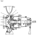
- the centrifugal pump shown in Fig. 1 for conveying media containing solids is of a single-stage design.
- An impeller 2 is shown within a housing 1, the blades 3 of which are shown in the meridian section and projected into the sectional plane are arranged between the suction-side impeller cover plate 4 and the pressure-side impeller cover plate 5.
- the latter is also known under the term support disc.
- the blade tips 6 extend between the two cover disks.
- the inlet cross section of the impeller is limited by the impeller end face 2.1.
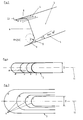
- Fig. 2 shows a flat development of a blade, the section of which runs through the middle blade surface.
- material accumulations 8, 9 of the blade 3 are preceded. Seen in the direction of flow, the transition from the impeller cover disks 4, 5 into the material accumulations 8, 9 acting as an advanced blade leading edge occurs at a very flat angle ⁇ in this plane.
- the radius of this arc is equal to or greater than that 2.5 times the initial blade thickness D.
- the initial blade thickness D is predominantly constant here, but can initially rise over a short distance in the initial area, which is shown as a circular arc in FIGS. 3 and 4, for other contours, such as ellipses.
- Decisive for the transition radius R shown in FIG. 2 from the impeller cover plate to the beginning of the blade 6 is the blade thickness which can be measured at the beginning of the blade; 3 and 4, therefore, the diameter of the semicircle at the character I. This applies if the blade surfaces are arranged perpendicular to the cover disks.
- the blade surfaces are arranged inclined at an angle to the cover disks, then the blade thickness D that results from a cut running parallel to the impeller cover disk surface is decisive.
- the radius R which has a flat increase, also increases.
- FIG. 3 shows a top view of the blade 3 of FIG. 2 cut according to the lines I-I to IV-IV.
- This is a blade with a small transition radius between the blade and the cover plate in the area of the blade channels.
- the lines marked in this illustration with the characters I to IV are comparable in their function with contour lines.
- the dash-dotted line 11 corresponds to the plane of the middle blade surface, the blade thickness of the blade tips 6 was marked with D.
- FIG. 4 shows an embodiment in which the blade 3 merges directly into the cover plate without a radius of rounding.
- FIG 5 shows an embodiment in which a flat transition 13 in the plane of the middle blade surface to the blade tips 6 takes place both by a material removal 12 in the area of the cover disks 4, 5 and by a material application 8, 9 at the blade tips 6 .
- the section lines I to IV shown here run parallel to the cover plate. This course of the cutting line results in a blade contour corresponding to a height profile, as was shown in FIGS. 3 and 4.
- the material removal 12 carried out on the cover disks should be at least twice greater than the initial blade thickness D. In this illustration, the material removal 12 extends into the blade channel. With an appropriate design of the blade transition to the cover plate, the expansion can also end before the blade starts and leave the blade channels unaffected.
- FIG. 6 shows a blade tip (14) which is drawn forward beyond the impeller end face 2.1 in the area of the suction-side impeller cover disk 4. In the area of the impeller cover disk 5 on the pressure side, the flat rise into the blade tips 6 already discussed above is shown.
Landscapes
- Engineering & Computer Science (AREA)
- Mechanical Engineering (AREA)
- General Engineering & Computer Science (AREA)
- Physics & Mathematics (AREA)
- Geometry (AREA)
- Structures Of Non-Positive Displacement Pumps (AREA)
Applications Claiming Priority (2)
| Application Number | Priority Date | Filing Date | Title |
|---|---|---|---|
| DE4311746A DE4311746A1 (de) | 1993-04-08 | 1993-04-08 | Kreiselpumpenlaufrad |
| DE4311746 | 1993-04-08 |
Publications (2)
| Publication Number | Publication Date |
|---|---|
| EP0623752A1 true EP0623752A1 (fr) | 1994-11-09 |
| EP0623752B1 EP0623752B1 (fr) | 1998-09-09 |
Family
ID=6485168
Family Applications (1)
| Application Number | Title | Priority Date | Filing Date |
|---|---|---|---|
| EP94104842A Expired - Lifetime EP0623752B1 (fr) | 1993-04-08 | 1994-03-28 | Rouet de pompe centrifuge |
Country Status (3)
| Country | Link |
|---|---|
| US (1) | US5478200A (fr) |
| EP (1) | EP0623752B1 (fr) |
| DE (2) | DE4311746A1 (fr) |
Families Citing this family (17)
| Publication number | Priority date | Publication date | Assignee | Title |
|---|---|---|---|---|
| JPH0988887A (ja) * | 1995-09-20 | 1997-03-31 | Unisia Jecs Corp | ウォータポンプ |
| US6435829B1 (en) | 2000-02-03 | 2002-08-20 | The Boeing Company | High suction performance and low cost inducer design blade geometry |
| US6589015B1 (en) | 2002-05-08 | 2003-07-08 | Pratt & Whitney Canada Corp. | Discrete passage diffuser |
| JP4663259B2 (ja) * | 2004-06-18 | 2011-04-06 | 日立アプライアンス株式会社 | 送風機及び電気掃除機 |
| CN102369356B (zh) | 2008-09-10 | 2014-11-19 | 滨特尔泵集团股份有限公司 | 高效、多级离心泵及其装配方法 |
| US8235648B2 (en) * | 2008-09-26 | 2012-08-07 | Pratt & Whitney Canada Corp. | Diffuser with enhanced surge margin |
| JP5164932B2 (ja) * | 2009-06-11 | 2013-03-21 | 三菱電機株式会社 | ターボファンおよび空気調和機 |
| EP2486283B1 (fr) * | 2009-10-08 | 2018-12-05 | Sulzer Management AG | Roue de pompe |
| US8998582B2 (en) | 2010-11-15 | 2015-04-07 | Sundyne, Llc | Flow vector control for high speed centrifugal pumps |
| CN106337833A (zh) | 2015-07-06 | 2017-01-18 | 杭州三花研究院有限公司 | 叶轮、离心泵以及电驱动泵 |
| US9926942B2 (en) | 2015-10-27 | 2018-03-27 | Pratt & Whitney Canada Corp. | Diffuser pipe with vortex generators |
| US10570925B2 (en) | 2015-10-27 | 2020-02-25 | Pratt & Whitney Canada Corp. | Diffuser pipe with splitter vane |
| WO2017175165A1 (fr) * | 2016-04-06 | 2017-10-12 | Flsmidth A/S | Roue à faible vorticité d'entrée ayant des caractéristiques d'usure hydrodynamique améliorées |
| WO2018049435A1 (fr) * | 2016-09-08 | 2018-03-15 | Mechanical Engineering Transcendent Technology (Pty) Ltd | Profil d'aube primaire de turbine |
| US10823197B2 (en) | 2016-12-20 | 2020-11-03 | Pratt & Whitney Canada Corp. | Vane diffuser and method for controlling a compressor having same |
| NL2018044B1 (en) * | 2016-12-22 | 2018-06-29 | Ihc Holland Ie Bv | Impeller with rotor blades for centrifugal pump |
| US11959487B2 (en) * | 2020-09-30 | 2024-04-16 | Weir Slurry Group, Inc. | Centrifugal slurry pump impeller |
Citations (4)
| Publication number | Priority date | Publication date | Assignee | Title |
|---|---|---|---|---|
| US1946273A (en) * | 1932-02-08 | 1934-02-06 | American Manganese Steel Co | Rotary pump impeller |
| US3130678A (en) * | 1961-04-28 | 1964-04-28 | William F Chenault | Centrifugal pump |
| SU1101590A1 (ru) * | 1983-02-17 | 1984-07-07 | Специальное Конструкторско-Технологическое Бюро Герметичных И Скважинных Насосов | Рабочее колесо центробежного насоса |
| GB2256901A (en) * | 1991-06-21 | 1992-12-23 | Ingersoll Rand Co | Impeller for centrifugal pumps. |
Family Cites Families (9)
| Publication number | Priority date | Publication date | Assignee | Title |
|---|---|---|---|---|
| US1246253A (en) * | 1916-10-31 | 1917-11-13 | Alexander T Fraser | Pump. |
| US1947658A (en) * | 1931-12-17 | 1934-02-20 | Pizzuto Nicolas | Impeller and shaft therefor for use in centrifugal and turbine pumps |
| US2625884A (en) * | 1949-02-23 | 1953-01-20 | William H Welsh | Impeller |
| CH294450A (de) * | 1952-12-10 | 1953-11-15 | Schweizer Becker Werner | Zentrifugalpumpe, insbesondere für dickflüssige Medien. |
| US3260443A (en) * | 1964-01-13 | 1966-07-12 | R W Kimbell | Blower |
| US3272429A (en) * | 1964-10-16 | 1966-09-13 | Westinghouse Electric Corp | Rotors of centrifugal fans |
| DE2532791A1 (de) * | 1975-07-22 | 1977-02-10 | Dessair Jean Paul | Vertikal- oder horizontaltraeger fuer die herstellung und einrichtung von bueroraeumen sowie haupt- und hilfsprofile zum zusammenbau eines solchen traegers |
| DD253279A1 (de) * | 1986-10-09 | 1988-01-13 | Pumpen & Verdichter Veb K | Pumpenlaufrad fuer die foerderung von fluessigkeits-feststoff-gemischen |
| DE3704360A1 (de) * | 1987-02-12 | 1988-08-25 | Klein Schanzlin & Becker Ag | Kreiselpumpe zur foerderung von feststoffhaltigen fluessigkeiten |
-
1993
- 1993-04-08 DE DE4311746A patent/DE4311746A1/de not_active Withdrawn
-
1994
- 1994-03-28 EP EP94104842A patent/EP0623752B1/fr not_active Expired - Lifetime
- 1994-03-28 DE DE59406861T patent/DE59406861D1/de not_active Expired - Lifetime
- 1994-04-06 US US08/224,640 patent/US5478200A/en not_active Expired - Lifetime
Patent Citations (4)
| Publication number | Priority date | Publication date | Assignee | Title |
|---|---|---|---|---|
| US1946273A (en) * | 1932-02-08 | 1934-02-06 | American Manganese Steel Co | Rotary pump impeller |
| US3130678A (en) * | 1961-04-28 | 1964-04-28 | William F Chenault | Centrifugal pump |
| SU1101590A1 (ru) * | 1983-02-17 | 1984-07-07 | Специальное Конструкторско-Технологическое Бюро Герметичных И Скважинных Насосов | Рабочее колесо центробежного насоса |
| GB2256901A (en) * | 1991-06-21 | 1992-12-23 | Ingersoll Rand Co | Impeller for centrifugal pumps. |
Non-Patent Citations (1)
| Title |
|---|
| SOVIET PATENTS ABSTRACTS Section PQ Week 8507, 27 March 1985 Derwent World Patents Index; Class Q56, AN 85-043087 * |
Also Published As
| Publication number | Publication date |
|---|---|
| US5478200A (en) | 1995-12-26 |
| EP0623752B1 (fr) | 1998-09-09 |
| DE59406861D1 (de) | 1998-10-15 |
| DE4311746A1 (de) | 1994-10-13 |
Similar Documents
| Publication | Publication Date | Title |
|---|---|---|
| EP0623752A1 (fr) | Rouet de pompe centrifuge | |
| DE3103595A1 (de) | Diffusor einer fliehkraft-fluidmaschine | |
| EP0721546A1 (fr) | Turbomachine a usure par abrasion reduite | |
| DE4006604A1 (de) | Vorrichtung zum fluidisieren, entgasen und pumpen einer zellulosefasermaterialsuspension | |
| DE2708368C2 (de) | Laufrad für Kreiselpumpen | |
| EP0733805B1 (fr) | Forme de paroi empêchant le dépÔt de fibres | |
| DE4208202A1 (de) | Zentrifugalpumpe | |
| DD300241A5 (de) | Kreiselpumpengehäuse in Blechbauweise | |
| DE2524556B2 (de) | Einlaßgehäuse für einen Axialverdichter | |
| EP1891334B9 (fr) | Pompe centrifuge | |
| DE3843428C2 (de) | Kreiselpumpenlaufrad geringer spezifischer Drehzahl | |
| EP0013942B1 (fr) | Pompe centrifuge pour liquides contenant des matières solides | |
| DE4041545C2 (fr) | ||
| DE897616C (de) | Axial oder konisch durchstroemtes Geblaese oder axial oder konisch durchstroemte Pumpe zur Foerderung von Gasen oder Fluessigkeiten mit positivem Reaktionsgrad | |
| DE102015003224A1 (de) | Selbstansaugende Pumpe | |
| EP3388671B1 (fr) | Pompe à roue à aubes | |
| DE8614641U1 (de) | Kreiselpumpe | |
| EP0733808A1 (fr) | Pompe centrifuge | |
| EP0599204A1 (fr) | Unité de pompe submersible | |
| EP1538369A1 (fr) | Contour de guidage d'huile dans un carter de transmission | |
| DE10200579A1 (de) | Selbstansaugende Kreiselpumpe | |
| DE3245766C2 (de) | Als Turbine betriebene Kreiselpumpe | |
| DE3022206C2 (de) | Axialverdichter mit verschobener Pumpgrenze | |
| DE202004019506U1 (de) | Seitenkanalverdichter | |
| DE4431947A1 (de) | Strömungsmaschine mit verringertem abrasiven Verschleiß |
Legal Events
| Date | Code | Title | Description |
|---|---|---|---|
| PUAI | Public reference made under article 153(3) epc to a published international application that has entered the european phase |
Free format text: ORIGINAL CODE: 0009012 |
|
| AK | Designated contracting states |
Kind code of ref document: A1 Designated state(s): DE FR GB IT |
|
| 17P | Request for examination filed |
Effective date: 19950228 |
|
| 17Q | First examination report despatched |
Effective date: 19951218 |
|
| GRAG | Despatch of communication of intention to grant |
Free format text: ORIGINAL CODE: EPIDOS AGRA |
|
| GRAG | Despatch of communication of intention to grant |
Free format text: ORIGINAL CODE: EPIDOS AGRA |
|
| GRAH | Despatch of communication of intention to grant a patent |
Free format text: ORIGINAL CODE: EPIDOS IGRA |
|
| GRAH | Despatch of communication of intention to grant a patent |
Free format text: ORIGINAL CODE: EPIDOS IGRA |
|
| GRAA | (expected) grant |
Free format text: ORIGINAL CODE: 0009210 |
|
| AK | Designated contracting states |
Kind code of ref document: B1 Designated state(s): DE FR GB IT |
|
| PG25 | Lapsed in a contracting state [announced via postgrant information from national office to epo] |
Ref country code: IT Free format text: LAPSE BECAUSE OF FAILURE TO SUBMIT A TRANSLATION OF THE DESCRIPTION OR TO PAY THE FEE WITHIN THE PRE;WARNING: LAPSES OF ITALIAN PATENTS WITH EFFECTIVE DATE BEFORE 2007 MAY HAVE OCCURRED AT ANY TIME BEFORE 2007. THE CORRECT EFFECTIVE DATE MAY BE DIFFERENT FROM THE ONE RECORDED.SCRIBED TIME-LIMIT Effective date: 19980909 Ref country code: GB Free format text: LAPSE BECAUSE OF FAILURE TO SUBMIT A TRANSLATION OF THE DESCRIPTION OR TO PAY THE FEE WITHIN THE PRESCRIBED TIME-LIMIT Effective date: 19980909 |
|
| REF | Corresponds to: |
Ref document number: 59406861 Country of ref document: DE Date of ref document: 19981015 |
|
| ET | Fr: translation filed | ||
| GBV | Gb: ep patent (uk) treated as always having been void in accordance with gb section 77(7)/1977 [no translation filed] |
Effective date: 19980909 |
|
| PLBE | No opposition filed within time limit |
Free format text: ORIGINAL CODE: 0009261 |
|
| STAA | Information on the status of an ep patent application or granted ep patent |
Free format text: STATUS: NO OPPOSITION FILED WITHIN TIME LIMIT |
|
| 26N | No opposition filed | ||
| PGFP | Annual fee paid to national office [announced via postgrant information from national office to epo] |
Ref country code: DE Payment date: 20130312 Year of fee payment: 20 |
|
| PGFP | Annual fee paid to national office [announced via postgrant information from national office to epo] |
Ref country code: FR Payment date: 20130419 Year of fee payment: 20 |
|
| REG | Reference to a national code |
Ref country code: DE Ref legal event code: R071 Ref document number: 59406861 Country of ref document: DE |
|
| REG | Reference to a national code |
Ref country code: DE Ref legal event code: R071 Ref document number: 59406861 Country of ref document: DE |
|
| PG25 | Lapsed in a contracting state [announced via postgrant information from national office to epo] |
Ref country code: DE Free format text: LAPSE BECAUSE OF EXPIRATION OF PROTECTION Effective date: 20140329 |