EP0623816A2 - Geräusch-Prüfvorrichtung - Google Patents
Geräusch-Prüfvorrichtung Download PDFInfo
- Publication number
- EP0623816A2 EP0623816A2 EP94302832A EP94302832A EP0623816A2 EP 0623816 A2 EP0623816 A2 EP 0623816A2 EP 94302832 A EP94302832 A EP 94302832A EP 94302832 A EP94302832 A EP 94302832A EP 0623816 A2 EP0623816 A2 EP 0623816A2
- Authority
- EP
- European Patent Office
- Prior art keywords
- noise
- signals
- board
- sources
- transmission
- Prior art date
- Legal status (The legal status is an assumption and is not a legal conclusion. Google has not performed a legal analysis and makes no representation as to the accuracy of the status listed.)
- Withdrawn
Links
Images










Classifications
-
- G—PHYSICS
- G01—MEASURING; TESTING
- G01M—TESTING STATIC OR DYNAMIC BALANCE OF MACHINES OR STRUCTURES; TESTING OF STRUCTURES OR APPARATUS, NOT OTHERWISE PROVIDED FOR
- G01M13/00—Testing of machine parts
- G01M13/02—Gearings; Transmission mechanisms
- G01M13/028—Acoustic or vibration analysis
Definitions
- the present invention relates generally to an electrical circuit, for cooperation with a set of noise sensitive electrical instruments and a computer to provide a stand-alone noise testing device.
- the circuit according to a predetermined schedule of actuation or variation, and at predetermined time intervals, accepts and processes output signals from the test instruments for subsequent analysis by the computer.
- the present circuit be implemented as a single circuit board, and be locatable as an auxiliary unit in a suitable space or expansion slot of the computer.
- the circuit itself provides multipath, bi-directional communication, preferably through a single first plug/socket unit connection, with the PC, and further multipath, bi-directional communication, preferably through a single second plug/socket unit connection, with a set of test instruments.
- Preferably as many functions as possible are allotted to the standard facilities of the interconnected personal computer (PC) so that multi-pin plug and socket means may be used to communicate between the circuit board and the PC. Since various control signals required may be non-standard, these non-standard signals may be generated from unused standard address signals available from most PCs.
- Certain functions such as a clock, oscillator or keying signal may also be included as part of the present circuit for flexibility in adapting to certain PCs when these have non-standard locations or connector terminals for sources of these signals.
- the display facilities of the PC can be used to display test data, but the X and Y signals displayed may be analog signals derived either from certain address signals or from the instruments and their controls.
- a principal embodiment of the invention reads instruments, set up to sense varying test conditions in a machine, feeds X-Y signals to the computer for defining graphs, and processes and feeds to the computer signals derived from progressively varying readings of the instruments.
- the embodiment enables various frequency components to be analyzed, and preferably enables Fourier analyses to be graphed and displayed, stored or printed.
- Noise is becoming an increasingly bothersome hindrance to human comfort, and the most irritating frequency components and hence, sources of the noise can often be discovered by signal processing.
- Prior devices of this type involve the measurement of all noise over a very wide acoustic band, or of a continuous given audio band.
- a feature of the present invention is to observe noise content selectively at points distributed over a given frequency band, to provide a direct portrayal of the potential nuisance quality of machines, either absolutely, or against a standard display deemed to be satisfactory, at some or all of selected frequencies to which the human ear is found or believed to be sensitive, or finds objectionable.
- a machine being tested may have known resonances or cyclic running patterns, e.g. gear tooth meshings, in which case the tests can be directed mainly at specific frequency components and harmonics, or just to selections of these harmonics which are most objectionable to the human ear.
- Computer power and time are saved if observations of such predictable fundamentals and higher or lower order harmonics and sub-harmonics are focused on. For instance, it is possible to predict the audible frequencies to be expected from a heavy vehicle transmission having a certain number of teeth, ratios and stages, run at various typical or test speeds, under certain controlled torque conditions.
- the invention thus provides an auxiliary circuit unit having a first bi-directional multi-path communication connection associated with or mounted thereon, to communicate address words, sensed and quantized instrument data for the displaying signals, and other data or control signals for the instruments.
- Means to generate supply signals for the measurement instruments and for controlled operation of the signal sources may also be included, such sources being typically noisy machines to be measured.
- Means are provided to process the instrument output data for communication to the computer via the first communication means.
- a second bi-directional multi-path communication connection associated with or mounted also on the unit is provided to communicate the control and readout signals between the unit and the instruments or the noise sources.
- noise signals The signals to be measured henceforth will be referred to as "noise" signals.
- noise may be interesting from a point of view of legal or humanly bearable limits, or from the point of view of detecting breakages, damaged teeth, or over-stressed mechanical parts in a transmission.
- One preferred test procedure suitable for a factory environment, to test heavy goods vehicle transmissions for excessive noise, the international standards for which are becoming ever more stringent, is the following. The skilled man will readily adapt such tests for different transmissions or machines.
- a single board embodiment of the present invention will now be described, designed for incorporation into a PC in order to cooperate therewith to provide a self-sufficient noise testing apparatus, which can provide a Fourier analysis and easily read indications of pass or fail without requirement for detailed portrayal of the intermediate analyses.
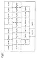
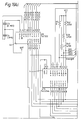
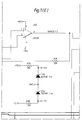
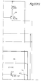
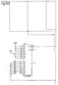
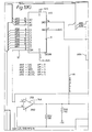
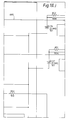
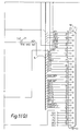
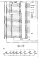
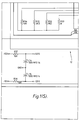
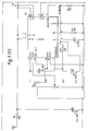
- Figures 1(A) - 1(Z) which should be placed as shown in Figure 1, form a schematic diagram of the circuit of the present invention with Figures 1(Y) and 1(Z) schematically illustrating an optional ac to dc converter circuit.
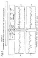
- Figure 2 shows noise measurement curves for each of four meshings in a constant mesh gearbox.
- the present circuit includes a first bi-directional multi-path plug-socket connector 1A having twenty input paths, AO - A19, for binary words representing numerous address signals cycled at random intervals by a PC host (not shown).
- the components schematically shown in Figure 1 are preferably mounted on a single circuit board mountable in an expansion slot or elsewhere within the housing of the host PC.
- Connector 1A feeds the aforementioned address signals to the circuit board, along with some direct voltage levels on conductors B1 to B9 and control pulses on conductors labelled B11 - B14 and A11.
- the address signals themselves are referenced A0 - A19, whereas the terminals of connector 1A on which they appear are labelled A31 - A12 (not to be confused with the address signal references).
- an 8-bit digital word is read out into the computer from the circuit board.
- the bits are referenced DO - D7, and at any instant represent a single amplitude, but which in successive instants represent the possible levels of different signals which thus time-share the eight lines A1 - A9.
- the eight-bit signals DO - D7 thereon are derived from an analog to digital converter 2 described more fully below.
- a control signal AEN also received from the computer on A11 enables measurements to begin or continue, in that the computer microprocessor states the address bus to be adequately stable and/or validated.
- HEX numbers between 300 and 400 are AND-ed in a decoder 4 with signals including the A1 - A3 address signals, in order to generate start signals to the aforementioned devices.
- the base address can be made selectable instead of necessarily AO.
- This start signal enables the successive digital words DO - D7 appearing on terminals 8 - 11 and 13 - 16 to be appropriately identified.
- the aforementioned A1 - A3 address bits from connector 1 are also AND-ed with read or write bits received from the computer on terminals B13, B14 of connector 1A, via a NOR-gate 5.
- one of the HEX numbers between 300 and 400 is chosen by the comparator 3 as the start for A/D converter 2, which chosen number can be varied.
- the DO - D7 output signals from converter 2 time-share the A1 - A8 terminals of connector 1A with input trigger signals, also referenced DO-D7, which initiate multiplexing signals referenced as shown from respective chips which are latches 7 and 8.
- These latches act generally similarly, to take a clock signal from a terminal Y3 of decoder chip 4, and remember the DO - D7 word or value received from the computer at the instants that the Y3 clock signal is present, to sustain the multiplexing and other control signals generated by them until clocked again.
- the computer by this means sets the output of latch chip 7 to the binary value written to that address designated by 306 HEX. Arrangement other than this specific example will readily occur to the skilled person.
- Eight analog signals ANO - AN7 are initiated by the external test instruments and processed to provide eight inputs to be measured, which are fed to a multiplexer 9. There is a need to plot all these signals, preferred origins of which will be described later. Some of these signals represent noise levels requiring plotting against others of the analog signals ANO - AN7 and/or other parameters such as torque or gear ratios. As will be described later, the multiplexer can alternately be chosen to deal with 16 inputs, especially as there are the further necessary software channels readily available. Usually only engine speed will be plotted or displayed on the abscissa, because new plots will be made for different gears or torques. More specifically, microphone and/or accelerometer signals, or rms derivations therefrom, are plotted against speed in a specially advantageous embodiment.
- the converter contains sample and hold means and the aforementioned start signal from terminal YO of gate 4, and certain gating binary signals AM1 - AM3 release the eight analog signals one at a time in turn on a combining output line 10 of the multiplexer chip 9.
- the AM1-AM3 signals and a fourth, AM4 are also used to select the analog noise signals one at a time for rms determinations, as will become clear hereafter.
- variable gain amplifier 12 which can be switched to various values of gain, enabling the output to lie between limits, but the amplification factor can be allowed for in processing the final number in the computer.
- This is routine for comparing an unknown signal with a standard signal of different amplitude, and hence measuring the former.
- the variable signal from an operational amplifier 14A in amplifier 12 is differenced with the actual analog signal each instant appearing on line 10, in amplifier 14A, and fed to a V in terminal of the converter 2.
- the converted analog signals are fed to the computer on lines DO - D7 as aforesaid.
- the OP-amp 14A must have high enough output at low enough impedance at the converter input.
- the shown amplifier U5B may be replaced accordingly by the more powerful, lower output impedance U33 amplifier.
- the origins of the eight analog signals ANO - AN7 are:- ANO first microphone AN1 second microphone AN2 dc tachometer reading AN3 first accelerometer AN4 second accelerometer AN5 rms dc determination of AN0, AN1, AN3 or AN4 AN6 rms dc determination of AN0, AN1, AN3 or AN4 AN7 tachometer triggered delivers dc
- the outputs of each of AN5 and AN6 represents at one time only one selected signal of the four, and is sustained as an rms signal at that level until the next DIN pulse is latched from chip 7.
- the two ac microphone signals are inputted at 14,15 from a second connector 1B dedicated to (a) couple out energization signals or voltages generated on the board, or fed via the board from the host computer, and directed out off-board to energize instruments or to control the machinery to be tested; and (b) to receive as inputs the instrument sensing signals, such as the microphone acoustic sensings.
- the signals 14 and 15 are amplified in separate identical channels by amplifiers 16,17 tuned by filter components such as capacitors 18,19,20,21 and associated resistors, to give respective response curves to amplifiers 16,17, preferably particularly resembling that of the human ear.
- the outputs of these selective amplifiers 16,17 are then inputted to respective linear amplifiers 22,23, which deliver the ac outputs ANO, AN1 limited to ⁇ 3 volts by diode pairs 24,25.
- the two or more microphone sensings will be subjected to identical filtering.
- outputs of several different microphones can be summed in resistance networks, according to required weighting between them, before being evaluated for noise significance.
- the response shaping stages 16-21 may be omitted, or by-passed as shown by inputs 26,27 direct from further appropriate input conductors of connector 1B and applied directly to the linear amplifiers 22,23.
- the presently preferred embodiment is intended to give responses according to their noise nuisance value, not to absolute signal levels which will only be objectionable when occurring at or passing through certain sensitive frequencies.
- a dc input 28 from a tachometer is amplified by a 2902 chip, limited to having a ⁇ 3 volts input range by diode pair 29, and delivered as output AN2.
- Two accelerometers deliver inputs 30,31 which as approximately 10 mV ac signals arrive at amplifiers 32,33, whence they are limited if necessary by diode pairs 34 to around 3 volts ac, they exist as outputs AN3,AN4.
- the accelerometers in this preferred embodiment require respective constant current sources 35,36 derived from 35 volts dc typically not available from the PC host and preferably provided externally of the board.
- the constant currents are fed out via connector 1B on the same lines 30,31 on which the accelerometer ac signal inputs are received from the instruments.
- the accelerometer outputs are not subjected to audio filtering or tuning as are the microphones, in order to give a shaped response curve, such as other than high pass or band pass.
- the inputs are decoupled from the dc supplies by adequately large capacitors 37,38 to handle the low input frequencies.
- the ac signals AN3,AN4 from the accelerometers and the ac signals ANO,AN1 from the microphones are fed to separate original inputs S1-S4 in a multiplexer chip 39 where they are multiplexed and sustained at a fixed level long enough to enable an rms sampling determination using the same control signals from latch 7 that control multiplexer 9.
- One of the four analog signals then is selected to pass between its own S to D path of chip 39, which level is only updated periodically.
- the four multiplexing control signals AM1 - AM4 from latch unit 7 open only one of the S to D paths of multiplexer 39 or 41 at a time, and then only if a DIN pulse is also present thereon at the same instant.
- the selected S to D path is coupled to another stage 40 which delivers rms versions of the selected one of the four analog signals ANO, AN1, AN3, AN4 for a sustained period which has been designated long enough for delivering a reliable rms value at an output AN5.
- Identical circuitry 41,42 produces the same multiplexed selected, and held or sustained one of the four rms signals at a second analog output AN6, generally at different instants since the ST pulse from latch 7 and not the DIN pulse triggers identical multiplexer 41.
- the second multiplexing thereby, and the output AN6 may both be provided for fail-safe redundancy or for facilitating separate analyses.
- the rms chips 40 and 42 are preferably AD636s with appropriate external impedances connected thereto.
- a third multiplexer may be required, if there are 16 noise channels, as described later.
- multiplexers 39-42 constitute an analog rms measurement system and the noise filters are the analog type.
- Major transients can be missed by digitizing too coarsely, so analog is preferred. It is easy to measure digitally over a few thousandths of a second, but not over seconds. The typical operation involves 12,000 samples per second, to produce a 6 kHz Fourier analysis.
- the analog signals ANO-AN7 thus are selected one at a time by the word applied to control multiplexer 9, and the resulting signals in turn are quantized in converter 2 for analysis by the PC host, and for graphing if desired.
- the input analog signals to the converter can be led via an ANACHECK line 44 to connector 1B and hence to be observed by off-board oscilloscope means (not shown).
- This embodiment has one more dc rpm channel and one less ac rpm channel.
- the dc generator was taken externally, off-board.
- a third microphone and filter channel is preferably incorporated for added flexibility.
- one noise measurement is preferably taken on the outputs of all three noise sources added together in analog manner in a resistance network as referred to above.
- Two swept signals for the variable drive to the machine to be tested may be generated from the 35 volt supply from unit 43 by appropriate control of the control words fed from the latches and the computer, to a digital to analog converter 47, to provide up to 20 volts on output lines 48,49 separate dc drives for supplying components of an off-board test rig.
- Converter 47 may be controlled by a word comprising eight bits DO-D7 from an off-board microprocessor, and four bits D8-D11 from latch 8, to give a varying output analog voltage. In another embodiment, 10 volts dc supply was adequate. The supply of 35 volts is usually more conveniently auxiliary, not on the board.
- the microphone outputs of all four alternative meshings of one transmission can be continuously measured and automatically plotted on four adjacent graphs as shown in Figure 2.
- Graph A represents the meshing of the left hand gear pair shown schematically at 50 over 1000 to 2000 rpm.
- Graphs B,C and D are shown in Graphs B,C and D. These graphs can be produced to show the fundamental mesh components and the harmonics thereof.
- the overall noise may for instance be portrayed simultaneously with graphs A-D, on a fifth screen (not shown). It may be convenient to have one or more auxiliary differential amplifiers on board, if board space permits.
- One use can be to sense and display synchromesh engagement times, such as of the gearboxes currently being evaluated for noise by the inventive combination.
- Such an auxiliary amplifier can measure the difference in two rpms as it approaches zero ("in sync"), or it can measure the time over which an acoustic signal note changes frequency or over which a pneumatic gear shifter drive was heavily loaded, i.e. the time to overcome the resistance of the synchromesh.
- the power supplies of the PC are not in general adequate to power all such auxiliaries.
- one auxiliary circuit board can thus convert a PC into a comprehensive and user friendly machinery noise test and display facility, by which the user's attention is concentrated on those noise components likely to be most disturbing and objectionable to humans or possibly to other specifics such as animals, acoustic-sensitive equipment or alarms. Also the system can simplify trouble-shooting and fault diagnostics.
- the acoustic measurement specification can be obtained from IEC Publication 651, 1979 entitled Sonoarea/Sound Level Meters.
Landscapes
- Physics & Mathematics (AREA)
- Acoustics & Sound (AREA)
- General Physics & Mathematics (AREA)
- Measurement Of Mechanical Vibrations Or Ultrasonic Waves (AREA)
Applications Claiming Priority (2)
| Application Number | Priority Date | Filing Date | Title |
|---|---|---|---|
| GB9309086 | 1993-05-01 | ||
| GB939309086A GB9309086D0 (en) | 1993-05-01 | 1993-05-01 | Instrumentation power supply and read unit |
Publications (2)
| Publication Number | Publication Date |
|---|---|
| EP0623816A2 true EP0623816A2 (de) | 1994-11-09 |
| EP0623816A3 EP0623816A3 (de) | 1995-08-23 |
Family
ID=10734843
Family Applications (1)
| Application Number | Title | Priority Date | Filing Date |
|---|---|---|---|
| EP94302832A Withdrawn EP0623816A3 (de) | 1993-05-01 | 1994-04-21 | Geräusch-Prüfvorrichtung. |
Country Status (3)
| Country | Link |
|---|---|
| US (1) | US5661659A (de) |
| EP (1) | EP0623816A3 (de) |
| GB (1) | GB9309086D0 (de) |
Cited By (3)
| Publication number | Priority date | Publication date | Assignee | Title |
|---|---|---|---|---|
| US7827010B2 (en) | 2004-10-15 | 2010-11-02 | Xax Kft. | Device and process for examining the signals of systems releasing them during operation or in response to external excitation |
| US10110336B2 (en) | 2016-07-22 | 2018-10-23 | The Directv Group, Inc. | Determining ambient noise in a device under test electromagnetic compatibility test environment |
| CN109883692A (zh) * | 2019-04-04 | 2019-06-14 | 西安交通大学 | 基于内置编码器信息的广义差分滤波方法 |
Families Citing this family (7)
| Publication number | Priority date | Publication date | Assignee | Title |
|---|---|---|---|---|
| US6510397B1 (en) | 1999-03-13 | 2003-01-21 | Textron Systems Corporation | Method and apparatus for self-diagnosis of a sensor |
| US6694285B1 (en) | 1999-03-13 | 2004-02-17 | Textron System Corporation | Method and apparatus for monitoring rotating machinery |
| US6546814B1 (en) | 1999-03-13 | 2003-04-15 | Textron Systems Corporation | Method and apparatus for estimating torque in rotating machinery |
| US6425293B1 (en) | 1999-03-13 | 2002-07-30 | Textron Systems Corporation | Sensor plug |
| AU2003222669A1 (en) * | 2002-04-22 | 2003-11-03 | Yazaki Corporation | Electrical connectors incorporating low friction coatings and methods for making them |
| EP2498076A1 (de) | 2011-03-11 | 2012-09-12 | Hexagon Technology Center GmbH | Verschleissüberwachung einer Schaltung in einer Stromstation |
| US10788394B2 (en) | 2017-09-12 | 2020-09-29 | General Electric Company | Gearbox sensor arrangement |
Family Cites Families (10)
| Publication number | Priority date | Publication date | Assignee | Title |
|---|---|---|---|---|
| US3758758A (en) * | 1972-03-10 | 1973-09-11 | United Aircraft Corp | Weighting rotational statistical vibration analysis employing sidebands and/or |
| US4257273A (en) * | 1979-07-26 | 1981-03-24 | Minnesota Mining And Manufacturing Company | Sound pressure level meter |
| US4488240A (en) * | 1982-02-01 | 1984-12-11 | Becton, Dickinson And Company | Vibration monitoring system for aircraft engines |
| JPS59164938A (ja) * | 1983-03-09 | 1984-09-18 | Mitsubishi Electric Corp | 歯車異常音検出装置 |
| US4554639A (en) * | 1983-04-06 | 1985-11-19 | E. I. Du Pont De Nemours And Company | Audio dosimeter |
| US4872337A (en) * | 1988-01-29 | 1989-10-10 | Watts Robert J | Nondestructive testing of gears |
| US4931949A (en) * | 1988-03-21 | 1990-06-05 | Monitoring Technology Corporation | Method and apparatus for detecting gear defects |
| US4980844A (en) * | 1988-05-27 | 1990-12-25 | Victor Demjanenko | Method and apparatus for diagnosing the state of a machine |
| SE460315B (sv) * | 1988-10-13 | 1989-09-25 | Ludwik Jan Liszka | Saett att fortloepande oevervaka drifttillstaandet hos en maskin |
| JPH02298825A (ja) * | 1989-05-13 | 1990-12-11 | Nippondenso Co Ltd | 回転機のための異常検査装置 |
-
1993
- 1993-05-01 GB GB939309086A patent/GB9309086D0/en active Pending
-
1994
- 1994-04-21 EP EP94302832A patent/EP0623816A3/de not_active Withdrawn
-
1996
- 1996-11-06 US US08/744,938 patent/US5661659A/en not_active Expired - Lifetime
Cited By (5)
| Publication number | Priority date | Publication date | Assignee | Title |
|---|---|---|---|---|
| US7827010B2 (en) | 2004-10-15 | 2010-11-02 | Xax Kft. | Device and process for examining the signals of systems releasing them during operation or in response to external excitation |
| US10110336B2 (en) | 2016-07-22 | 2018-10-23 | The Directv Group, Inc. | Determining ambient noise in a device under test electromagnetic compatibility test environment |
| US10425178B2 (en) | 2016-07-22 | 2019-09-24 | The Directv Group, Inc. | Determining ambient noise in a device under test electromagnetic compatibility test environment |
| CN109883692A (zh) * | 2019-04-04 | 2019-06-14 | 西安交通大学 | 基于内置编码器信息的广义差分滤波方法 |
| CN109883692B (zh) * | 2019-04-04 | 2020-01-14 | 西安交通大学 | 基于内置编码器信息的广义差分滤波方法 |
Also Published As
| Publication number | Publication date |
|---|---|
| GB9309086D0 (en) | 1993-06-16 |
| EP0623816A3 (de) | 1995-08-23 |
| US5661659A (en) | 1997-08-26 |
Similar Documents
| Publication | Publication Date | Title |
|---|---|---|
| US5511422A (en) | Method and apparatus for analyzing and detecting faults in bearings and other rotating components that slip | |
| Guo et al. | Vibration separation technique based localized tooth fault detection of planetary gear sets: A tutorial | |
| US5661659A (en) | Instrumentation power supply and read unit for testing gearboxes through various speeds and gears | |
| US6208944B1 (en) | Method for determining and displaying spectra for vibration signals | |
| Luo et al. | On-line vibration analysis with fast continuous wavelet algorithm for condition monitoring of bearing | |
| US4980844A (en) | Method and apparatus for diagnosing the state of a machine | |
| EP2373961B1 (de) | Verfahren zur analyse des zustands einer maschine mit einem drehteil | |
| US20040176902A1 (en) | Vibration monitoring system for gas turbine engines | |
| EP1097362A1 (de) | Feststellen von ungewöhnlichen verhalten mit akustischem monitor | |
| US5578937A (en) | Instrument for analysis of electric motors based on slip-poles component | |
| JP3020349B2 (ja) | 異常検出方法及び装置 | |
| JPH0615987B2 (ja) | 振動検出機構の診断方法 | |
| US20210018906A1 (en) | Feature Value Extraction Apparatus, Predicted-Failure-Evidence Diagnosis Apparatus, Design Assistance Apparatus, and Predicted-Failure-Evidence Diagnosis Operation Method | |
| KR920004647B1 (ko) | 회전기계의 진동감시방법 | |
| KR0169714B1 (ko) | 터어빈 발전기 축 비틀림 감시 장치 | |
| Huang et al. | Wireless monitoring of gearbox vibrations with embedded sensors using LabVIEW | |
| RU2643696C1 (ru) | Способ вибрационной диагностики шестерён редуктора газотурбинного двигателя | |
| JPH0652217B2 (ja) | 歯車装置の異常診断装置 | |
| KR20230055741A (ko) | 회전체의 축궤도 진단 시스템 및 방법 | |
| RU2224223C1 (ru) | Устройство для виброакустической диагностики передач зацеплением | |
| RU20962U1 (ru) | Устройство для диагностики передач зацеплением | |
| Mones et al. | Fault Detection of Planetary Gearboxes using a Wireless MEMS Sensor and New Diagnostic Parameters | |
| JP3485095B2 (ja) | 音圧測定自己診断装置 | |
| Al-Arbi et al. | Characterization of vibration transmission paths for gearbox condition monitoring | |
| JPS5924217A (ja) | 車両用騒音分析装置 |
Legal Events
| Date | Code | Title | Description |
|---|---|---|---|
| PUAI | Public reference made under article 153(3) epc to a published international application that has entered the european phase |
Free format text: ORIGINAL CODE: 0009012 |
|
| AK | Designated contracting states |
Kind code of ref document: A2 Designated state(s): DE FR GB IT |
|
| PUAL | Search report despatched |
Free format text: ORIGINAL CODE: 0009013 |
|
| AK | Designated contracting states |
Kind code of ref document: A3 Designated state(s): DE FR GB IT |
|
| 17P | Request for examination filed |
Effective date: 19960202 |
|
| 17Q | First examination report despatched |
Effective date: 19970520 |
|
| STAA | Information on the status of an ep patent application or granted ep patent |
Free format text: STATUS: THE APPLICATION IS DEEMED TO BE WITHDRAWN |
|
| 18D | Application deemed to be withdrawn |
Effective date: 19971001 |