EP0624332B1 - Elément de ressort élastique et élément de support élastique pourvu de tels éléments de ressort - Google Patents
Elément de ressort élastique et élément de support élastique pourvu de tels éléments de ressort Download PDFInfo
- Publication number
- EP0624332B1 EP0624332B1 EP19940201266 EP94201266A EP0624332B1 EP 0624332 B1 EP0624332 B1 EP 0624332B1 EP 19940201266 EP19940201266 EP 19940201266 EP 94201266 A EP94201266 A EP 94201266A EP 0624332 B1 EP0624332 B1 EP 0624332B1
- Authority
- EP
- European Patent Office
- Prior art keywords
- springy
- spring
- elastic
- wire spring
- element according
- Prior art date
- Legal status (The legal status is an assumption and is not a legal conclusion. Google has not performed a legal analysis and makes no representation as to the accuracy of the status listed.)
- Expired - Lifetime
Links
Images
Classifications
-
- F—MECHANICAL ENGINEERING; LIGHTING; HEATING; WEAPONS; BLASTING
- F16—ENGINEERING ELEMENTS AND UNITS; GENERAL MEASURES FOR PRODUCING AND MAINTAINING EFFECTIVE FUNCTIONING OF MACHINES OR INSTALLATIONS; THERMAL INSULATION IN GENERAL
- F16F—SPRINGS; SHOCK-ABSORBERS; MEANS FOR DAMPING VIBRATION
- F16F3/00—Spring units consisting of several springs, e.g. for obtaining a desired spring characteristic
- F16F3/08—Spring units consisting of several springs, e.g. for obtaining a desired spring characteristic with springs made of a material having high internal friction, e.g. rubber
- F16F3/10—Spring units consisting of several springs, e.g. for obtaining a desired spring characteristic with springs made of a material having high internal friction, e.g. rubber combined with springs made of steel or other material having low internal friction
- F16F3/12—Spring units consisting of several springs, e.g. for obtaining a desired spring characteristic with springs made of a material having high internal friction, e.g. rubber combined with springs made of steel or other material having low internal friction the steel spring being in contact with the rubber spring
-
- A—HUMAN NECESSITIES
- A47—FURNITURE; DOMESTIC ARTICLES OR APPLIANCES; COFFEE MILLS; SPICE MILLS; SUCTION CLEANERS IN GENERAL
- A47C—CHAIRS; SOFAS; BEDS
- A47C23/00—Spring mattresses with rigid frame or forming part of the bedstead, e.g. box springs; Divan bases; Slatted bed bases
- A47C23/002—Spring mattresses with rigid frame or forming part of the bedstead, e.g. box springs; Divan bases; Slatted bed bases with separate resilient support elements, e.g. elastomeric springs arranged in a two-dimensional matrix pattern
-
- A—HUMAN NECESSITIES
- A47—FURNITURE; DOMESTIC ARTICLES OR APPLIANCES; COFFEE MILLS; SPICE MILLS; SUCTION CLEANERS IN GENERAL
- A47C—CHAIRS; SOFAS; BEDS
- A47C27/00—Spring, stuffed or fluid mattresses or cushions specially adapted for chairs, beds or sofas
- A47C27/04—Spring, stuffed or fluid mattresses or cushions specially adapted for chairs, beds or sofas with spring inlays
- A47C27/06—Spring inlays or spring units therefor
- A47C27/063—Spring inlays or spring units therefor wrapped or otherwise protected
-
- A—HUMAN NECESSITIES
- A47—FURNITURE; DOMESTIC ARTICLES OR APPLIANCES; COFFEE MILLS; SPICE MILLS; SUCTION CLEANERS IN GENERAL
- A47C—CHAIRS; SOFAS; BEDS
- A47C27/00—Spring, stuffed or fluid mattresses or cushions specially adapted for chairs, beds or sofas
- A47C27/04—Spring, stuffed or fluid mattresses or cushions specially adapted for chairs, beds or sofas with spring inlays
- A47C27/06—Spring inlays or spring units therefor
- A47C27/065—Spring inlays or spring units therefor of special shape
Definitions
- the invention relates to an elastic springy element comprising a tubular body of foam which is provided with holes directed inwards from the outside.
- Such an elastic springy element is known from Belgian patent No. 859.468.
- Such springy elements can advantageously be applied as a replacement of steel springs as building elements for seats, matresses, cushions and the like.
- the foam can be synthetic foam, such as for instance polyurethane foam, as well as natural foam, such as natural latex.
- springy foam elements offer excellent springy properties and optimal comfort, but they can also be easily glued to layers for forming a springy supporting element such as a matress.
- Steel springs to the contrary, have to be attached to each other, for instance stitched together, to form a stable supporting element. For this reason, steel springs are often packed individually in textile bags which are glued to each other or sewn together with their feet or heads. However, these bags hinder the air circulation in the supporting element.
- the known foam springs usually of polyurethane foam, lose a part of their initial hardness, namely about 20%, unless high density foam is used, which is very expensive, though.
- the invention aims at remedying this disadvantage and to provide an elastic springy element which even better characteristics than the known foam spring.
- the elastic springy element comprises a wire spring which is surrounded by the body.
- a wire spring here refers to a spring from the group formed by a spiral spring, a cylindrical spring, a so-called Bonnell spring or a so-called offset spring or the like.
- the wire spring is a steel wire spring.
- the wire spring can be made of synthetic material.
- the inside of the tubular foam body is round and also the wire spring is round with a largest diameter which corresponds with the inner diameter of the body.
- the length of the wire spring in position of rest is equal to the length of the tubular body in position of rest.
- the length of the wire spring in position of rest is larger than the length of the tubular body in position of rest, but the length of the wire spring is reduced to the length of the tubular body by the fact that a pre-tension is applied to the wire spring, for instance by means of a loop-shaped wrapper in any material, for instance textile.
- wrapper can of course be replaced by any other material, for instance a complete envelope in a suitable material, such as textile.
- the invention also relates to a springy supporting element provided with elastic springy elements according to one of the preceding embodiments.
- the invention also relates to a springy supporting element, -which comprises two layers of springy material between which elastic springy elements are located, characterized in that these springy elements are provided with a tubular foam body which is provided with holes directed inwards from the outside, and comprise a wire spring inside this body, whereby the bodies of these springy elements are glued to the layers of springy material.
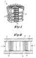
- Figure 1 represents an elastic springy element 1 which consists of a round tubular body 2 of springy foam which is provided in its wall with a series of almost lozenge-shaped holes 3 which are arranged according to a suitable pattern, and of a wire spring 4 which is located in the central cavity of the body.
- the springy foam can be synthetic foam, such as for instance polyurethane foam, or can be natural foam, such as for instance natural latex.
- the lozenge-shaped holes 3 extend from the outside inwards and the area of their cross-section decreases from a maximal value at the outside of the body 2 to almost zero at the inside. These holes 3 can, as represented in figure 1, be spread over the entire surface of the wall of the tubular body 2. However, they can also only be spread over part of this surface.
- the size of the holes 3 and the thickness of the wall of the body 2 and the diameter of the body 2 are chosen in function of the desired springy properties, taking into account the characteristics of the wire spring 4.
- the wire spring 4 is preferably made of steel but it can also be manufactured from synthetic material, for instance so-called composite materials. This wire spring is for instance round with a largest diameter which corresponds with the inner diameter of the body 2 so that this wire spring 4 fits closely to the inside of the body 2. However, the wire spring 4 can also be oblong, rectangular or square. The length of the wire spring 4 is preferably equal to the length of the body 2, whereby the wire spring 4 is pre-tensioned or not.
- the wire spring 4 can have different diameters or cross-sections, wire thicknesses or number of coils.
- the wire spring 4 can be a classic spiral spring as well as of a different type such as a cylindrical spring, a so-called offset spring or a so-called Bonnell spring.
- the wire spring 4 can be packed in a textile bag of wrapper which can be attached to the body 2, for instance glued thereto.
- the spring characteristics are improved by the combination.
- the impression resistance of a classic steel spring has a rather steep path, which means that the resistance of the spring with a given impression force increases rather rapidly.
- the combined springy element 1 according to figure 1 allows that, for an equal resistance, a larger wire spring with more coils is used, as the body 2 also intercepts part of the resistance, so that, upon impression, a much more equal path of the built-up resistance is obtained. This also causes a better slowing down or damping of the "after-springing", which is typical for a steel spring.
- It is a known phenomenon that a classic wire spring of steel has a tendency to move a large number of times up and down when suddenly impressed, which is very annoying when using the spring in a matress. With the combined Springy element 1 according to figure 1, this phenomenon is intercepted for 70 to 80% by the foam body 2 which, due to its cellular structure, can almost totally intercept the released energy.
- the combined springy element 1 offers additional advantages when it is used in a springy supporting element as represented in figure 2, consisting of two layers 5, of a springy material such as natural or synthetic foam, which are connected to each other by means of springy elements 1.
- a springy supporting element as represented in figure 2, consisting of two layers 5, of a springy material such as natural or synthetic foam, which are connected to each other by means of springy elements 1.
- Such supporting elements can form the inside of a matress, a cushion, the seat or the back of a piece of sitting or lying furniture etc.
- the wire springs 4 need no longer be interconnected to form a stable core as this is the case with classic steel springs. Indeed, the foam body 2 with the combined springy elements 1 serves as a housing for the steel spring and this body 2 has been glued without problems to the layers 5.
- the combined springy elements 1 have almost no resistance to the air circulation which should preferably occur in the supporting element in order to obtain a good micro-climate in the supporting element and a good moisture discharge.
- the holes in the foam body need not have a lozenge-shaped cross-section.
Landscapes
- Engineering & Computer Science (AREA)
- General Engineering & Computer Science (AREA)
- Mechanical Engineering (AREA)
- Mattresses And Other Support Structures For Chairs And Beds (AREA)
- Springs (AREA)
- Clamps And Clips (AREA)
Claims (10)
- Elément résilient élastique qui comprend un corps tubulaire en mousse (2) qui est muni de trous (3) s'étendant de l'extérieur vers l'intérieur, caractérisé en ce qu'il comprend un ressort (4) en fil métallique qui est entouré par le corps (2).
- Elément résilient élastique selon la revendication précédente, caractérisé en ce que le ressort (4) en fil métallique est un ressort appartenant au groupe formé par un ressort en spirale, un ressort cylindrique, ce que l'on appelle un ressort Bonnell ou ce que l'on appelle un ressort désaxé ou analogues.
- Elément résilient élastique selon l'une quelconque des revendications précédentes, caractérisé en ce que le ressort (4) en fil métallique est un ressort en fil métallique d'acier.
- Elément résilient élastique selon l'une quelconque des revendications 1 et 2, caractérisé en ce que le ressort (4) en fil métallique est réalisé en une matière synthétique.
- Elément résilient élastique selon l'une quelconque des revendications précédentes, caractérisé en ce que l'intérieur du corps tubulaire en mousse (2) est rond et en ce que le ressort (4) en fil métallique est également rond, le diamètre maximal du ressort correspondant au diamètre interne du corps (2).
- Elément résilient élastique selon l'une quelconque des revendications précédentes, caractérisé en ce que la longueur du ressort (4) en fil métallique dans la position de repos est égale à la longueur du corps tubulaire (2) dans la position de repos.
- Elément résilient élastique selon l'une quelconque des revendications 1 à 5, caractérisé en ce que la longueur du ressort (4) en fil métallique dans la position de repos est supérieure à la longueur du corps tubulaire (2) dans la position de repos.
- Elément résilient élastique selon la revendication 7, caractérisé en ce que le ressort (4) en fil métallique est soumis à une prétension qui réduit sa longueur pour la rendre égale à celle du corps tubulaire (2) dans la position de repos.
- Elément résilient élastique selon l'une quelconque des revendications précédentes, caractérisé en ce que les trous (3) pratiqués dans le corps (2) possèdent un diamètre qui diminue depuis une valeur maximale à l'extérieur du corps jusqu'à approximativement zéro à l'intérieur.
- Elément de support résilient qui comprend deux couches (5) d'une matière résiliente entre lesquelles sont disposés des éléments résilients élastiques (1), caractérisé en ce que ces éléments résilients (1) comprennent un corps tubulaire en mousse (2) qui est muni de trous (3) s'étendant de l'extérieur vers l'intérieur et comprennent un ressort (4) en fil métallique à l'intérieur de ce corps (2), les corps (2) de ces éléments résilients (1) étant collés aux couches (5) de la matière résiliente.
Applications Claiming Priority (2)
| Application Number | Priority Date | Filing Date | Title |
|---|---|---|---|
| BE9300501 | 1993-05-14 | ||
| BE9300501A BE1007171A3 (nl) | 1993-05-14 | 1993-05-14 | Elastisch verend element en verend steunelement voorzien van dergelijke elastisch verende elementen. |
Publications (2)
| Publication Number | Publication Date |
|---|---|
| EP0624332A1 EP0624332A1 (fr) | 1994-11-17 |
| EP0624332B1 true EP0624332B1 (fr) | 1998-03-04 |
Family
ID=3887048
Family Applications (1)
| Application Number | Title | Priority Date | Filing Date |
|---|---|---|---|
| EP19940201266 Expired - Lifetime EP0624332B1 (fr) | 1993-05-14 | 1994-05-06 | Elément de ressort élastique et élément de support élastique pourvu de tels éléments de ressort |
Country Status (7)
| Country | Link |
|---|---|
| EP (1) | EP0624332B1 (fr) |
| BE (1) | BE1007171A3 (fr) |
| CA (1) | CA2123554A1 (fr) |
| DE (1) | DE69408714T2 (fr) |
| DK (1) | DK0624332T3 (fr) |
| ES (1) | ES2114127T3 (fr) |
| PL (1) | PL174504B1 (fr) |
Cited By (1)
| Publication number | Priority date | Publication date | Assignee | Title |
|---|---|---|---|---|
| CN100488412C (zh) * | 2003-08-27 | 2009-05-20 | 伊姆赫德股份有限公司 | 床垫芯及用于床垫芯的组合弹簧的制造方法 |
Families Citing this family (21)
| Publication number | Priority date | Publication date | Assignee | Title |
|---|---|---|---|---|
| BE1009544A3 (nl) * | 1995-08-16 | 1997-05-06 | Imhold Naamloze Vennootschap | Samengesteld elastisch verend element en verend steunelement voorzien van dergelijke verende elementen. |
| BE1011070A3 (nl) * | 1997-03-27 | 1999-04-06 | Imhold Naamloze Vennootschap | Schuimveer. |
| FR2772261B1 (fr) * | 1997-12-11 | 2000-03-03 | Snc Oniewski Meiller Medical 2 | Matelas anti-escarres perfectionne |
| BE1012627A3 (nl) | 1999-04-23 | 2001-01-09 | Imhold Nv | Hoofdkussen. |
| US6347423B1 (en) * | 2000-09-29 | 2002-02-19 | Sidhil Technology, Llc | Jacketed cushioning elements and assemblies thereof in mattresses and upholstery |
| BE1014277A3 (nl) * | 2001-07-04 | 2003-07-01 | Imhold Nv | Werkwijze voor het vervaardigen van een vulelement. |
| RU2194429C1 (ru) * | 2001-12-14 | 2002-12-20 | Артамонов Николай Вячеславович | Упругий блок для мягкой мебели |
| FR2883462B1 (fr) * | 2005-03-25 | 2007-06-22 | Cie Financiere Europ De Literi | Matelas a ressorts ensaches |
| CN100506117C (zh) * | 2005-06-20 | 2009-07-01 | 廖秀真 | 组合式床垫 |
| US8266745B2 (en) | 2007-02-07 | 2012-09-18 | L&P Property Management Company | Slow acting pocketed spring core having fill material inside pockets |
| US8474078B2 (en) | 2007-02-07 | 2013-07-02 | L&P Property Management Company | Slow acting pocketed spring core having cushioning material |
| US7636972B2 (en) | 2007-02-07 | 2009-12-29 | L&P Property Management Company | Slow acting pocketed spring core |
| US9072390B2 (en) | 2007-08-21 | 2015-07-07 | Elisana S.A.R.L. | Method for manufacturing a foam spring for pillow, cushion, mattresses, or the like |
| US10920842B2 (en) | 2007-09-21 | 2021-02-16 | Elisana S.A.R.L. | Foam spring for pillows, cushions, mattresses or the like and method for manufacturing such a foam spring |
| US8746662B2 (en) * | 2007-10-23 | 2014-06-10 | Elisna S.A.R.L. | Foam spring for pillows, cushions, mattresses or the like and method for manufacturing such a foam spring |
| DE202008002110U1 (de) * | 2008-01-11 | 2009-06-25 | Recticel Schlafkomfort Gmbh | Auflagekonstruktion für eine Matratze |
| US8353501B2 (en) | 2009-04-24 | 2013-01-15 | Willy Poppe | Foam spring for pillows, cushions, mattresses or the like and a method for manufacturing such a foam spring |
| DE202009016130U1 (de) | 2009-11-26 | 2010-04-08 | Fränkische Schlafmanufaktur Zagefka GmbH | Metallfreies Schaumstofffederelement für Matratzen, Polsterungen von Sitzmöbeln, Auflagen für Wasserbetten |
| RU182427U1 (ru) * | 2018-04-02 | 2018-08-16 | Олег Владимирович Гребенюк | Матрас |
| LU100788B1 (en) * | 2018-04-27 | 2019-10-28 | Variowell Dev Gmbh | A shaped body made from a foam and springs as well as uses thereof |
| CN110101238A (zh) * | 2019-03-22 | 2019-08-09 | 刘长权 | 一种弹性连接组件及具有该组件的弹性家具 |
Family Cites Families (4)
| Publication number | Priority date | Publication date | Assignee | Title |
|---|---|---|---|---|
| US2925856A (en) * | 1958-04-15 | 1960-02-23 | Nachman Corp | Cushion formed of foamed material and metal members |
| BE859468A (nl) * | 1977-10-07 | 1978-04-07 | Poppe Willy | Schuimveer |
| US5040255A (en) * | 1990-06-06 | 1991-08-20 | Barber Manufacturing Company, Inc. | Cushion or mattress structure |
| CA2049132A1 (fr) * | 1991-03-22 | 1992-09-23 | Phillip J. Pisczak | Matelas a ressorts et autres elements de support et procede de fabrication |
-
1993
- 1993-05-14 BE BE9300501A patent/BE1007171A3/nl not_active IP Right Cessation
-
1994
- 1994-05-06 ES ES94201266T patent/ES2114127T3/es not_active Expired - Lifetime
- 1994-05-06 DE DE1994608714 patent/DE69408714T2/de not_active Expired - Lifetime
- 1994-05-06 EP EP19940201266 patent/EP0624332B1/fr not_active Expired - Lifetime
- 1994-05-06 DK DK94201266T patent/DK0624332T3/da active
- 1994-05-13 CA CA 2123554 patent/CA2123554A1/fr not_active Abandoned
- 1994-05-13 PL PL94303442A patent/PL174504B1/pl not_active IP Right Cessation
Cited By (1)
| Publication number | Priority date | Publication date | Assignee | Title |
|---|---|---|---|---|
| CN100488412C (zh) * | 2003-08-27 | 2009-05-20 | 伊姆赫德股份有限公司 | 床垫芯及用于床垫芯的组合弹簧的制造方法 |
Also Published As
| Publication number | Publication date |
|---|---|
| EP0624332A1 (fr) | 1994-11-17 |
| DE69408714T2 (de) | 1998-10-01 |
| CA2123554A1 (fr) | 1994-11-15 |
| ES2114127T3 (es) | 1998-05-16 |
| PL174504B1 (pl) | 1998-08-31 |
| DK0624332T3 (da) | 1998-11-30 |
| DE69408714D1 (de) | 1998-04-09 |
| BE1007171A3 (nl) | 1995-04-11 |
Similar Documents
| Publication | Publication Date | Title |
|---|---|---|
| EP0624332B1 (fr) | Elément de ressort élastique et élément de support élastique pourvu de tels éléments de ressort | |
| EP0973423B1 (fr) | Blocs-ressorts | |
| US6523812B1 (en) | Spring units | |
| US3280410A (en) | Multi-directional molded spring assembly | |
| US6128798A (en) | Cavitated pad and innerspring assembly combination having springs with free terminal convolutions | |
| US6658682B1 (en) | Bedding or seating product with spring core topper | |
| US7210181B1 (en) | Spring construction | |
| US5687439A (en) | Border stabilizing member and innerspring assembly using same | |
| US3716874A (en) | Differentially resilient spring assembly | |
| US5327596A (en) | Combination spring/foam cushioning | |
| US20110148018A1 (en) | Asymmetrical combined cylindrical and conical springs | |
| US11103083B2 (en) | Comfort layer having pocketed springs of different heights | |
| MX2007002292A (es) | Componentes de muelles asimetricos y muelles internos para colchones de un solo lado. | |
| US3720966A (en) | Spring upholstery cushioning | |
| US11033115B2 (en) | Comfort layer having repeating pattern of pocketed mini coil springs of different heights | |
| WO2020185307A1 (fr) | Couche de confort dotée de ressorts ensachés à espacement | |
| EP0793932B1 (fr) | Elément de ressort élastique et support à ressort comportant de tels éléments de ressort élastique | |
| US3430275A (en) | Dual firmness spring for bedding and the like | |
| EP0762011A1 (fr) | Elément de ressort élastique composite et élément de support élastique pourvu de tels éléments de ressort | |
| US2617124A (en) | Spring unit for mattresses, cushions, and the like | |
| EP3400844A1 (fr) | Noyau de ressort à ressort ensaché et ressorts en mousse | |
| AU1988599A (en) | Spring mattress | |
| RU2215458C2 (ru) | Пружинный матрац | |
| CA2049132A1 (fr) | Matelas a ressorts et autres elements de support et procede de fabrication | |
| CA2068620C (fr) | Assemblage de matelas |
Legal Events
| Date | Code | Title | Description |
|---|---|---|---|
| PUAI | Public reference made under article 153(3) epc to a published international application that has entered the european phase |
Free format text: ORIGINAL CODE: 0009012 |
|
| AK | Designated contracting states |
Kind code of ref document: A1 Designated state(s): BE DE DK ES FR GB IT NL SE |
|
| 17P | Request for examination filed |
Effective date: 19950513 |
|
| 17Q | First examination report despatched |
Effective date: 19960410 |
|
| GRAG | Despatch of communication of intention to grant |
Free format text: ORIGINAL CODE: EPIDOS AGRA |
|
| GRAG | Despatch of communication of intention to grant |
Free format text: ORIGINAL CODE: EPIDOS AGRA |
|
| GRAH | Despatch of communication of intention to grant a patent |
Free format text: ORIGINAL CODE: EPIDOS IGRA |
|
| GRAH | Despatch of communication of intention to grant a patent |
Free format text: ORIGINAL CODE: EPIDOS IGRA |
|
| GRAA | (expected) grant |
Free format text: ORIGINAL CODE: 0009210 |
|
| AK | Designated contracting states |
Kind code of ref document: B1 Designated state(s): BE DE DK ES FR GB IT NL SE |
|
| REF | Corresponds to: |
Ref document number: 69408714 Country of ref document: DE Date of ref document: 19980409 |
|
| ITF | It: translation for a ep patent filed | ||
| REG | Reference to a national code |
Ref country code: ES Ref legal event code: FG2A Ref document number: 2114127 Country of ref document: ES Kind code of ref document: T3 |
|
| ET | Fr: translation filed | ||
| REG | Reference to a national code |
Ref country code: DK Ref legal event code: T3 |
|
| PLBE | No opposition filed within time limit |
Free format text: ORIGINAL CODE: 0009261 |
|
| STAA | Information on the status of an ep patent application or granted ep patent |
Free format text: STATUS: NO OPPOSITION FILED WITHIN TIME LIMIT |
|
| 26N | No opposition filed | ||
| REG | Reference to a national code |
Ref country code: GB Ref legal event code: IF02 |
|
| PG25 | Lapsed in a contracting state [announced via postgrant information from national office to epo] |
Ref country code: IT Free format text: LAPSE BECAUSE OF NON-PAYMENT OF DUE FEES Effective date: 20050506 |
|
| PGFP | Annual fee paid to national office [announced via postgrant information from national office to epo] |
Ref country code: ES Payment date: 20080509 Year of fee payment: 15 Ref country code: DK Payment date: 20080523 Year of fee payment: 15 |
|
| PGFP | Annual fee paid to national office [announced via postgrant information from national office to epo] |
Ref country code: SE Payment date: 20080508 Year of fee payment: 15 |
|
| PGFP | Annual fee paid to national office [announced via postgrant information from national office to epo] |
Ref country code: GB Payment date: 20080520 Year of fee payment: 15 |
|
| REG | Reference to a national code |
Ref country code: DK Ref legal event code: EBP |
|
| GBPC | Gb: european patent ceased through non-payment of renewal fee |
Effective date: 20090506 |
|
| PG25 | Lapsed in a contracting state [announced via postgrant information from national office to epo] |
Ref country code: DK Free format text: LAPSE BECAUSE OF NON-PAYMENT OF DUE FEES Effective date: 20090531 |
|
| PG25 | Lapsed in a contracting state [announced via postgrant information from national office to epo] |
Ref country code: GB Free format text: LAPSE BECAUSE OF NON-PAYMENT OF DUE FEES Effective date: 20090506 |
|
| REG | Reference to a national code |
Ref country code: ES Ref legal event code: FD2A Effective date: 20090507 |
|
| PGFP | Annual fee paid to national office [announced via postgrant information from national office to epo] |
Ref country code: FR Payment date: 20100519 Year of fee payment: 17 |
|
| PGFP | Annual fee paid to national office [announced via postgrant information from national office to epo] |
Ref country code: NL Payment date: 20100531 Year of fee payment: 17 Ref country code: DE Payment date: 20100511 Year of fee payment: 17 |
|
| PG25 | Lapsed in a contracting state [announced via postgrant information from national office to epo] |
Ref country code: ES Free format text: LAPSE BECAUSE OF NON-PAYMENT OF DUE FEES Effective date: 20090507 |
|
| PGFP | Annual fee paid to national office [announced via postgrant information from national office to epo] |
Ref country code: BE Payment date: 20100428 Year of fee payment: 17 |
|
| PG25 | Lapsed in a contracting state [announced via postgrant information from national office to epo] |
Ref country code: SE Free format text: LAPSE BECAUSE OF NON-PAYMENT OF DUE FEES Effective date: 20090507 |
|
| PGFP | Annual fee paid to national office [announced via postgrant information from national office to epo] |
Ref country code: IT Payment date: 20100504 Year of fee payment: 17 |
|
| PGRI | Patent reinstated in contracting state [announced from national office to epo] |
Ref country code: IT Effective date: 20110616 |
|
| BERE | Be: lapsed |
Owner name: *IMHOLD N.V. Effective date: 20110531 |
|
| REG | Reference to a national code |
Ref country code: DE Ref legal event code: R119 Ref document number: 69408714 Country of ref document: DE |
|
| REG | Reference to a national code |
Ref country code: DE Ref legal event code: R119 Ref document number: 69408714 Country of ref document: DE |
|
| REG | Reference to a national code |
Ref country code: NL Ref legal event code: V1 Effective date: 20111201 |
|
| PG25 | Lapsed in a contracting state [announced via postgrant information from national office to epo] |
Ref country code: NL Free format text: LAPSE BECAUSE OF NON-PAYMENT OF DUE FEES Effective date: 20111201 |
|
| REG | Reference to a national code |
Ref country code: FR Ref legal event code: ST Effective date: 20120131 |
|
| PGRI | Patent reinstated in contracting state [announced from national office to epo] |
Ref country code: IT Effective date: 20110616 |
|
| PG25 | Lapsed in a contracting state [announced via postgrant information from national office to epo] |
Ref country code: BE Free format text: LAPSE BECAUSE OF NON-PAYMENT OF DUE FEES Effective date: 20110531 |
|
| PG25 | Lapsed in a contracting state [announced via postgrant information from national office to epo] |
Ref country code: FR Free format text: LAPSE BECAUSE OF NON-PAYMENT OF DUE FEES Effective date: 20110531 |
|
| PG25 | Lapsed in a contracting state [announced via postgrant information from national office to epo] |
Ref country code: DE Free format text: LAPSE BECAUSE OF NON-PAYMENT OF DUE FEES Effective date: 20111130 |