EP0624465A1 - Dispositif de prescellage d'un document sur un bande plastique - Google Patents
Dispositif de prescellage d'un document sur un bande plastique Download PDFInfo
- Publication number
- EP0624465A1 EP0624465A1 EP19940400668 EP94400668A EP0624465A1 EP 0624465 A1 EP0624465 A1 EP 0624465A1 EP 19940400668 EP19940400668 EP 19940400668 EP 94400668 A EP94400668 A EP 94400668A EP 0624465 A1 EP0624465 A1 EP 0624465A1
- Authority
- EP
- European Patent Office
- Prior art keywords
- cylinder
- document
- documents
- plastic strip
- cutting
- Prior art date
- Legal status (The legal status is an assumption and is not a legal conclusion. Google has not performed a legal analysis and makes no representation as to the accuracy of the status listed.)
- Granted
Links
- 229920003023 plastic Polymers 0.000 title claims abstract description 44
- 239000004033 plastic Substances 0.000 title claims abstract description 44
- 238000007789 sealing Methods 0.000 title 1
- 238000010438 heat treatment Methods 0.000 claims abstract description 24
- 238000000605 extraction Methods 0.000 claims description 13
- 238000003825 pressing Methods 0.000 claims description 3
- 238000004804 winding Methods 0.000 claims 1
- 239000002184 metal Substances 0.000 description 4
- 230000008021 deposition Effects 0.000 description 3
- 230000004913 activation Effects 0.000 description 2
- 238000007664 blowing Methods 0.000 description 2
- 238000010030 laminating Methods 0.000 description 2
- 239000004698 Polyethylene Substances 0.000 description 1
- 229910000831 Steel Inorganic materials 0.000 description 1
- 239000000853 adhesive Substances 0.000 description 1
- 238000004026 adhesive bonding Methods 0.000 description 1
- 230000001070 adhesive effect Effects 0.000 description 1
- 230000003190 augmentative effect Effects 0.000 description 1
- 230000002452 interceptive effect Effects 0.000 description 1
- 238000000034 method Methods 0.000 description 1
- 229920000728 polyester Polymers 0.000 description 1
- -1 polyethylene Polymers 0.000 description 1
- 229920000573 polyethylene Polymers 0.000 description 1
- 230000001105 regulatory effect Effects 0.000 description 1
- 239000010959 steel Substances 0.000 description 1
- 230000001360 synchronised effect Effects 0.000 description 1
Images


Classifications
-
- B—PERFORMING OPERATIONS; TRANSPORTING
- B32—LAYERED PRODUCTS
- B32B—LAYERED PRODUCTS, i.e. PRODUCTS BUILT-UP OF STRATA OF FLAT OR NON-FLAT, e.g. CELLULAR OR HONEYCOMB, FORM
- B32B37/00—Methods or apparatus for laminating, e.g. by curing or by ultrasonic bonding
- B32B37/02—Methods or apparatus for laminating, e.g. by curing or by ultrasonic bonding characterised by a sequence of laminating steps, e.g. by adding new layers at consecutive laminating stations
-
- B—PERFORMING OPERATIONS; TRANSPORTING
- B26—HAND CUTTING TOOLS; CUTTING; SEVERING
- B26D—CUTTING; DETAILS COMMON TO MACHINES FOR PERFORATING, PUNCHING, CUTTING-OUT, STAMPING-OUT OR SEVERING
- B26D1/00—Cutting through work characterised by the nature or movement of the cutting member or particular materials not otherwise provided for; Apparatus or machines therefor; Cutting members therefor
- B26D1/01—Cutting through work characterised by the nature or movement of the cutting member or particular materials not otherwise provided for; Apparatus or machines therefor; Cutting members therefor involving a cutting member which does not travel with the work
- B26D1/12—Cutting through work characterised by the nature or movement of the cutting member or particular materials not otherwise provided for; Apparatus or machines therefor; Cutting members therefor involving a cutting member which does not travel with the work having a cutting member moving about an axis
- B26D1/14—Cutting through work characterised by the nature or movement of the cutting member or particular materials not otherwise provided for; Apparatus or machines therefor; Cutting members therefor involving a cutting member which does not travel with the work having a cutting member moving about an axis with a circular cutting member, e.g. disc cutter
- B26D1/22—Cutting through work characterised by the nature or movement of the cutting member or particular materials not otherwise provided for; Apparatus or machines therefor; Cutting members therefor involving a cutting member which does not travel with the work having a cutting member moving about an axis with a circular cutting member, e.g. disc cutter coacting with a movable member, e.g. a roller
- B26D1/225—Cutting through work characterised by the nature or movement of the cutting member or particular materials not otherwise provided for; Apparatus or machines therefor; Cutting members therefor involving a cutting member which does not travel with the work having a cutting member moving about an axis with a circular cutting member, e.g. disc cutter coacting with a movable member, e.g. a roller for thin material, e.g. for sheets, strips or the like
-
- B—PERFORMING OPERATIONS; TRANSPORTING
- B26—HAND CUTTING TOOLS; CUTTING; SEVERING
- B26D—CUTTING; DETAILS COMMON TO MACHINES FOR PERFORATING, PUNCHING, CUTTING-OUT, STAMPING-OUT OR SEVERING
- B26D7/00—Details of apparatus for cutting, cutting-out, stamping-out, punching, perforating, or severing by means other than cutting
- B26D7/27—Means for performing other operations combined with cutting
-
- B—PERFORMING OPERATIONS; TRANSPORTING
- B32—LAYERED PRODUCTS
- B32B—LAYERED PRODUCTS, i.e. PRODUCTS BUILT-UP OF STRATA OF FLAT OR NON-FLAT, e.g. CELLULAR OR HONEYCOMB, FORM
- B32B37/00—Methods or apparatus for laminating, e.g. by curing or by ultrasonic bonding
- B32B37/04—Methods or apparatus for laminating, e.g. by curing or by ultrasonic bonding characterised by the partial melting of at least one layer
-
- B—PERFORMING OPERATIONS; TRANSPORTING
- B32—LAYERED PRODUCTS
- B32B—LAYERED PRODUCTS, i.e. PRODUCTS BUILT-UP OF STRATA OF FLAT OR NON-FLAT, e.g. CELLULAR OR HONEYCOMB, FORM
- B32B37/00—Methods or apparatus for laminating, e.g. by curing or by ultrasonic bonding
- B32B37/14—Methods or apparatus for laminating, e.g. by curing or by ultrasonic bonding characterised by the properties of the layers
- B32B37/16—Methods or apparatus for laminating, e.g. by curing or by ultrasonic bonding characterised by the properties of the layers with all layers existing as coherent layers before laminating
- B32B37/22—Methods or apparatus for laminating, e.g. by curing or by ultrasonic bonding characterised by the properties of the layers with all layers existing as coherent layers before laminating involving the assembly of both discrete and continuous layers
- B32B37/223—One or more of the layers being plastic
- B32B37/226—Laminating sheets, panels or inserts between two continuous plastic layers
-
- B—PERFORMING OPERATIONS; TRANSPORTING
- B32—LAYERED PRODUCTS
- B32B—LAYERED PRODUCTS, i.e. PRODUCTS BUILT-UP OF STRATA OF FLAT OR NON-FLAT, e.g. CELLULAR OR HONEYCOMB, FORM
- B32B38/00—Ancillary operations in connection with laminating processes
- B32B38/18—Handling of layers or the laminate
- B32B38/1825—Handling of layers or the laminate characterised by the control or constructional features of devices for tensioning, stretching or registration
- B32B38/1833—Positioning, e.g. registration or centering
-
- B—PERFORMING OPERATIONS; TRANSPORTING
- B32—LAYERED PRODUCTS
- B32B—LAYERED PRODUCTS, i.e. PRODUCTS BUILT-UP OF STRATA OF FLAT OR NON-FLAT, e.g. CELLULAR OR HONEYCOMB, FORM
- B32B2317/00—Animal or vegetable based
- B32B2317/12—Paper, e.g. cardboard
-
- B—PERFORMING OPERATIONS; TRANSPORTING
- B32—LAYERED PRODUCTS
- B32B—LAYERED PRODUCTS, i.e. PRODUCTS BUILT-UP OF STRATA OF FLAT OR NON-FLAT, e.g. CELLULAR OR HONEYCOMB, FORM
- B32B2323/00—Polyalkenes
- B32B2323/04—Polyethylene
-
- B—PERFORMING OPERATIONS; TRANSPORTING
- B32—LAYERED PRODUCTS
- B32B—LAYERED PRODUCTS, i.e. PRODUCTS BUILT-UP OF STRATA OF FLAT OR NON-FLAT, e.g. CELLULAR OR HONEYCOMB, FORM
- B32B2425/00—Cards, e.g. identity cards, credit cards
-
- Y—GENERAL TAGGING OF NEW TECHNOLOGICAL DEVELOPMENTS; GENERAL TAGGING OF CROSS-SECTIONAL TECHNOLOGIES SPANNING OVER SEVERAL SECTIONS OF THE IPC; TECHNICAL SUBJECTS COVERED BY FORMER USPC CROSS-REFERENCE ART COLLECTIONS [XRACs] AND DIGESTS
- Y10—TECHNICAL SUBJECTS COVERED BY FORMER USPC
- Y10T—TECHNICAL SUBJECTS COVERED BY FORMER US CLASSIFICATION
- Y10T156/00—Adhesive bonding and miscellaneous chemical manufacture
- Y10T156/12—Surface bonding means and/or assembly means with cutting, punching, piercing, severing or tearing
- Y10T156/1317—Means feeding plural workpieces to be joined
- Y10T156/1322—Severing before bonding or assembling of parts
- Y10T156/133—Delivering cut part to indefinite or running length web
-
- Y—GENERAL TAGGING OF NEW TECHNOLOGICAL DEVELOPMENTS; GENERAL TAGGING OF CROSS-SECTIONAL TECHNOLOGIES SPANNING OVER SEVERAL SECTIONS OF THE IPC; TECHNICAL SUBJECTS COVERED BY FORMER USPC CROSS-REFERENCE ART COLLECTIONS [XRACs] AND DIGESTS
- Y10—TECHNICAL SUBJECTS COVERED BY FORMER USPC
- Y10T—TECHNICAL SUBJECTS COVERED BY FORMER US CLASSIFICATION
- Y10T156/00—Adhesive bonding and miscellaneous chemical manufacture
- Y10T156/17—Surface bonding means and/or assemblymeans with work feeding or handling means
- Y10T156/1702—For plural parts or plural areas of single part
- Y10T156/1712—Indefinite or running length work
- Y10T156/1734—Means bringing articles into association with web
-
- Y—GENERAL TAGGING OF NEW TECHNOLOGICAL DEVELOPMENTS; GENERAL TAGGING OF CROSS-SECTIONAL TECHNOLOGIES SPANNING OVER SEVERAL SECTIONS OF THE IPC; TECHNICAL SUBJECTS COVERED BY FORMER USPC CROSS-REFERENCE ART COLLECTIONS [XRACs] AND DIGESTS
- Y10—TECHNICAL SUBJECTS COVERED BY FORMER USPC
- Y10T—TECHNICAL SUBJECTS COVERED BY FORMER US CLASSIFICATION
- Y10T83/00—Cutting
- Y10T83/202—With product handling means
- Y10T83/2074—Including means to divert one portion of product from another
- Y10T83/2087—Diverging product movers
Definitions
- the present invention relates to a device for prescoring a document on a plastic strip. It applies in particular to the laminating of original documents such as identity cards or any other identification documents for example. More generally, it applies to the laminating of documents whose state it is necessary to save for reasons of security or reliability.
- the quality of plasticization of identification documents contributes in particular to the security and reliability that these must provide. Different criteria help define this quality. Among these, the regularity of the plastic edges plays an important role. It is indeed important that the document, an identification card of rectangular shape for example, is well centered in the middle of the plastic rectangle covering it, for reasons of automatic recognition or reliability of the document for example. For this purpose, when the document is previously placed on a plastic strip, it must be perfectly positioned on the latter, in particular with respect to the cutting line of the assembly consisting of the document and the plastic strip, this is that is, the laminated document.
- plasticization techniques consist in unwinding a first plastic strip on which the document to be laminated is deposited, the assembly then being covered with a second plastic strip on the opposite side of the document to the first strip, the following operations generally consisting of heating the strips on the surface of the document to fix them definitively then cutting the document thus plasticized.
- a plastic edge is left around the document or the cut is made just at the edge of the document for example. In both cases, it is necessary to correctly position the document on the first plastic strip relative to its cutting line, in particular to obtain regular edges.
- a fixing can be obtained for example by a heating point or by a point of adhesive on the strip at the level of the document.
- attachment point or points are perfectly positioned relative to the document to prevent a drift in positioning the attachment point at the as the documents scroll, this or these attachment points are located outside the document and therefore they are not fixed.
- the object of the invention is to allow pre-stacking of documents on a plastic strip at the time of their deposition thereon so that the position of the pre-stacking points on the documents remains perfectly stable.
- the main advantages of the invention are that it is suitable for devices plasticizing documents in large series, that it is suitable for all types of documents, that it is simple to implement and that it is economical.
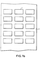
- FIG. 1a presents documents 1, for example of paper, to be laminated deposited on a plastic strip 2.
- the assembly is for example covered with a second plastic strip and then scrolls for example under means of heating these strips and under means for cutting plasticized documents.
- FIG. 1a presents, by way of example, three rows of documents 1 that are misaligned because they are not previously fixed to the strip when they are deposited thereon, this misalignment being for example due to the movement of the strip or to the environment outside.
- FIG. 1b presents documents 1 suitably aligned on the plastic strip 2, these having been fixed to the strip at the time of their deposition thereon, by means of heating points of the strip for example.
- the adhesion face of the strip made of polyethylene for example, being in contact with the document is fixed to the latter when it reaches a given temperature
- the opposite face of the strip made of polyester for example, being not sensitive heat only at a temperature significantly above this given temperature.
- the documents could also be fixed by gluing points for example.
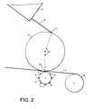
- FIG. 2 illustrates a first possible embodiment of a device according to the invention, which in particular makes it possible to fix the aforementioned documents 1 at the time of their deposition on the plastic strip 2.
- the device comprises at least a first cylinder 3 on which a document is wound from a point T1 in the space tangent to this first cylinder and means for fixing the plastic strip 2 at a point T2 tangent to the first cylinder 3, the two tangent points T1 and T2 making a constant angle ⁇ between them when they are taken relative to the center of the first cylinder 3.
- the document is for example previously stored in a store 5 and then brought to the first tangent point T1 mentioned above by a guide 6.
- the first cylinder 3 has for example a continuous and constant speed of rotation.
- the fixing means are for example heating means consisting of a metal part 4 heated by an electrical resistance, the temperature of the metal part being for example regulated at a given level.
- the movements or the activation of the heating means 4 are adjusted so that when a given point of the document passes at the level of the second tangent point T2, these heating means 4 fix the document on the strip 2 at this point given by heat that they release on this strip 2 at this point. Knowing the speed of the first cylinder 3 and the instant when the document begins to wind on the cylinder, it is possible to adjust the movements or the activation of the heating means so that they fix the document at the desired point.
- the heating means 4 heated metal parts for example, are for example fixed on a second cylinder 7 rotating for example at the same speed as the first cylinder 3, so as to heat the plastic strip 2 at the second tangent point T2 when the given point of the document at which the fixing is to be carried out passes over this second tangent point T2.
- the second cylinder may contain, for example, several heating means 4 on its periphery. Rotating at the same speed as the first cylinder, it can also support several heating means if several documents are wound around the first cylinder, the number of heating means 4 being equal to the number of documents located between these two points.
- the second cylinder having for example only one heated metal part, can rotate at a speed N times greater than that of the first cylinder.
- the initial angular position of the second cylinder must be well defined relative to the second tangent point T2 on the one hand, and the relative angular velocities of the two cylinders 3, 7 must be well defined between them on the other hand. They are therefore functions of each other.
- the fixing means constituted by way of example by the heating means 4 could also consist in particular of bonding means.
- the document When the document reaches the first cylinder 3 at the first tangent point T1, the document is for example attached to the first cylinder 3 by a cleat. It is for example kept pressed against the surface of the first cylinder 3 by a suction system.
- the surface of the cylinder is for example made up of a certain number of holes or lead to suction conduits creating a vacuum where they are covered with the document.
- These same conduits are used for example to deposit the document on the strip 2 by replacing the suction with the air blowing. This blowing can also be used to cool the first cylinder 3 heated by the fixing means or remove stains for example.
- the plastic strip 2 is for example previously wound around a third cylinder 8 from which it is then unwound.
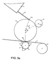
- FIG. 3a shows another possible embodiment of a device according to the invention applied in particular to a case where one or more documents are pre-printed on a sheet, the document or documents having to be cut from the sheet.
- a cutting cylinder 9 With the preceding cylinders 3, 7 is associated a cutting cylinder 9, a sectional view of which is presented in FIG. 3b. In this view, it is shown in contact with the first cylinder 3, also shown in section.
- the center CD of the cutting cylinder 9 makes for example a constant angle ⁇ with the first tangent point T1.
- the cutting cylinder 9 has at least one cutting line 10, shown in section for cutting documents printed on a sheet wound around the first cylinder 3 from the first tangent point T1, the position of the printed documents being well defined relative to the first edge of the sheet meeting this tangent point T1.
- the document is cut by pressing the cutting cylinder 9 on the first cylinder 3, and more precisely by pressing the cutting line 10 on the leaf.
- the cutting line 10 is for example made up of steel threads with projecting endings. If the sheet contains several rows of documents to be cut and then laminated, the cutting cylinder 9 then contains, for example, as many cutting lines 10, 11, 12 as there are rows, three for example.
- the speeds of rotation of the first cylinder 3 and of the cutting cylinder 9 are synchronized so that the cutting line cuts the documents in the right places, their respective initial positions being moreover well defined.
- the gear ratio is also adjusted so that the documents included on the same sheet and in the same row are cut from the same cylinder turn.
- the cutting cylinder 9 rotates KxM faster than the first cylinder 3.
- the tangential speeds of the two cylinders are for example substantially identical at their respective circumferences.
- the position of the cutting line of the cutting cylinder 9 must be well defined relative to the moment when the sheets start to wind on the first cylinder 3.
- the rotational speeds of the two cylinders 3, 9 may for example be discontinuous, the first cylinder stopping before receiving a sheet. Then this being in abutment at the first tangent point T1, the first cylinder turns again when the angular position of the cutting cylinder reaches a given position, this position being defined so that the documents are cut in the right places of the sheet taking into account the respective speeds of the cylinders 3, 9.
- FIG. 4 shows the embodiment of FIG. 3 augmented with means for extracting the skeleton of each sheet from the first cylinder 3, in particular to prevent this skeleton from interfering with the plasticization of the cut documents, the skeleton being the remaining part of each sheet after cutting.
- These extraction means consist for example of a set of cylinders 41, 42, 43 and series of belts 44, 45, 46.
- a first extraction cylinder 41 drives a first series of belts 44 housed moreover in grooves of the first cylinder 3. These grooves are located so that the belts parallel to each other, of the first series 44, are located below unprinted areas therefore intended to be part of the skeleton of each sheet.
- the first extraction cylinder is positioned so that the belts 44 move away from the first cylinder 3 just after the documents have been cut, for example, this then makes it possible to move the skeleton of each sheet away from this first cylinder 3.
- a second series of belts 45 is superimposed on the documents after their cut to maintain these on the first cylinder.
- the belts are driven by the cutting cylinder 9 and by a second extraction cylinder 42, the latter being positioned so that the belts of the second series 45 suitably hold the documents at the cutting outlet.
- this second series contains for example a single belt.
- a third series of belts 46 for example moves the skeletons of the first series of belts away, the belts of this third series 46 being driven by the first extraction cylinder 41 and by a third extraction cylinder 43.
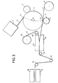
- FIG. 5 presents a device according to the invention produced according to a mode illustrated by the preceding figures and associated for example with a set of plasticizing and cutting of plasticized documents, the means for extracting the skeletons not having been shown.
- a second plastic strip 51 unwinds from a cylinder 52 to be superimposed on the first plastic strip 2 and on the documents pre-assembled on this first strip 2, at the level of the plasticizing means 53, 54 consisting for example of two heating parts 53 , 54. Each of the parts heats one of the strips 2, 51 in order to fix them on the documents.
- a cylinder 60 interposed for example between the cylinder 52 from which the second strip 51 takes place and the plasticizing means 53, 54 deflects this second strip 51 to allow it to enter the plasticizing means tangentially to the first strip 2.
- the two plastic strips and the documents are diverted by a set of three cylinders 55, 56, 57 to means of cutting 58, 59. The latter cut the plasticized documents.
- They consist, for example, of a punch 58 engaging in a cutting die 59. They include several punches if several plasticized documents are cut simultaneously. By playing on the position of one of the three cylinders 55, 56, 57 mentioned above, it is possible to adjust the position of the documents relative to the cutting line of the cutting means 58, 59.
- the prescasting of the documents on the first plastic strip 2 allows them to keep a fixed position thereon until they enter the plasticizing means 53, 54.
- a cutting system similar to that comprising the first cylinder 3 and the cutting cylinder 9 can for example replace the system 58, 59 for cutting the plastic cards described above.
Landscapes
- Life Sciences & Earth Sciences (AREA)
- Forests & Forestry (AREA)
- Engineering & Computer Science (AREA)
- Mechanical Engineering (AREA)
- Lining Or Joining Of Plastics Or The Like (AREA)
- Folding Of Thin Sheet-Like Materials, Special Discharging Devices, And Others (AREA)
- Labeling Devices (AREA)
- Collation Of Sheets And Webs (AREA)
- Basic Packing Technique (AREA)
- Processing And Handling Of Plastics And Other Materials For Molding In General (AREA)
Abstract
Description
- La présente invention concerne un dispositif de préscellage d'un document sur une bande plastique. Elle s'applique notamment à la plastification de documents originaux tels que des cartes d'identité ou tout autres documents d'identification par exemple. Plus généralement, elle s'applique à la plastification de documents dont il est nécessaire de sauvegarder l'état pour des raisons de sécurités ou de fiabilité.
- La qualité de plastification de documents d'identification participe notamment à la sécurité et à la fiabilité que doivent procurer ces derniers. Différents critères concourent à définir cette qualité. Parmi ceux-ci, la régularité des bords de plastique joue un rôle important. Il importe en effet que le document, une carte d'identification de forme rectangulaire par exemple, soit bien centré au milieu du rectangle de plastique le recouvrant, pour des raisons de reconnaissance automatique ou de fiabilité du document par exemple. A cet effet, quand le document est préalablement placé sur une bande en plastique, il doit être parfaitement positionné sur cette dernière, notamment par rapport à la ligne de découpe de l'ensemble constitué du document et de la bande en plastique, c'est-à-dire du document plastifié. En effet, la plupart des techniques de plastification consistent à dérouler une première bande en plastique sur laquelle est déposé le document à plastifier, l'ensemble étant ensuite recouvert d'une deuxième bande en plastique sur la face opposée du document à la première bande, les opérations suivantes consistant généralement à chauffer les bandes sur la surface du document pour les fixer définitivement puis à découper le document ainsi plastifié. Un bord en plastique est laissé autour du document ou la découpe est opérée juste au bord du document par exemple. Dans les deux cas, il est nécessaire de bien positionner le document sur la première bande en plastique par rapport à sa ligne de découpe notamment pour obtenir des bords réguliers. Or, entre la dépose du document sur la première bande en plastique et son passage au niveau de cette ligne de découpe ou du dispositif de chauffage des bandes fixant le document sur celles-ci, il y a un certain espacement, pour permettre par exemple le recouvrement du document par une deuxième bande en plastique. Cet espacement peut aussi être par exemple dû à l'encombrement des machines. Durant le trajet parcouru par un document sur la bande se déroulant, ce dernier risque donc de se déplacer sur la bande, donc de perdre sa position initiale et de se trouver mal positionné au moment du passage sous la ligne de découpe. En particulier, si plusieurs rangées de documents sont disposées sur la bande en plastique, ceux-ci risquent de se désaligner. Il est donc nécessaire de fixer le document sur la première bande en plastique au moment de sa dépose sur celle-ci. Cela permet notamment d'éviter que le document ne se déplace par la suite sur cette bande. Une fixation peut être obtenue par exemple par un point de chauffage ou par un point de colle sur la bande au niveau du document.
- Dans le cas où de nombreux documents sont plastifiés à la suite, sur une ou plusieurs rangées, il est important notamment que le ou les points de fixation soient parfaitement positionnés par rapport au document pour éviter qu'une dérive de positionnement du point de fixation au fur et à mesure du défilement des documents aboutisse à ce que ce ou ces points de fixation se situent hors du document et donc que ces derniers ne soient pas fixés.
- Le but de l'invention est de permettre un préscellage de documents sur une bande en plastique au moment de leur dépose sur celle-ci de façon à ce que la position des points de préscellage sur les documents reste parfaitement stable.
- A cet effet, l'invention a pour objet un dispositif de préscellage d'un document sur une bande en plastique, caractérisé en ce qu'il comprend au moins:
- un premier cylindre sur lequel s'enroule le document à partir d'un premier point donné de l'espace tangent au cylindre ;
- des moyens de fixation de la bande en plastique en un deuxième point tangent au cylindre où la bande en plastique est en contact avec le document, ce point tangent faisant un angle constant avec le point donné de l'espace, le document étant préscellé par la fixation de la bande en plastique en ce deuxième point tangent.
- L'invention a pour principaux avantages qu'elle est adaptée à des dispositifs plastifiant des documents en grande série, qu'elle est adaptée à tous types de documents, qu'elle est simple à mettre en oeuvre et qu'elle est économique.
- D'autres caractéristiques et avantages de l'invention apparaîtront à l'aide de la description qui suit faite en regard des dessins annexés qui représentent:
- les figures 1a et 1b, des documents disposés sur une bande en plastique ;
- les figures 2, 3a, 3b et 4, des modes de réalisation possible d'un dispositif selon l'invention;
- la figure 5, une association possible d'un dispositif selon l'invention avec des moyens de plastification et de découpage de documents plastifiés.
- La figure 1a, présente des documents 1, en papier par exemple, à plastifier déposés sur une bande en plastique 2. L'ensemble est par exemple recouvert d'une deuxième bande en plastique puis défile par exemple sous des moyens de chauffage de ces bandes et sous des moyens de découpe des documents plastifiés. La figure 1a présente, à titre d'exemple, trois rangées de documents 1 désalignés car non préalablement fixés à la bande au moment de leur dépose sur celle-ci, ce désalignement étant par exemple dû au mouvement de la bande ou à l'environnement extérieur.
- La figure 1b, présente des documents 1 convenablement alignés sur la bande en plastique 2, ceux-ci ayant été fixés sur la bande au moment de leur dépose sur celle-ci, au moyen de points de chauffage de la bande par exemple. En effet, la face d'adhérence de la bande, en polyéthylène par exemple, étant au contact du document se fixe à ce dernier quand elle atteint une température donnée, la face opposée de la bande, en polyester par exemple, n'étant sensible à la chaleur qu'à une température nettement supérieure à cette température donnée.
- Les documents pourraient aussi être fixés par des points de collage par exemple.
- La figure 2, illustre un premier mode de réalisation possible d'un dispositif selon l'invention, lequel permet notamment de fixer les documents 1 précités au moment de leur dépose sur la bande en plastique 2. Le dispositif comprend au moins un premier cylindre 3 sur lequel s'enroule un document à partir d'un point T1 de l'espace tangent à ce premier cylindre et des moyens de fixation de la bande en plastique 2 en un point T2 tangent au premier cylindre 3, les deux points tangents T1 et T2 faisant un angle α constant entre eux quand ils sont pris par rapport au centre du premier cylindre 3. Le document est par exemple préalablement stocké dans un magasin 5 puis amené au premier point tangent T1 précité par un guide 6.
- Le premier cylindre 3 possède par exemple une vitesse de rotation continue et constante. Les moyens de fixation sont par exemple des moyens de chauffage constitués d'une pièce métallique 4 chauffée par une résistance électrique, la température de la pièce métallique étant par exemple régulée à un niveau donné. Les mouvements ou l'activation des moyens de chauffage 4 sont réglés de façon que quand un point donné du document passe au niveau du deuxième point tangent T2, ces moyens de chauffage 4 fixent le document sur la bande 2 en ce point donné par la chaleur qu'ils dégagent sur cette bande 2 en ce point. Connaissant la vitesse du premier cylindre 3 et l'instant où le document commence à s'enrouler sur le cylindre, il est possible de régler les mouvements ou l'activation des moyens de chauffage pour qu'ils fixent le document au point voulu. Selon un mode de réalisation possible de l'invention, les moyens de chauffage 4, des pièces métalliques chauffées par exemple, sont par exemple fixés sur un deuxième cylindre 7 tournant par exemple à la même vitesse que le premier cylindre 3, de façon à chauffer la bande en plastique 2 au niveau du deuxième point tangent T2 lorsque le point donné du document au niveau duquel doit être réalisé la fixation passe sur ce deuxième point tangent T2. Si plusieurs points de fixations doivent être réalisés, le deuxième cylindre peut contenir par exemple plusieurs moyens de chauffage 4 sur sa périphérie. Tournant à la même vitesse que le premier cylindre, il peut aussi supporter plusieurs moyens de chauffage si plusieurs documents sont enroulés autours du premier cylindre, le nombre de moyens de chauffage 4 étant égal au nombre de documents situés entre ces deux points. Si un nombre N de documents sont situés par exemple sur toute la périphérie du premier cylindre, régulièrement répartis, le deuxième cylindre ne possédant par exemple qu'une pièce métallique chauffée, peut tourner à une vitesse N fois supérieure à celle du premier cylindre. Dans tous les cas, la position angulaire initiale du deuxième cylindre doit être bien définie par rapport au deuxième point tangent T2 d'une part, et les vitesses angulaires relatives des deux cylindres 3, 7 doivent être bien définies entre elles d'autre part. Elles sont donc fonctions l'une de l'autre.
- En effet, les vitesses précédentes étant ainsi définies, il en résulte que le point de fixation du document sur la bande 2 est bien défini, le réglage de la position initiale du deuxième cylindre étant alors fonction par exemple du point de fixation choisi sur le document.
- Les moyens de fixation constitués à titre d'exemple par les moyens de chauffage 4 pourraient aussi être constitués notamment de moyens de collage.
- Lorsque le document atteint le premier cylindre 3 au premier point tangent T1, le document est par exemple attaché au premier cylindre 3 par un taquet. Il est par exemple maintenu plaqué sur la surface du premier cylindre 3 par un système d'aspiration. A cet effet, la surface du cylindre est par exemple constituée d'un certain nombre de trous ou aboutissent des conduits d'aspiration créant le vide là où ils sont recouverts du document. Ces mêmes conduits servent par exemple à déposer le document sur la bande 2 en remplaçant l'aspiration par le soufflage d'air. Ce soufflage peut aussi servir à refroidir le premier cylindre 3 chauffé par les moyens de fixation ou lui ôter des macules par exemple.
- La bande en plastique 2 est par exemple préalablement enroulée autour d'un troisième cylindre 8 à partir duquel elle est ensuite déroulée.
- La figure 3a présente un autre mode de réalisation possible d'un dispositif selon l'invention appliquée notamment à un cas où un ou plusieurs documents sont pré-imprimés sur une feuille, le ou les documents devant être découpés dans la feuille. Aux précédents cylindres 3, 7 est associé un cylindre de découpe 9 dont une vue en coupe est présentée en figure 3b. Sur cette vue, il est représenté au contact du premier cylindre 3, lui aussi représenté en coupe.
- Le centre CD du cylindre de découpe 9 fait par exemple un angle β constant avec le premier point tangent T1.
- Le cylindre de découpe 9 possède au moins une ligne de découpe 10, représentée en coupe pour découper des documents imprimés sur une feuille enroulée autour du premier cylindre 3 à partir du premier point tangent T1, la position des documents imprimés étant bien définie par rapport au premier bord de la feuille rencontrant ce point tangent T1. La découpe du document est réalisée par pression du cylindre de découpe 9 sur le premier cylindre 3, et plus précisément par pression de la ligne de découpe 10 sur la feuille. La ligne de découpe 10 est par exemple constituée de filets en acier aux terminaisons saillantes. Si la feuille contient plusieurs rangées de documents à découper, puis à plastifier, le cylindre de découpe 9 contient alors par exemple autant de lignes de découpe 10, 11, 12 que de rangées, trois par exemple.
- Les vitesses de rotation du premier cylindre 3 et du cylindre de découpe 9 sont synchronisées de façon à ce que la ligne de découpe coupe les documents aux bons endroits, leurs positions initiales respectives étant par ailleurs bien définies. Le rapport des vitesses est aussi réglé de façon à ce que les documents compris sur une même feuille et sur une même rangée soient découpés dans un même tour de cylindre. Par exemple, si les formats respectifs des feuilles sur lesquels sont imprimés les documents et du premier cylindre 3 permettent de placer sur celui-ci un nombre K de feuilles pour chacun de ses tours et si chaque feuille contient dans chaque rangée un nombre M de documents, le cylindre de découpe 9 tourne KxM plus vite que le premier cylindre 3. Cependant, les vitesses tangentielles des deux cylindres sont par exemple sensiblement identiques au niveau de leurs circonférences respectives. Pour couper les documents aux bons endroits des feuilles, il faut que la position de la ligne de découpe du cylindre de découpe 9 soit bien définie par rapport à l'instant où les feuilles commencent à s'enrouler sur le premier cylindre 3. A cet effet les vitesses de rotation des deux cylindres 3, 9 peuvent être par exemple discontinues, le premier cylindre s'arrêtant avant de recevoir une feuille. Puis celle-ci étant en butée au niveau du premier point tangent T1, le premier cylindre tourne de nouveau quand la position angulaire du cylindre de découpe atteint une position donnée, cette position étant définie de manière à ce que les documents soient coupés aux bons endroits de la feuille compte tenu des vitesses respectives des cylindres 3, 9.
- La figure 4 présente le mode de réalisation de la figure 3 augmenté de moyens d'extraction du squelette de chaque feuille du premier cylindre 3, pour éviter notamment que ce squelette viennent gêner la plastification des documents découpés, le squelette étant la partie restante de chaque feuille après découpe. Ces moyens d'extraction sont par exemple constitués d'un jeu de cylindre 41, 42, 43 et de séries de courroies 44, 45, 46. Un premier cylindre d'extraction 41 entraîne une première série de courroies 44 logées par ailleurs dans des gorges du premier cylindre 3. Ces gorges sont situées de manière à ce que les courroies parallèles entre elles, de la première série 44, se trouvent en dessous de zones non imprimées donc destinées à faire partie du squelette de chaque feuille. Le premier cylindre d'extraction est positionné de façon à ce que les courroies 44 s'éloignent du premier cylindre 3 juste après la découpe des documents par exemple, cela permet alors d'éloigner de ce premier cylindre 3 le squelette de chaque feuille. Pour éviter que les documents découpés soient entraînés par le squelette et ainsi se détachent du premier cylindre 3, notamment en cas de coupure non totalement établie sur toute la périphérie des documents, une deuxième série de courroies 45 se superpose aux documents après leur découpe de façon à maintenir ces derniers sur le premier cylindre. Les courroies sont entraînées par le cylindre de découpe 9 et par un deuxième cylindre d'extraction 42, celui-ci étant positionné de façon à ce que les courroies de la deuxième série 45 maintiennent convenablement les documents en sortie de découpe. Si chaque feuille contient une seule rangée de document, cette deuxième série contient par exemple une seule courroie. En option, une troisième série de courroies 46 éloigne par exemple les squelettes de la première série de courroies, les courroies de cette troisième série 46 étant entraînées par le premier cylindre d'extraction 41 et par un troisième cylindre d'extraction 43.
- La figure 5 présente un dispositif selon l'invention réalisé selon un mode illustré par les figures précédentes et associé par exemple à un ensemble de plastification et de découpe des documents plastifiés, les moyens d'extraction des squelettes n'ayant pas été représentés.
- Une deuxième bande en plastique 51 se déroule d'un cylindre 52 pour se superposer à la première bande en plastique 2 et aux documents préscellés sur cette première bande 2, au niveau des moyens de plastification 53, 54 constitués par exemple de deux parties chauffantes 53, 54. Chacune des parties chauffe une des bandes 2, 51 afin de les fixer sur les documents. Un cylindre 60 intercalé par exemple entre le cylindre 52 à partir duquel se déroule la deuxième bande 51 et les moyens de plastification 53, 54 détourne cette deuxième bande 51 pour lui permettre de rentrer dans les moyens de plastification tangentiellement à la première bande 2. En sortie des moyens de plastification 53, 54, les deux bandes en plastique et les documents sont détournés par un jeu de trois cylindres 55, 56, 57 vers des moyens de découpage 58, 59. Ces derniers découpent les documents plastifiés. lls sont par exemple constitués d'un poinçon 58 s'engageant dans une matrice de découpe 59. lls comprennent plusieurs poinçons si plusieurs documents plastifiés sont découpés simultanément. En jouant sur la position d'un des trois cylindres 55, 56, 57 précités, il est possible de régler la position des documents par rapport à la ligne de découpe des moyens de découpage 58, 59.
- Le préscellage des documents sur la première bande en plastique 2 permet à ceux-ci de conserver une position fixe sur celle-ci jusqu'à leur entrée dans les moyens de plastification 53, 54.
- En cas de changement de format des documents ou des feuilles sur lesquelles ils sont imprimés, il est possible de ne rien changer au dispositif selon l'invention excepté de remplacer le premier cylindre 3 par un autre cylindre de taille adaptée et de régler la position des autres parties du dispositif par rapport à ce nouveau cylindre.
- Un système de découpe analogue à celui comprenant le premier cylindre 3 et le cylindre de découpe 9 peut par exemple remplacer le système 58, 59 de découpe des cartes plastifiées décrit précédemment.
Claims (10)
- Dispositif de préscellage d'un document sur une bande en plastique (2), caractérisé en ce qu'il comprend au moins:- un premier cylindre (3) sur lequel s'enroule le document à partir d'un premier point donné (T1) de l'espace tangent au cylindre (3);- des moyens de fixation (4) de la bande en plastique (2) en un deuxième point tangent (T2) au cylindre où la bande en plastique (2) est en contact avec le document, ce point tangent (T2) faisant un angle constant (α) avec le point donné (T1) de l'espace, le document étant préscellé par la fixation de la bande en plastique en ce deuxième point tangent (T2).
- Dispositif selon la revendication 1, caractérisé en ce que les moyens de fixation (4) sont des moyens de chauffage de la bande en plastique (2), le document étant préscellé par le chauffage de la bande en plastique au niveau du deuxième point tangent (T2).
- Dispositif selon la revendication 2, caractérisé en ce que les moyens de chauffage sont constitués au moins d'une pièce métallique chauffante (4) fixée sur un deuxième cylindre (7) et chauffant la bande en plastique (2) lors de son passage au niveau du deuxième point tangent (T2), la position angulaire du deuxième cylindre (7) étant préalablement définie, et les vitesses angulaires du premier (3) et du deuxième (7) cylindres étant fonction l'une de l'autre.
- Dispositif selon la revendication 3, caractérisé en ce que le premier (3) et le deuxième (7) cylindres tournant à la même vitesse, le deuxième cylindre (7) comporte autant de pièces métalliques chauffantes qu'il y a de document à présceller par tour et par rangée du premier cylindre (3).
- Dispositif selon l'une quelconque des revendications précédentes, caractérisé en ce que le document étant imprimé sur une feuille, la feuille s'enroulant sur le premier cylindre (3) à partir du premier point tangent (T1), un cylindre de découpe (9) découpe le document par pression sur le premier cylindre (3), le cylindre de découpe (9) comportant une ligne de découpe (10, 11, 12) qui est alors pressée sur la feuille.
- Dispositif selon la revendication 5, caractérisé en ce que le centre (CD) du deuxième cylindre (9) fait un angle (β) constant avec le premier point tangent (T1).
- Dispositif selon l'une quelconque des revendications 5 ou 6, caractérisé en ce que la vitesse angulaire du cylindre de découpe (9) est sensiblement multiple de la vitesse angulaire du premier cylindre (3).
- Dispositif selon l'une quelconque des revendications 5 à 7, caractérisé en ce qu'il comporte des moyens d'extraction du squelette de la feuille, les moyens d'extraction étant constitués d'un jeu de cylindres d'extractions (41, 42, 43) et de séries de courroies (44, 45, 46), au moins une première série de courroies (44) logées dans le premier cylindre et entraînées par un premier cylindre d'extraction (41) éloignant le squelette du premier cylindre (3) et une deuxième série de courroies (45) entraînées par le cylindre de découpe et un deuxième cylindre d'extraction (42) maintenant le document découpé sur le premier cylindre (3).
- Dispositif selon la revendication 8, caractérisé en ce que les moyens d'extraction comportent en outre un troisième cylindre d'extraction (43) et une troisième série de courroies (46) pour éloigner le squelette de la première série de courroies (44), les courroies de la troisième série (46) étant entraînées par le deuxième (41) et le troisième (43) cylindres d'extraction.
- Dispositif selon l'une quelconque des revendications précédentes, caractérisé en ce qu'il est associé à des moyens de plastification (53, 54) et de découpage (58, 59) de documents plastifiés, les moyens de plastification chauffant la bande (2) sur laquelle sont préscellés les documents.
Applications Claiming Priority (2)
| Application Number | Priority Date | Filing Date | Title |
|---|---|---|---|
| FR9303898A FR2703299B1 (fr) | 1993-04-02 | 1993-04-02 | Dispositif de prescellage d'un document sur une bande plastique. |
| FR9303898 | 1993-04-02 |
Publications (2)
| Publication Number | Publication Date |
|---|---|
| EP0624465A1 true EP0624465A1 (fr) | 1994-11-17 |
| EP0624465B1 EP0624465B1 (fr) | 1998-05-20 |
Family
ID=9445680
Family Applications (1)
| Application Number | Title | Priority Date | Filing Date |
|---|---|---|---|
| EP19940400668 Expired - Lifetime EP0624465B1 (fr) | 1993-04-02 | 1994-03-29 | Dispositif de prescellage d'un document sur un bande plastique |
Country Status (6)
| Country | Link |
|---|---|
| US (1) | US5490899A (fr) |
| EP (1) | EP0624465B1 (fr) |
| AT (1) | ATE166288T1 (fr) |
| DE (1) | DE69410345T2 (fr) |
| ES (1) | ES2115889T3 (fr) |
| FR (1) | FR2703299B1 (fr) |
Families Citing this family (2)
| Publication number | Priority date | Publication date | Assignee | Title |
|---|---|---|---|---|
| ES2174673B1 (es) * | 1999-07-12 | 2003-08-01 | Vijay Atawane | Sistema de seguridad para evitar el fotocopiado de documentos. |
| DE10162051A1 (de) * | 2001-12-17 | 2003-06-26 | Giesecke & Devrient Gmbh | Verfahren zur Applikation von dünnschichtigen Sicherheitselementen auf wärmeempfindliche Substrate im Heißprägeverfahren und damit hergestellte Zwischenprodukte als Rollenware |
Citations (6)
| Publication number | Priority date | Publication date | Assignee | Title |
|---|---|---|---|---|
| US3556899A (en) * | 1967-10-09 | 1971-01-19 | Schjeldahl Co G T | Tack bonding of coverlay |
| EP0097598A1 (fr) * | 1982-06-22 | 1984-01-04 | Jacques Tisserand | Procédé et installation de saisie de données et de reproduction par transfert en continu |
| EP0319772A2 (fr) * | 1987-12-08 | 1989-06-14 | Günther Louda | Procédé de lamination d'encarts en forme de feuille ou de carte |
| EP0356221A2 (fr) * | 1988-08-26 | 1990-02-28 | Morton International, Inc. | Dispositif de laminage à grande vitesse |
| WO1991018816A1 (fr) * | 1990-06-08 | 1991-12-12 | Bostec Systems, Inc. | Appareil d'application de bandes a des cartes |
| EP0461751A1 (fr) * | 1990-06-15 | 1991-12-18 | Ford Motor Company Limited | Procédé pour laminer des vitrages utilisant des couches intermédiaires-fixées |
Family Cites Families (12)
| Publication number | Priority date | Publication date | Assignee | Title |
|---|---|---|---|---|
| CA725595A (en) * | 1966-01-11 | Seragnoli Ariosto | Machine for applying tear-strips upon a web of wrapping material | |
| US2258428A (en) * | 1940-07-18 | 1941-10-07 | Certain Teed Prod Corp | Process of and apparatus for dividing a web |
| US2335033A (en) * | 1942-04-03 | 1943-11-23 | Tompkins John Kirby | Apparatus for applying gummed labels to cellophane or the like |
| US2390712A (en) * | 1943-02-11 | 1945-12-11 | Sloane Blabon | Decorative material and method for producing the same |
| CH437109A (de) * | 1964-12-04 | 1967-05-31 | Tepar Ag | Vorrichtung zum Abtrennen und Aufbringen von z. B. als Deckschildchen oder Etiketten dienenden Stücken eines streifenförmigen thermoplastischen Materials auf eine kontinuierlich oder intermittierend fortbewegte Materialbahn |
| US3838550A (en) * | 1972-08-22 | 1974-10-01 | Owens Illinois Inc | Method and apparatus for packaging |
| US3879246A (en) * | 1972-09-11 | 1975-04-22 | Robert J Walker | Laminating apparatus and method |
| GB2179020B (en) * | 1985-08-14 | 1988-10-19 | Instance Ltd David J | Labels and manufacture thereof |
| US4952264A (en) * | 1987-07-01 | 1990-08-28 | Vtm-Verfahrenstechnik Ag | Method for producing plastic components |
| US5021111A (en) * | 1988-08-31 | 1991-06-04 | Minnesota Mining And Manufacturing Company | Apparatus and method for applying heat-sensitive adhesive tape to a web moving at high speed |
| US5197938A (en) * | 1991-10-31 | 1993-03-30 | International Stripping & Die Cutting Corp. | Waste remover for die cut blanks |
| US5235515A (en) * | 1992-02-07 | 1993-08-10 | Kimberly-Clark Corporation | Method and apparatus for controlling the cutting and placement of components on a moving substrate |
-
1993
- 1993-04-02 FR FR9303898A patent/FR2703299B1/fr not_active Expired - Fee Related
-
1994
- 1994-03-29 AT AT94400668T patent/ATE166288T1/de active
- 1994-03-29 EP EP19940400668 patent/EP0624465B1/fr not_active Expired - Lifetime
- 1994-03-29 DE DE69410345T patent/DE69410345T2/de not_active Expired - Fee Related
- 1994-03-29 US US08/219,449 patent/US5490899A/en not_active Expired - Fee Related
- 1994-03-29 ES ES94400668T patent/ES2115889T3/es not_active Expired - Lifetime
Patent Citations (6)
| Publication number | Priority date | Publication date | Assignee | Title |
|---|---|---|---|---|
| US3556899A (en) * | 1967-10-09 | 1971-01-19 | Schjeldahl Co G T | Tack bonding of coverlay |
| EP0097598A1 (fr) * | 1982-06-22 | 1984-01-04 | Jacques Tisserand | Procédé et installation de saisie de données et de reproduction par transfert en continu |
| EP0319772A2 (fr) * | 1987-12-08 | 1989-06-14 | Günther Louda | Procédé de lamination d'encarts en forme de feuille ou de carte |
| EP0356221A2 (fr) * | 1988-08-26 | 1990-02-28 | Morton International, Inc. | Dispositif de laminage à grande vitesse |
| WO1991018816A1 (fr) * | 1990-06-08 | 1991-12-12 | Bostec Systems, Inc. | Appareil d'application de bandes a des cartes |
| EP0461751A1 (fr) * | 1990-06-15 | 1991-12-18 | Ford Motor Company Limited | Procédé pour laminer des vitrages utilisant des couches intermédiaires-fixées |
Also Published As
| Publication number | Publication date |
|---|---|
| FR2703299B1 (fr) | 1995-05-24 |
| US5490899A (en) | 1996-02-13 |
| FR2703299A1 (fr) | 1994-10-07 |
| ATE166288T1 (de) | 1998-06-15 |
| EP0624465B1 (fr) | 1998-05-20 |
| DE69410345D1 (de) | 1998-06-25 |
| DE69410345T2 (de) | 1998-09-17 |
| ES2115889T3 (es) | 1998-07-01 |
Similar Documents
| Publication | Publication Date | Title |
|---|---|---|
| EP1029792B1 (fr) | Procédé d'étiquetage avec étiquettes disposées sur les deux faces de la bande porteuse | |
| EP0965446B1 (fr) | Machine d'impression de sécurité des papiers-valeurs | |
| WO2001017796A1 (fr) | Installation d'impression par transfert, notamment par dorure | |
| FR2529167A1 (fr) | Machine a poser des etiquettes de protection auto-collantes sur des documents, cartes et analogues | |
| JPH01226514A (ja) | 電子部品の自動テーピング装置 | |
| JPH07209878A (ja) | 感光層積層装置 | |
| EP0624465B1 (fr) | Dispositif de prescellage d'un document sur un bande plastique | |
| EP0218500A1 (fr) | Cartouche de ruban d'impression pour machine imprimante, notamment pour impression par transfert thermique | |
| EP1908718A1 (fr) | Dispositif de retrait d'une pellicule | |
| EP0603035B1 (fr) | Procédé de plastification de documents découpés dans une feuille | |
| EP1147018B1 (fr) | Procede et installation de fabrication de coupons personnalises | |
| JP3629194B2 (ja) | フィルム貼付方法 | |
| FR2464195A1 (fr) | Dispositif pour la depose automatique d'etiquettes autocollantes | |
| FR2679888A1 (fr) | Procede et dispositif pour raccorder en continuite deux feuils minces. | |
| FR3059655B1 (fr) | Distributeur d'adhesif et dispositif de raccordement de gaines comportant un tel distributeur | |
| EP4400275B1 (fr) | Dispositif d'impression robotisée de livres produits a l'unité et procédé associé | |
| FR3102403A1 (fr) | Procédé et machine de fabrication de cartes à puce en rouleaux, pour la réalisation de titres sécurisés | |
| FR2797250A1 (fr) | Procede et dispositif de prelevement, en vue de leur pose, d'etiquettes auto-adhesives, depuis une bande de support | |
| EP0798682A1 (fr) | Procédé de mise en place d'au moins un fil ou une bande métallique sur une feuille mince et bobine de cette feuille | |
| FR2632607A1 (fr) | Dispositif pour deposer une etiquette sur une face d'une boite | |
| BE1012168A7 (fr) | Procede de fabrication de serviettes et machine pour sa mise en oeuvre. | |
| EP1051295B1 (fr) | Procede et machine de fabrication d'etiquettes ou analogues rendues adhesives et deposees sur un support bobine | |
| FR3116139A1 (fr) | Procédé et machine de fabrication de cartes à puce en rouleaux, par pliage, pour la réalisation de titres sécurisés | |
| EP0925956B1 (fr) | Procédé de fabrication de documents sécurisés et système de mise en oeuvre | |
| JPH01301390A (ja) | くじ付きはがきおよびその製法 |
Legal Events
| Date | Code | Title | Description |
|---|---|---|---|
| PUAI | Public reference made under article 153(3) epc to a published international application that has entered the european phase |
Free format text: ORIGINAL CODE: 0009012 |
|
| AK | Designated contracting states |
Kind code of ref document: A1 Designated state(s): AT BE DE ES GB GR NL |
|
| 17P | Request for examination filed |
Effective date: 19950228 |
|
| GRAG | Despatch of communication of intention to grant |
Free format text: ORIGINAL CODE: EPIDOS AGRA |
|
| 17Q | First examination report despatched |
Effective date: 19970721 |
|
| GRAG | Despatch of communication of intention to grant |
Free format text: ORIGINAL CODE: EPIDOS AGRA |
|
| GRAH | Despatch of communication of intention to grant a patent |
Free format text: ORIGINAL CODE: EPIDOS IGRA |
|
| GRAH | Despatch of communication of intention to grant a patent |
Free format text: ORIGINAL CODE: EPIDOS IGRA |
|
| GRAA | (expected) grant |
Free format text: ORIGINAL CODE: 0009210 |
|
| AK | Designated contracting states |
Kind code of ref document: B1 Designated state(s): AT BE DE ES GB GR NL |
|
| REF | Corresponds to: |
Ref document number: 166288 Country of ref document: AT Date of ref document: 19980615 Kind code of ref document: T |
|
| REF | Corresponds to: |
Ref document number: 69410345 Country of ref document: DE Date of ref document: 19980625 |
|
| REG | Reference to a national code |
Ref country code: ES Ref legal event code: FG2A Ref document number: 2115889 Country of ref document: ES Kind code of ref document: T3 |
|
| GBT | Gb: translation of ep patent filed (gb section 77(6)(a)/1977) |
Effective date: 19980722 |
|
| PLBE | No opposition filed within time limit |
Free format text: ORIGINAL CODE: 0009261 |
|
| STAA | Information on the status of an ep patent application or granted ep patent |
Free format text: STATUS: NO OPPOSITION FILED WITHIN TIME LIMIT |
|
| 26N | No opposition filed | ||
| PGFP | Annual fee paid to national office [announced via postgrant information from national office to epo] |
Ref country code: DE Payment date: 20010214 Year of fee payment: 8 |
|
| PGFP | Annual fee paid to national office [announced via postgrant information from national office to epo] |
Ref country code: GB Payment date: 20010222 Year of fee payment: 8 |
|
| PGFP | Annual fee paid to national office [announced via postgrant information from national office to epo] |
Ref country code: ES Payment date: 20010306 Year of fee payment: 8 |
|
| PGFP | Annual fee paid to national office [announced via postgrant information from national office to epo] |
Ref country code: GR Payment date: 20010309 Year of fee payment: 8 |
|
| PGFP | Annual fee paid to national office [announced via postgrant information from national office to epo] |
Ref country code: NL Payment date: 20010315 Year of fee payment: 8 |
|
| PGFP | Annual fee paid to national office [announced via postgrant information from national office to epo] |
Ref country code: AT Payment date: 20010329 Year of fee payment: 8 |
|
| PGFP | Annual fee paid to national office [announced via postgrant information from national office to epo] |
Ref country code: BE Payment date: 20010409 Year of fee payment: 8 |
|
| REG | Reference to a national code |
Ref country code: GB Ref legal event code: IF02 |
|
| PG25 | Lapsed in a contracting state [announced via postgrant information from national office to epo] |
Ref country code: GB Free format text: LAPSE BECAUSE OF NON-PAYMENT OF DUE FEES Effective date: 20020329 Ref country code: AT Free format text: LAPSE BECAUSE OF NON-PAYMENT OF DUE FEES Effective date: 20020329 |
|
| PG25 | Lapsed in a contracting state [announced via postgrant information from national office to epo] |
Ref country code: ES Free format text: LAPSE BECAUSE OF NON-PAYMENT OF DUE FEES Effective date: 20020330 |
|
| PG25 | Lapsed in a contracting state [announced via postgrant information from national office to epo] |
Ref country code: BE Free format text: LAPSE BECAUSE OF NON-PAYMENT OF DUE FEES Effective date: 20020331 |
|
| BERE | Be: lapsed |
Owner name: S.A. *IDMATICS Effective date: 20020331 |
|
| PG25 | Lapsed in a contracting state [announced via postgrant information from national office to epo] |
Ref country code: NL Free format text: LAPSE BECAUSE OF NON-PAYMENT OF DUE FEES Effective date: 20021001 Ref country code: DE Free format text: LAPSE BECAUSE OF NON-PAYMENT OF DUE FEES Effective date: 20021001 |
|
| PG25 | Lapsed in a contracting state [announced via postgrant information from national office to epo] |
Ref country code: GR Free format text: LAPSE BECAUSE OF NON-PAYMENT OF DUE FEES Effective date: 20021007 |
|
| GBPC | Gb: european patent ceased through non-payment of renewal fee |
Effective date: 20020329 |
|
| NLV4 | Nl: lapsed or anulled due to non-payment of the annual fee |
Effective date: 20021001 |
|
| REG | Reference to a national code |
Ref country code: ES Ref legal event code: FD2A Effective date: 20030410 |